Week 6 Fuel cell powered vehicle model
- 1) AIM
- To run a predefined Matlab model of fuel cell-powered vehicles and comment on the results. Also, simulate the performance of the same fuel cell for a WOT cycle
- 2) Model in brief:
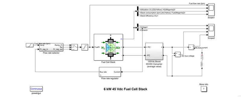
- The vehicle is entirely powered by the fuel cell
- The fuel cell stack is connected through a boost converter to the load as there is a need to match load requirement to the current produced by the fuel cell
- At the input, side is the fuel rate selector by which the fuel flow in l/min can be controlled
- The fuel rate regulator works on the basis of the current input
- Whatever is the current that is delivered by the stack is taken by the regulator as input
- The fuel cell stack is model according to the equivalent circuit shown below:
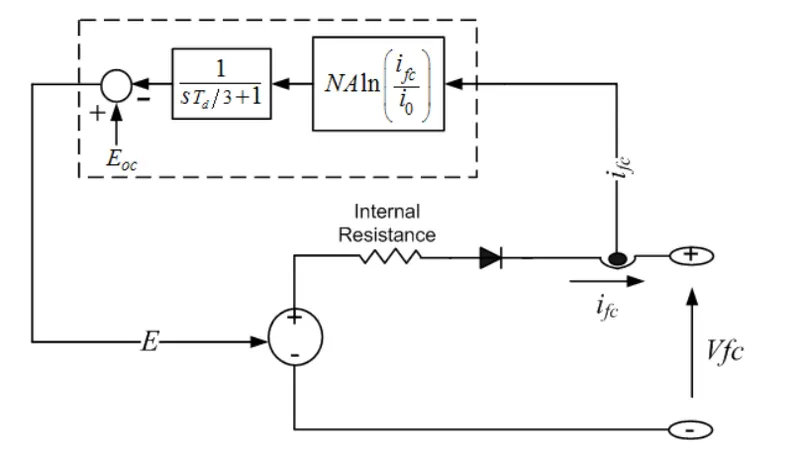
- The diode in the circuit represents that the current in the fuel cell will always be coming out
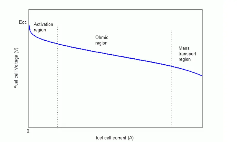
- The V-I characteristics of fuel cell have three different regions of operation, which indicates that the current increases as voltage decreases
-
- Model description:
-
The nominal Fuel Cell Stack voltage is 45Vdc and the nominal power is 6kW. The converter is loaded by an RL element of 6kW with a time constant of 1 sec. During the first 10 secs, the utilization of the hydrogen is constant to the nominal value (Uf_H2 = 99.56%) using a fuel flow rate regulator. After 10 secs, the flow rate regulator is bypassed and the rate of fuel is increased to the maximum value of 85 lpm in order to observe the variation in the stack voltage. That will affect the stack efficiency, fuel consumption and air consumption. Fuel cell voltage, current, DC/DC converter voltage, and DC/DC converter current signals are available on Scope2. Fuel flow rate, Hydrogen and oxygen utilization, fuel and air consumption, and efficiency are available on Scope1.
- 3) Simulation results and inference:
- a) V-I characteristics of fuel cell and Load
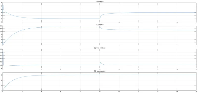
- The voltage falls to 45 when started, during this time there will be an increase. This is because of the inherent of RL load where there is a peak in current at the start. More voltage implies an increase in flow rate ay t=10s which reflects a fall in the current flow from the fuel cell.
- The DC DC converter does not allow any fluctuation in load voltage.
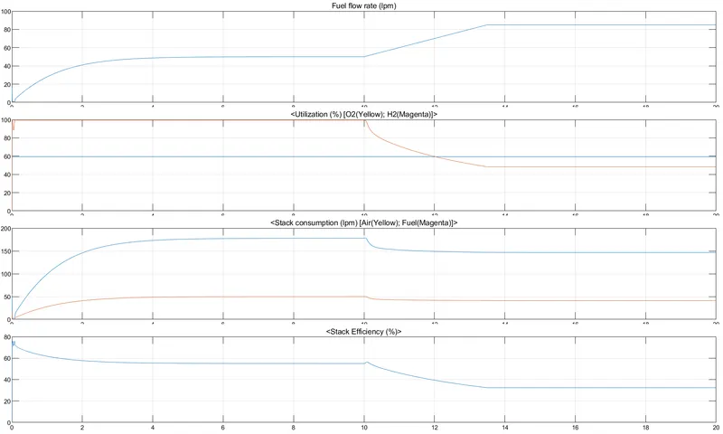
- The fuel flow rate is changed from the t= 10 s
- The flow rate is ramped up from 10 th to 13 s
- From the efficiency plot, it can be inferred that as flow rate increases stack efficiency decreases
- Response to a WOT drive cycle where there is a need of peak power:
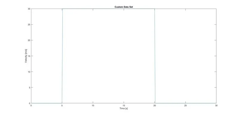
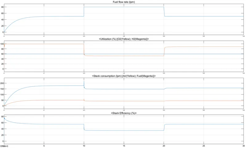
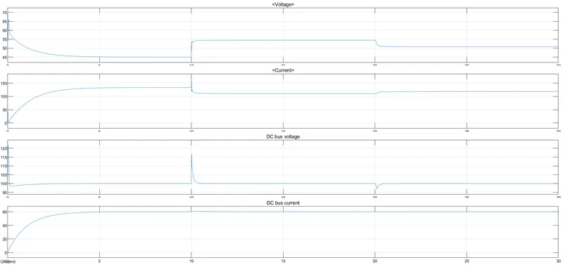
- The peak demand of WOT is between 5 s to 20s where full-throttle is given it can be seen from V-I characteristics of fuel cell that when the peak power is delivered there is an increase in voltage with a fall in the current. The increased flow rate also causes a fall in stack efficiency during the same period.