Simulation of Fuel Cell Powered Vehicle
Fuel Cell
A fuel cell is an electrochemical cell that converts the chemical energy of a fuel (often hydrogen) and an oxidizing agent (often oxygen) into electricity through a pair of redox reactions. Fuel cells are different from most batteries in requiring a continuous source of fuel and oxygen (usually from air) to sustain the chemical reaction, whereas in a battery the chemical energy usually comes from metals and their ions or oxides that are commonly already present in the battery, except in flow batteries. Fuel cells can produce electricity continuously for as long as fuel and oxygen are supplied.
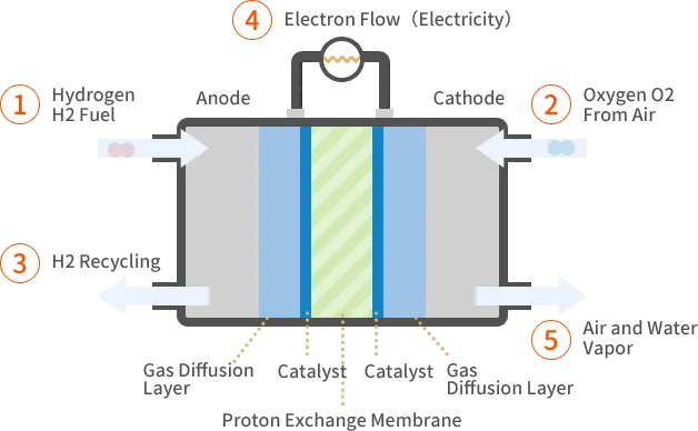
There are many types of fuel cells, but they all consist of an anode, a cathode, and an electrolyte that allows ions, often positively charged hydrogen ions (protons), to move between the two sides of the fuel cell. At the anode a catalyst causes the fuel to undergo oxidation reactions that generate ions (often positively charged hydrogen ions) and electrons. The ions move from the anode to the cathode through the electrolyte. At the same time, electrons flow from the anode to the cathode through an external circuit, producing direct current electricity. At the cathode, another catalyst causes ions, electrons, and oxygen to react, forming water and possibly other products.
Individual fuel cells produce relatively small electrical potentials, about 0.7 volts, so cells are "stacked", or placed in series, to create sufficient voltage to meet an application's requirements.
In addition to electricity, fuel cells produce water, heat, and depending on the fuel source, very small amounts of nitrogen dioxide and other emissions. The energy efficiency of a fuel cell is generally between 40 and 60%. However, if waste heat is captured in a cogeneration scheme, efficiencies of up to 85% can be obtained.
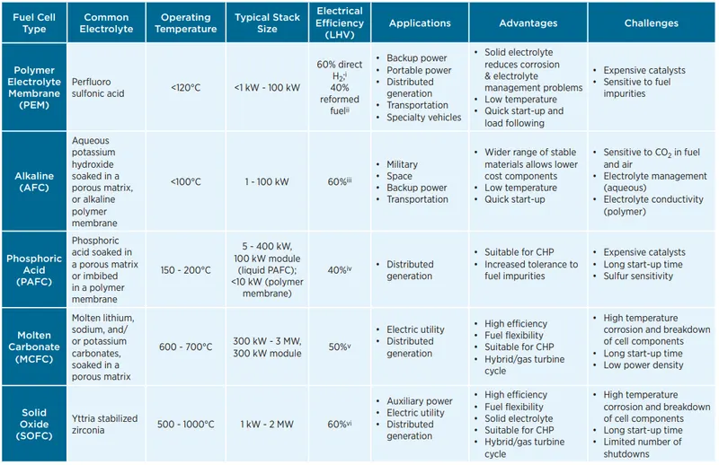
Fuel cells are classified by the type of electrolyte they use and by the difference in startup time ranging from 1 second for proton exchange membrane fuel cells (PEM fuel cells, or PEMFC) to 10 minutes for solid oxide fuel cells (SOFC).
Types of Fuel Cell Design
Fuel cells are made of three adjacent segments, the anode, the electrolyte, and the cathode. Two chemical reactions occur at the interfaces of the three different segments. The net result of the two reactions is that fuel is consumed, water or carbon dioxide is created, and an electric current is created, which can be used to power electrical devices, normally referred to as the load.
Design features in a fuel cell
- The electrolyte substance, which usually defines the type of fuel cell, and can be made from a number of substances like potassium hydroxide, salt carbonates, and phosphoric acid.
- The fuel that is used. The most common fuel is hydrogen.
- The anode catalyst, usually fine platinum powder, breaks down the fuel into electrons and ions.
- The cathode catalyst, often nickel, converts ions into waste chemicals, with water being the most common type of waste.
- Gas diffusion layers that are designed to resist oxidization.
A typical fuel cell produces a voltage from 0.6 to 0.7 V at full rated load. Voltage decreases as current increases, due to several factors such as
- Activation loss
- Ohmic loss (voltage drop due to resistance of the cell components and interconnections)
- Mass transport loss (depletion of reactants at catalyst sites under high loads, causing rapid loss of voltage).
To deliver the desired amount of energy, the fuel cells can be combined in series to yield higher voltage, and in parallel to allow a higher current to be supplied. Such a design is called a fuel cell stack. The cell surface area can also be increased, to allow higher current from each cell.
Proton-exchange membrane fuel cells (PEMFCs)
Proton-exchange membrane fuel cells (PEMFC), also known as polymer electrolyte membrane (PEM) fuel cells, are a type of fuel cell being developed mainly for transport applications, as well as for stationary fuel-cell applications and portable fuel-cell applications. Their distinguishing features include lower temperature/pressure ranges (50 to 100 °C) and a special proton-conducting polymer electrolyte membrane.
Phosphoric acid fuel cell (PAFC)
Phosphoric acid fuel cells (PAFC) are a type of fuel cell that uses liquid phosphoric acid as an electrolyte. They were the first fuel cells to be commercialized. The electrolyte is highly concentrated or pure liquid phosphoric acid (H3PO4) saturated in a silicon carbide matrix (SiC). Operating range is about 150 to 210 °C. This high temperature will cause heat and energy loss if the heat is not removed and used properly. This heat can be used to produce steam for air conditioning systems or any other thermal energy-consuming system. Using this heat in cogeneration can enhance the efficiency of phosphoric acid fuel cells from 40 to 50% to about 80%. The electrodes are made of carbon paper coated with a finely dispersed platinum catalyst.
Solid acid fuel cell (SAFC)
Solid acid fuel cells (SAFCs) are a class of fuel cells characterized by the use of a solid acid material as the electrolyte. Similar to proton exchange membrane fuel cells and solid oxide fuel cells, they extract electricity from the electrochemical conversion of hydrogen- and oxygen-containing gases, leaving only water as a byproduct. Current SAFC systems use hydrogen gas obtained from a range of different fuels, such as industrial-grade propane and diesel. They operate at mid-range temperatures, from 200 to 300 °C.
Alkaline Fuel Cell (AFC)
Alkaline fuel cells consume hydrogen and pure oxygen, to produce potable water, heat, and electricity. They are among the most efficient fuel cells, having the potential to reach 70%. The cell consists of two porous carbon electrodes impregnated with a suitable catalyst such as Pt, Ag, CoO, etc. The space between the two electrodes is filled with a concentrated solution of KOH or NaOH which serves as an electrolyte. H2 gas and O2 gas are bubbled into the electrolyte through the porous carbon electrodes. Thus the overall reaction involves the combination of hydrogen gas and oxygen gas to form water. The cell runs continuously until the reactant's supply is exhausted. This type of cell operates efficiently in the temperature range 343–413 K and provides a potential of about 0.9 V. AAEMFC is a type of AFC which employs a solid polymer electrolyte instead of aqueous potassium hydroxide (KOH) and it is superior to aqueous AFC.
Solid oxide fuel cells (SOFCs)
Solid oxide fuel cells (SOFCs) use a solid material, most commonly a ceramic material called yttria-stabilized zirconia (YSZ), as the electrolyte. Because SOFCs are made entirely of solid materials, they are not limited to the flat plane configuration of other types of fuel cells and are often designed as rolled tubes. They require high operating temperatures (800–1000 °C) and can be run on a variety of fuels including natural gas.
A solid oxide fuel cell (or SOFC) is an electrochemical conversion device that produces electricity directly from oxidizing a fuel. Fuel cells are characterized by their electrolyte material; the SOFC has a solid oxide or ceramic electrolyte.
Advantages of this class of fuel cells include high combined heat and power efficiency, long-term stability, fuel flexibility, low emissions, and relatively low cost. The largest disadvantage is the high operating temperature which results in longer start-up times and mechanical and chemical compatibility issues.
Molten-carbonate fuel cell (MCFC)
Molten carbonate fuel cells (MCFCs) require a high operating temperature, 650 °C (1,200 °F), similar to SOFCs. MCFCs use lithium potassium carbonate salt as an electrolyte, and this salt liquefies at high temperatures, allowing for the movement of charge within the cell – in this case, negative carbonate ions. Like SOFCs, MCFCs are capable of converting fossil fuel to a hydrogen-rich gas in the anode, eliminating the need to produce hydrogen externally. The reforming process creates carbon-dioxide emissions.
Comparison of various Fuel Cell Technologies
Drive Cycle: FTP-72 (UDDS)
The US FTP-72 (Federal Test Procedure) cycle is also called the Urban Dynamometer Driving Schedule (UDDS). The cycle simulates an urban route of 7.5 mi (12.07 km) with frequent stops. The maximum speed is 56.7 mph (91.25 km/h) and the average speed is 19.6 mph (31.5 km/h).
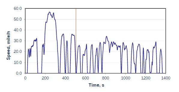
The cycle consists of two phases: (1) 505 s (5.78 km at 41.2 km/h average speed) and (2) 867 s. The first phase begins with a cold start. Weighting factors of 0.43 and 0.57 are applied to the first and second phase, respectively. Emissions are expressed in g/mile or g/km.
Fuel cell-powered Electric Vehicle Model
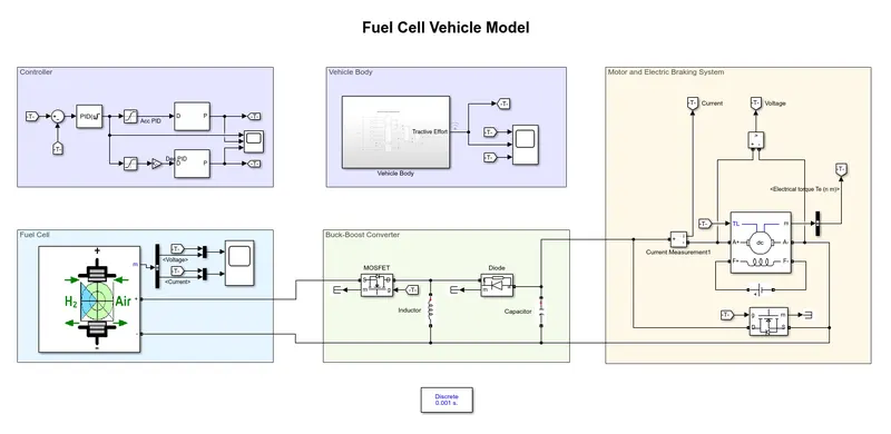
The fuel cell vehicle model consists of five major subsystem
- Controller
- Vehicle Body
- Fuel Cell
- Buck-Boost Converter
- Motor and Electric Braking
Controller
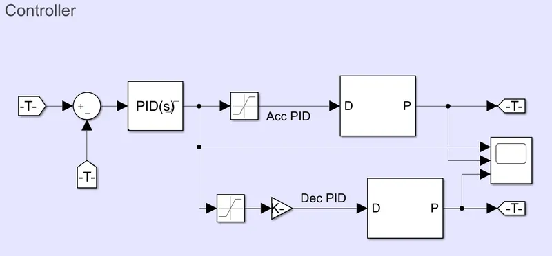
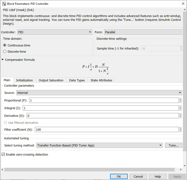
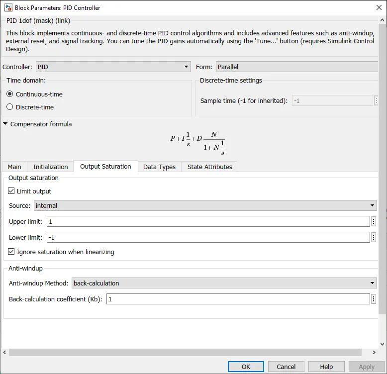
The controller subsystem consists of a PID controller which takes the error signal by comparing the vehicle body torque requirement and the actual torque generated by the motor. The controller output is then separated as acceleration and deceleration signal using the saturation block. The acceleration and deceleration are then used to generate the PWM control signal considering the input as the duty cycle. An anti-windup technique, back-calculation method is used to control the overshoot from the PID Controller.
Vehicle Body
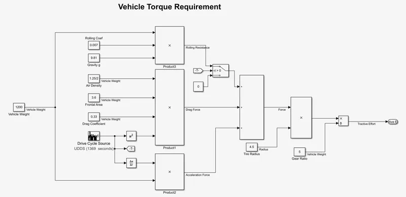
The vehicle body subsystem calculates the vehicle torque requirement based on the assumed weight of the vehicle and the drive cycle speed. All the forces acting on the moving vehicle such as Rolling Resistance, Air Drag and Acceleration forces are calculated and the torque requirement from the motor is calculated by assuming the tire size and the geat ratio.
Fuel Cell
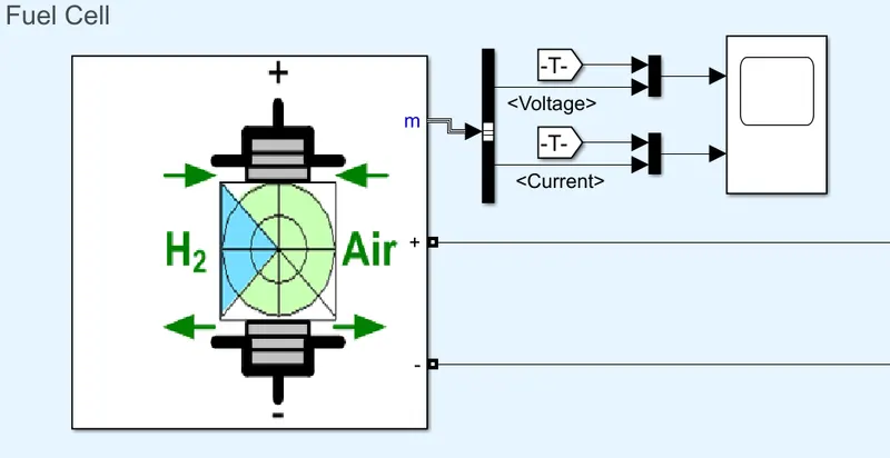
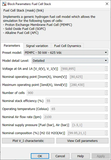
A proton exchange membrane fuel cell stack of power 50kW is used to power the electric motor. The Signal variation and Fuel Cell Dynamics parameters are kept in default values.
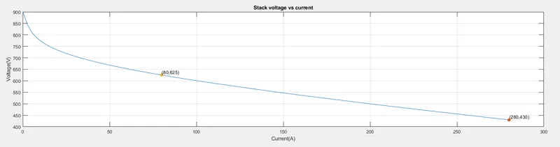
Voltage vs Current characteristics of the Fuel Cell
The voltage vs current characteristics shows that the voltage and current developed by the fuel cell are inversely proportional to each other.
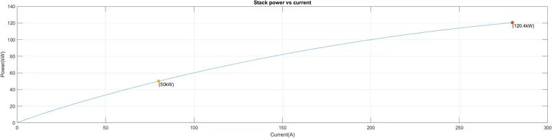
The power developed by the fuel cell increases with the increase in current.
Buck-Boost Converter
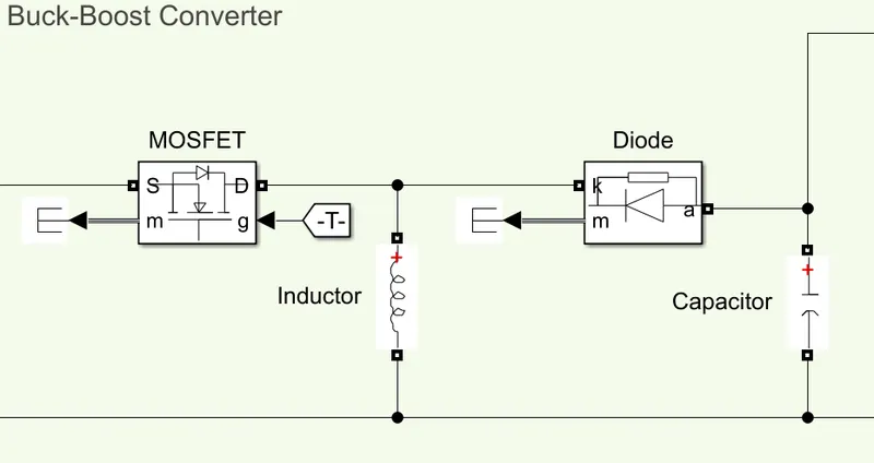
The buck-boost converter can work as both step-up and step-down converter, hence we use a buck-boost converter to maintain the voltage across the motor.
Motor and Electric Braking
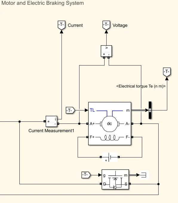
The motor can produce the required torque for acceleration from the input power but incase of deceleration we need to either use mechanical braking or electrical braking to achieve the required braking torque requirement from the vehicle. This braking torque requirement is used to achieved using the dynamic braking technique where instead of utilising the regenerative braking the armature is short-circuited and the required braking torque is achieved.
Results
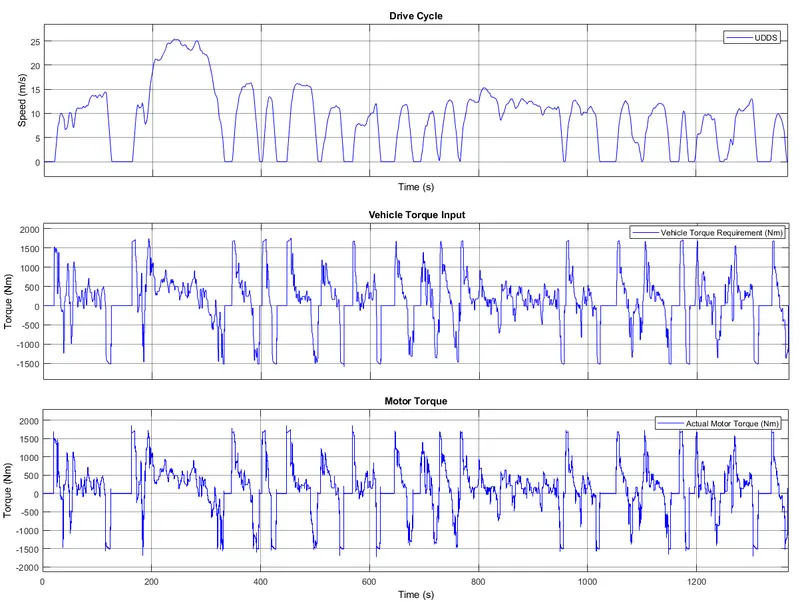
The fuel cell-powered electric vehicle model is simulated using the UDDS drive cycle from which we calculate the vehicle torque requirements and use as a reference in controlling the vehicle. The vehicle torque requirement is fulfilled with a minimal error which can be further improved by reducing the response time for the fuel cell stack.
Response Time of Fuel Cell
In-vehicle applications fuel cells operate under load change conditions. Sudden load changes may result in improper water management and reactant starvation phenomena due to the slow response of the cell to load change, which results in performance loss and short lifetime. So understanding the dynamic behaviour of fuel cell is essential to achieve longer fuel cell lifetime and better performance.
References
1. https://en.wikipedia.org/wiki/Fuel_cell
2. https://www.energy.gov/sites/prod/files/2015/11/f27/fcto_fuel_cells_fact_sheet.pdf