Week 6 Fuel cell powered vehicle model
AIM:
Make a MATLAB model of fuel cell powered electric vehicle and comment on results
THEORY:
What is a fuel cell electric vehicle?
Fuel cell is an electrochemical device that generates electricity from energy stored as hydrogen. Unlike conventional internal combustion engine vehicles, they have high energy efficiency and lower tail pipe emissions. Fuel cell alone is not capable of high power so in vehicles they are combined with a small battery or supercapacitor, to power its on-board electric motor. There are different types of fuel cells in which PEM (Polymer electrolyte membrane) is commonly used for vehicle application.
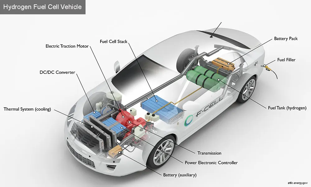
FIG: Hydrogen fuel cell vehicle
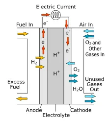
FIG: Fuel cell
In a PEM fuel cell, an electrolyte membrane is sandwiched between a positive electrode (cathode) and a negative electrode (anode). Hydrogen is supplied to anode where hydrogen molecules break into protons and electrons. In anode oxygen is introduced where hydrogen and oxygen are combined to produce electricity and water.
Overall cell reaction: `H_2+1/2 O_2→H_2 O`
SIMULINK MODEL:
Working:
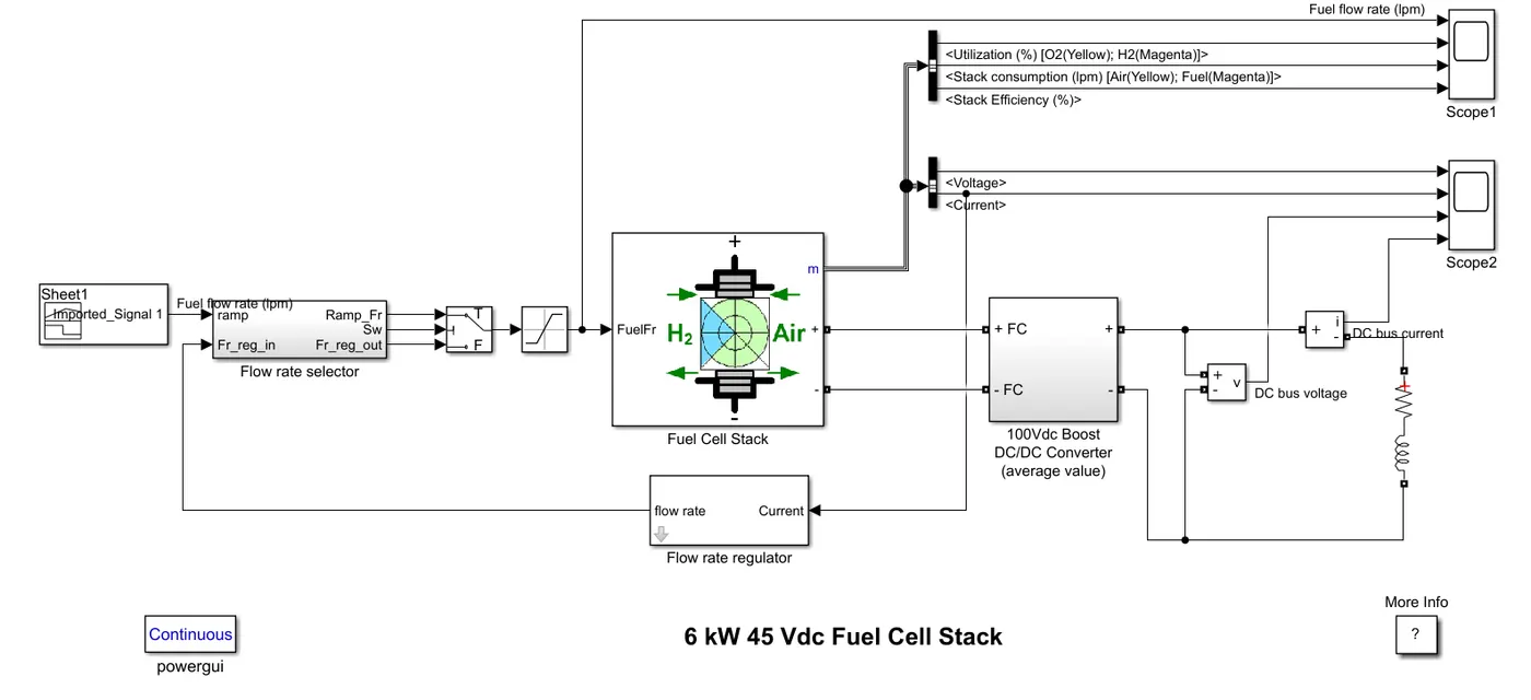
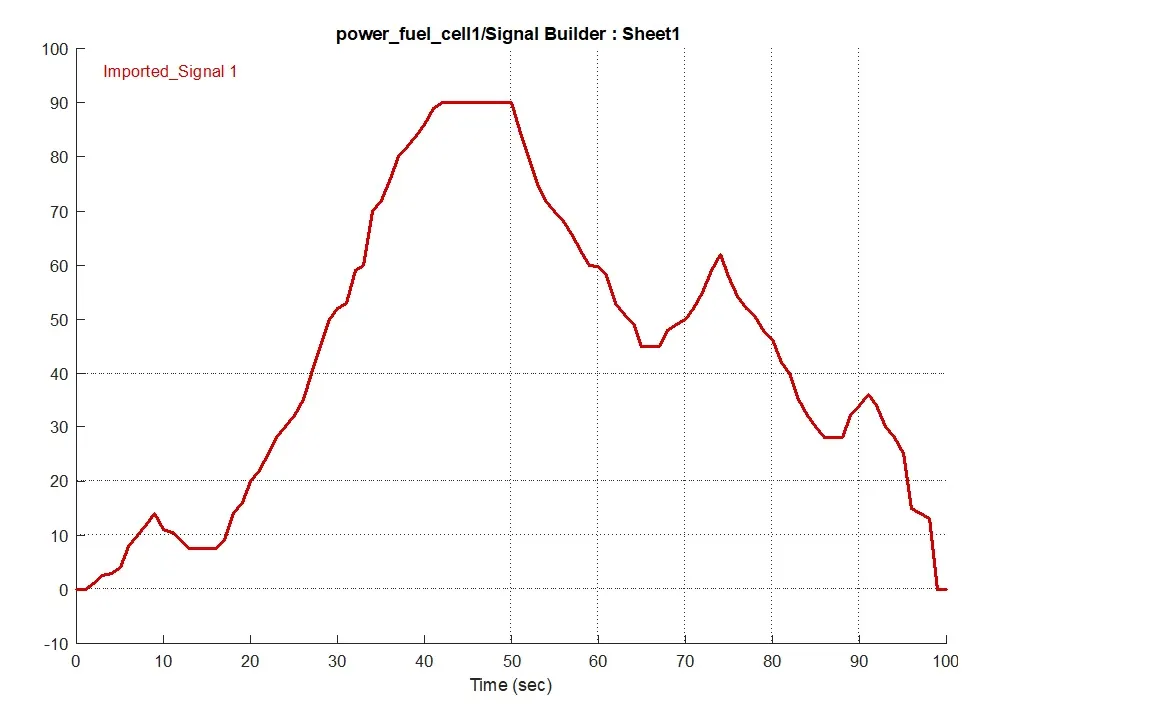
This model is a fuel stack with 45Vdc nominal voltage and a nominal power of 6kW. The converter is loaded by an RL element of 6kW with a time constant of 1sec. For the first 10sec, the utilization of the hydrogen is 99.56%. After 10sec the rate of flow is varied between 0 and 90 lpm in order to observe the variation in stack voltage. That will affect the stack efficiency, the fuel consumption and the air consumption.
Blocks used:
Signal Builder: It is used to produce flow rate. Instead of signal builder we can use ramp block also to give the flow rate.
Fuel rate selector:
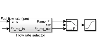
This 3 block combined performance gives the fuel flow rate. Fuel selector block helps to get the switching signals. Fuel selector takes input from fuel flow rate and flow rate from regulator. The flow rate selector selects the flow rate from regulator for first 10sec and for the rest of time it selects the fuel flow rate using the switch block. The saturation block limits the flow rate to 90 lpm.
Flow rate regulator:
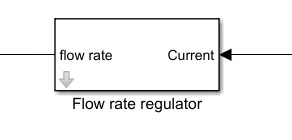
This block take input from current and give output as flow rate. It need parameters like number of cells, nominal hydrogen utilization, operation temperature, fuel pressure, H2 composition. With these parameters it calculate the flow rate. It is regulated according to the current.
Fuel cell stack:
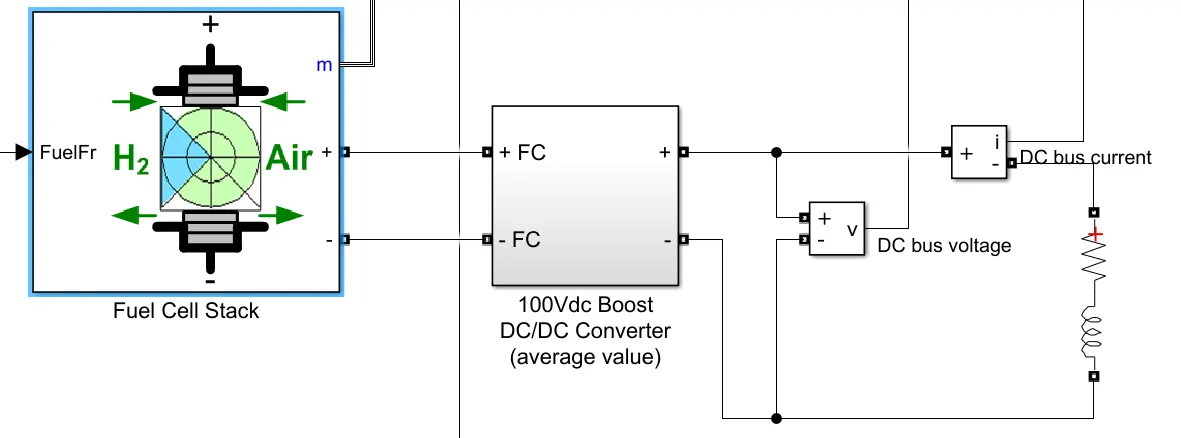
The Fuel Cell Stack block (highlighted block) implements a generic model parameterized to represent most popular types of fuel cell stacks fed with hydrogen and air. Here we are using PEMFC 6kW 45Vdc fuel cell. Fuel cell model feeding an average value of 100Vdc dc/dc converter and RL load. Voltmeter and ammeter are also attached to measure the current and voltage to the RL load. From the m terminal we are scoping fuel voltage, current on Scope2. Fuel flow rate, Hydrogen and oxygen utilization, fuel and air consumption, and efficiency on Scope1.
Steps involved in configuring the model:
- The load reference was set according to a drive cycle using signal builder.
- The upper limit of saturation block set as 90lpm.
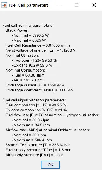
- Model the fuel stack with 6kW 45Vdc type model. The cell specification is given below.
Cell specification:
RESULTS:
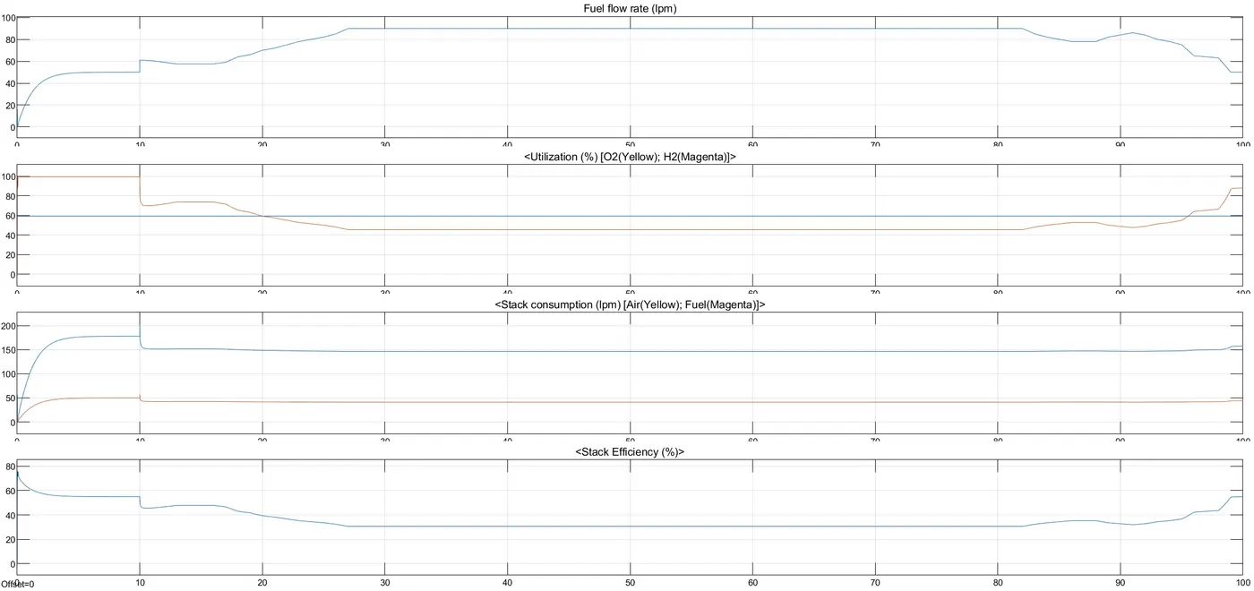
FIG: Scope 1 results
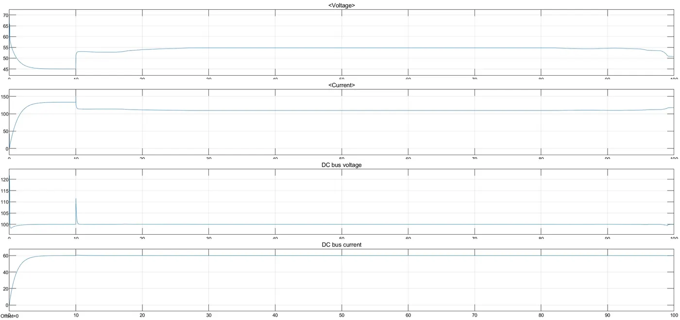
FIG: Scope 2 results
The result shows how oxygen and hydrogen are utilized and consumed. And how the utilization of fuel affect the efficiency. During the first 10sec, the utilization of hydrogen is constant to the nominal value 99.56%. At 10sec the flow rate increased from 50lpm to 90lpm during this period hydrogen utilization decreased. This causes increase in voltage so the fuel cell current will decrease. Therefore stack consumption and efficiency will decrease. And after 80sec the flow rate decrease and you can see that again the stack efficiency is getting higher. When you look the DC bus voltage graph at 10sec you can see a peak voltage that is due to the transient condition during switching. Also from same graph you can see that at initial time the bus voltage was around 120V and it was effectively controlled by DC/DC converter and bring down the voltage to 100V within milliseconds.