Week 6 - Creating connection for Rear door
AIM:
To create and deploy connections for the given model of a rear car dood.
PROCEDURE:
1.First import the given cad model to the ANSA .As the given model is meshed and the required processes are finished we can straightly proceed to deploy connections.
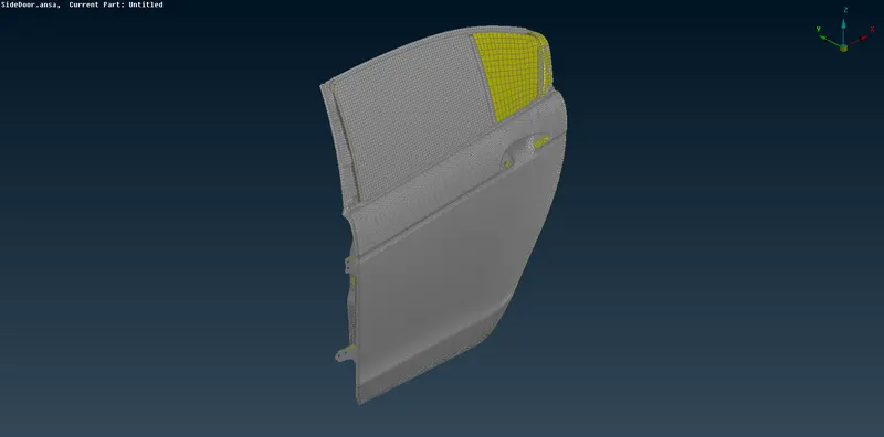
2.CONNECTING HINGES:
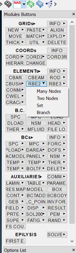
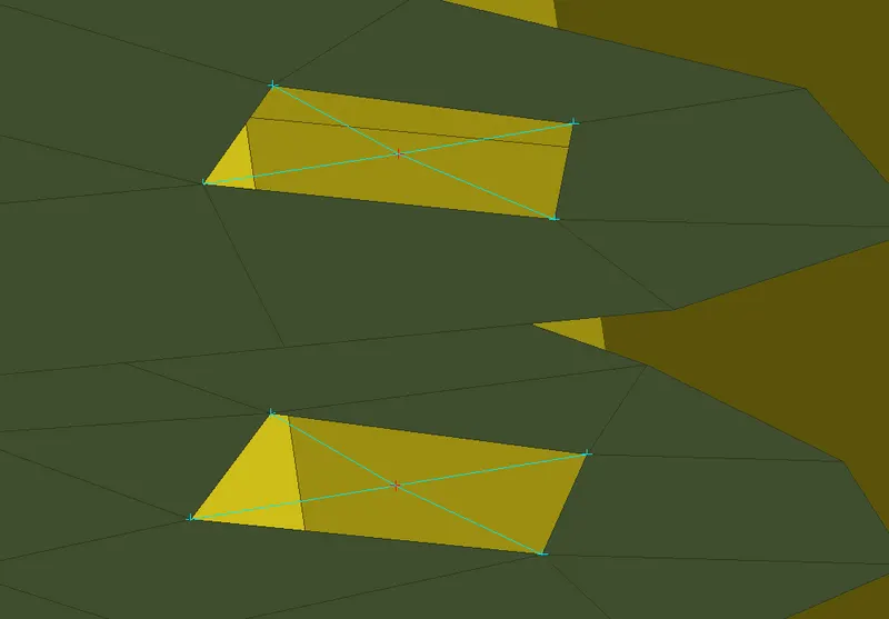
To connect the hinges we here use RBE2 elements.First create seperate PID for hinges, then the holes where rigid connections have to be deployed using NASTRAN deck>>Elements>>RBE2>>Many nodes command.
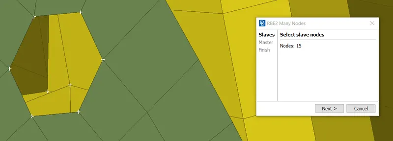
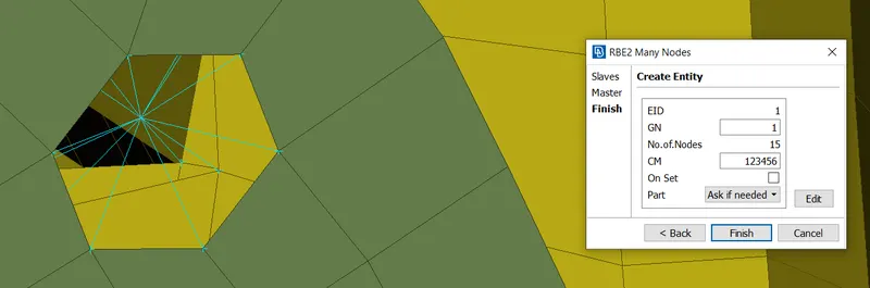
RBE2 CLUSTER FORMED AND RIGID CONNECTION ESTABLISHED
Similarly create RBE2 elements for these holes and connect those using RBE2 elements with two node option .After selecting the master nodes a dialog box appears in which CM (denotion of degree of freedom ) should be set to 12345 to restrict the motion of the hinge in z axis.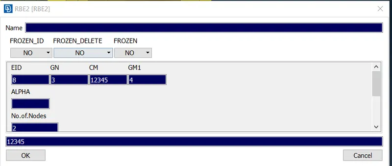
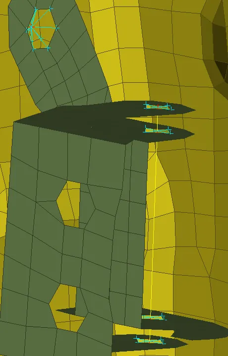
CONNECTION ESTABLISHED
3. Now create similar RBE2 elements in all necessary areas for the model.
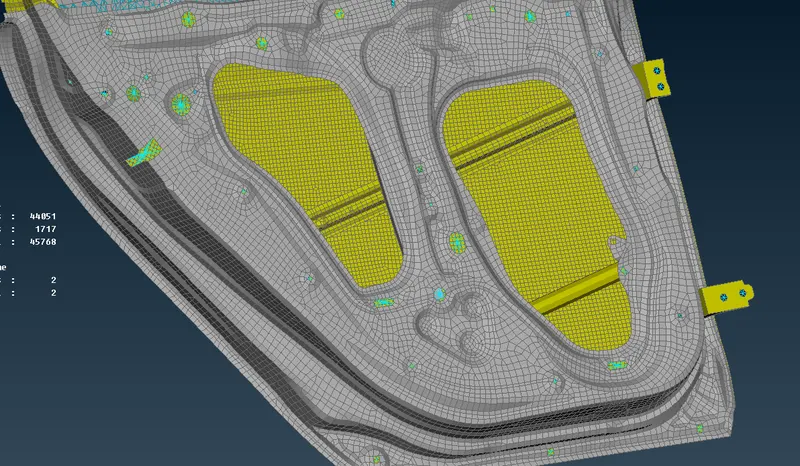
4.CONNECTIONS BETWEEN DOOR HANDLE:
For deploying connections at the door handle regions we can use RBE2 elements itslef.Now we have to connect the master nodes of the door handle holes and form a new RBE element to represent the weight of the door handle.
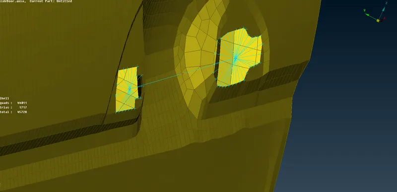
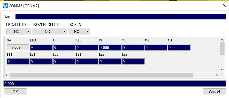
Now to apply the weight go to CONMi>>CONM2>>Nodes and select the master node between the provisions and input the given mass value in tonnes.(Give M=0.0001)
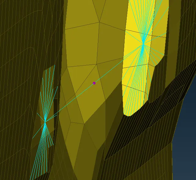
AFTER APPLYING WEIGHT
5.CREATING CONNECTION BETWEEN GLASS AND RAILS
To establish a connection between the glass and rail first isolate both those components to get a clear view.
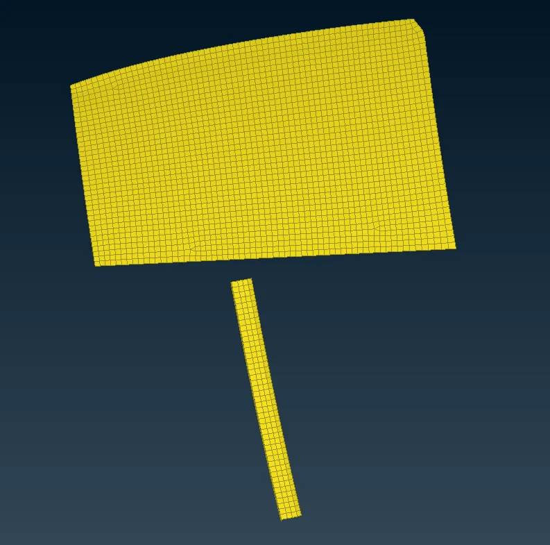
After isolating we have to extend the rail till glass level to establish connection to do that go to Mesh module>>Grids>>MVFree and select the top nodes and extend till the glass level.
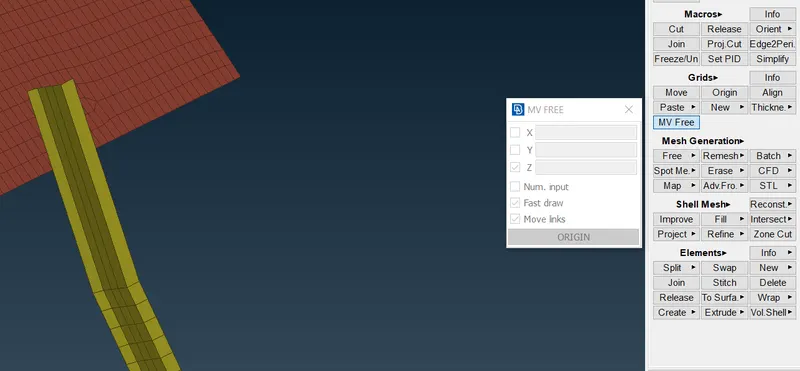
Now reconstruct the mesh using 9 as target element length at the extended portion.Now we have to establish connection using RBE2 cluster element connection.
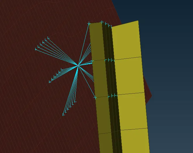
6.DEPLOYING CONNECTIONS FOR SPOT WELD POINTS
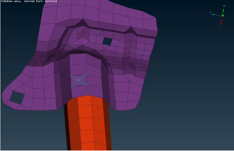
In order to create a spot weld representation we need a COG point where the weld is to be done.To create COG point go to Topo Module>>Points>>On COG>>Edges. Now convert the 3d point as Spotweld point in convert option.
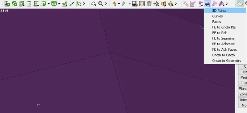
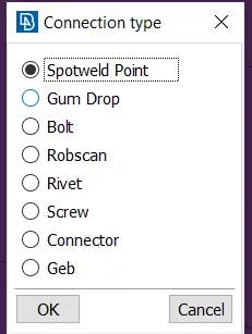
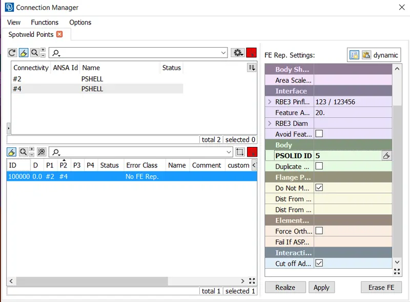
Now open the connection manger and select the spotweld point.In FE representation select RBE3-HEXA-RBE3 and select the P1 and P2 properly .Set the search distance and click apply and realize.Now the spotweld connection is established.
7.CREATING CBUSH CONNECTION
To create a CBUSH connection first create curves on the perimeter using Mesh module>>Perimeters>>Feat2Curve option and select the perimeter and click ok .Now the curves will be created.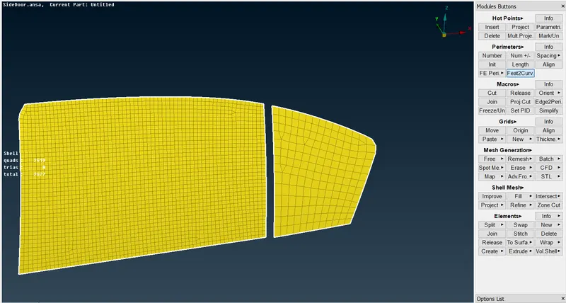
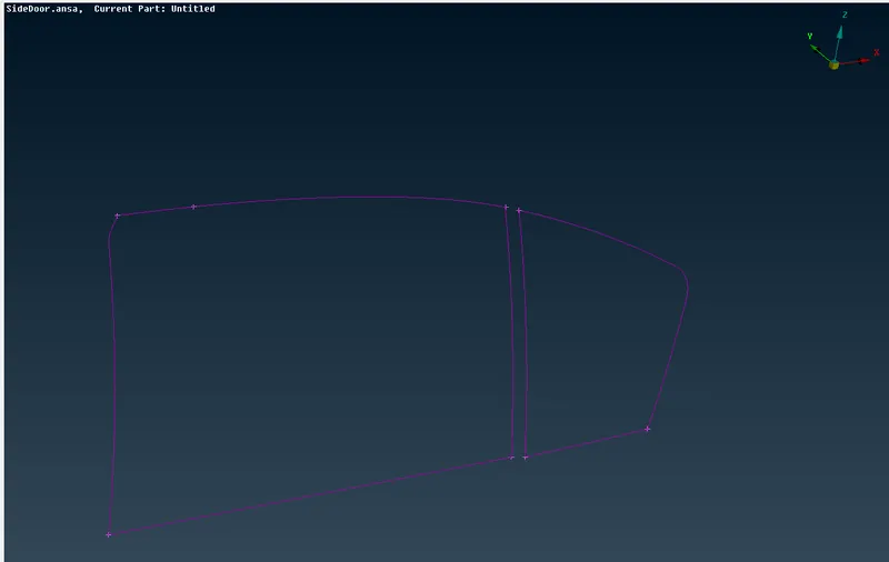
Here the weather strips are on both sides of the glass at bottom so the CBUSH elements should be deployed on both sides.So the bottom curve alone should be copied using transform option at a distance of 10 mm.
Then convert the curves into spot line to deploy connection.To do that go to Utilities>>Convert>>Spot line.
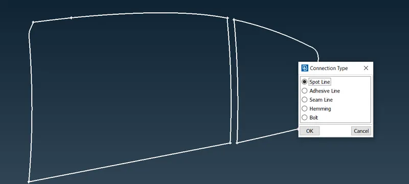
After the curves are converted into spot lines open connection manager and select a curve.
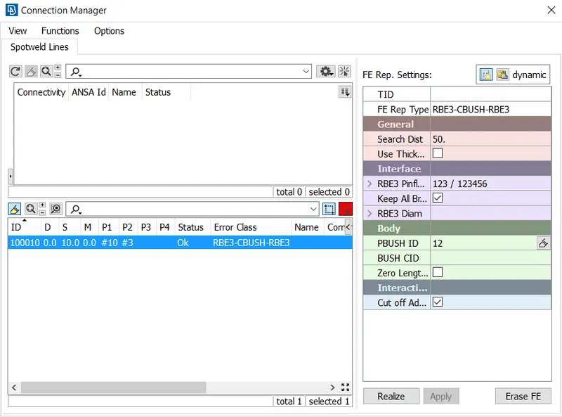
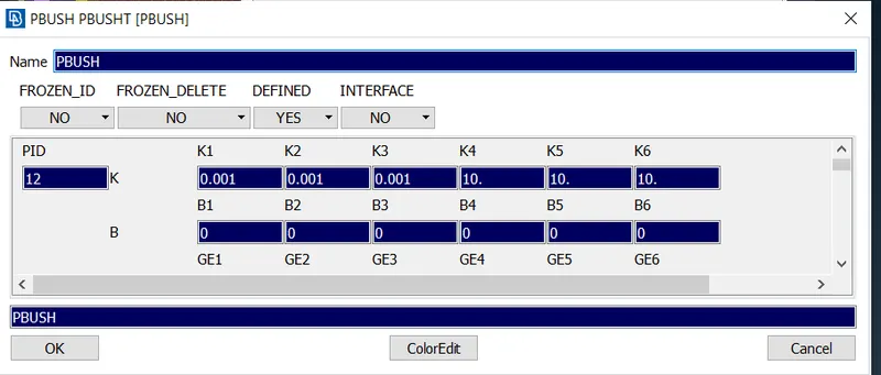
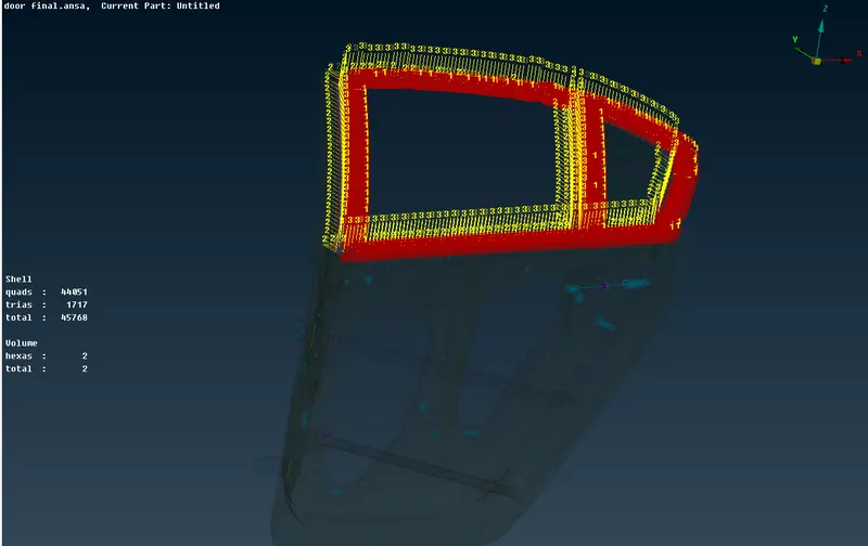
Create a new PBUSH id and enter the stiffness values.Now the CBUSH elements are created on all sides of the glass and we can notice that the CBUSH elements are all in different orientations.So to correct that go to CID elements and select all and right click >> modify.
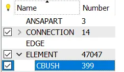
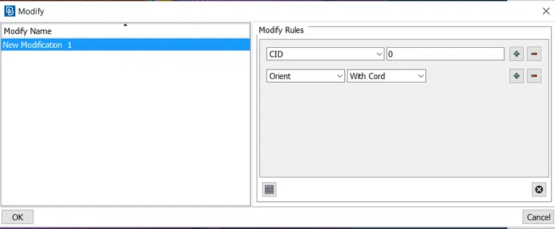
Now all CBUSH elements have been successfully applied.
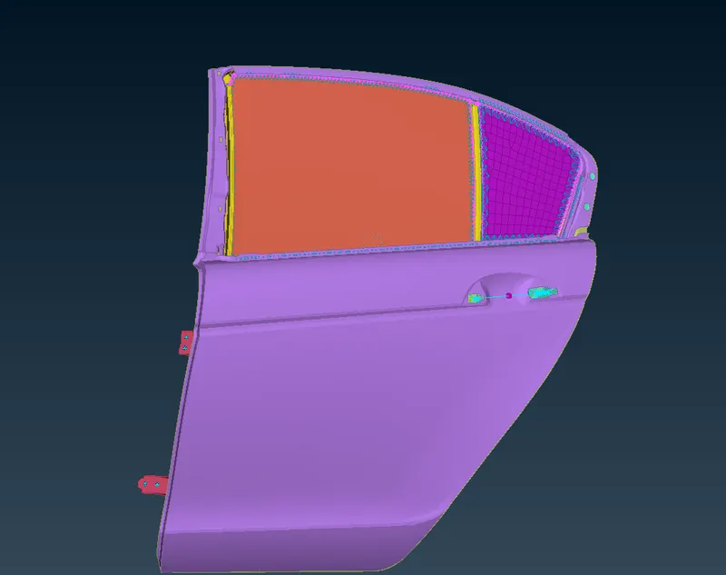
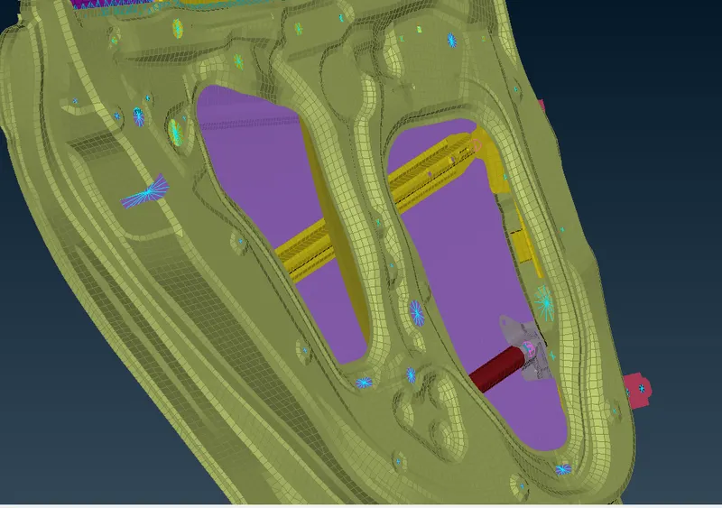
FINAL IMAGES:
RESULT:
Thus the connections for a rear door model has been successfully applied using various element representations.
LEARNING OUTCOMES:
1.Learnt how to deploy connections succesfully using different element types.
2.Performed with connection manger and convert utilities conveniently.