Week 3 - 2D meshing for sheet metal
AIM:
To check geometrical errors and take mid surface for the given hood model and perform meshing on the mid surface with the given quality criteria.
GIVEN QUALITY CRITERIA:
|
S.No |
Quality Criteria |
Value |
|
1 |
Target/Average length |
5 |
|
2 |
Minimum Length |
2 |
|
3 |
Maximum Length |
7 |
|
4 |
Aspect |
3 |
|
5 |
Warpage |
15 |
|
6 |
Skewness |
45 |
|
7 |
Jacobian |
0.7 |
|
8 |
Minimum Quad Angle |
45 |
|
9 |
Maximum Quad Angle |
135 |
|
10 |
Minimum Tria Angle |
30 |
|
11 |
Maximum Tria Angle |
120 |
|
10 |
Tria Percentage |
15 |
PROCEDURE:
1. Iniatially the model has to be imported to the software. This is done by using the following commands File>>Open>>Hood model.stp. The imported model is shown below: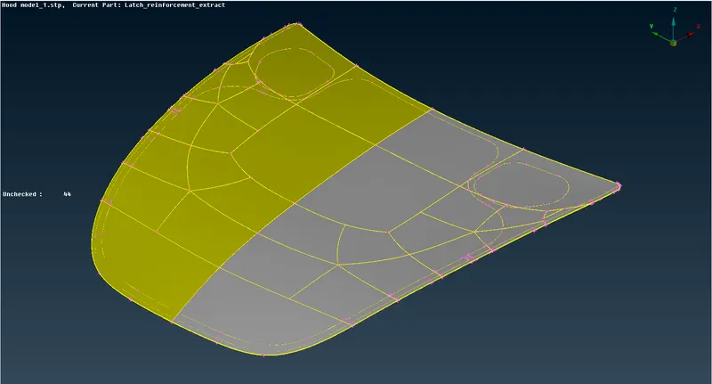
2. We can see that the model has four parts. It has five properties as there are two hinges(left and right).
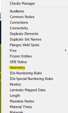
3. Now the model has to be checked for geometrical irregularities.So we open the checks geometry for analysing and correcting the geometrical errors.
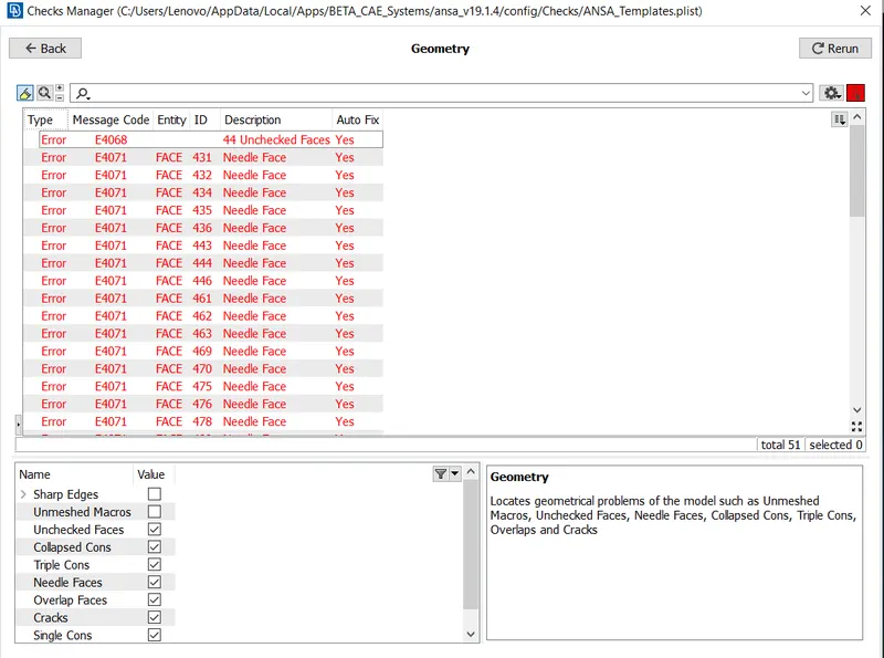
4.Now ANSA checks for geometrical errors and provides the results. If we click FIX , ANSA automatically corrects the errors but not all errors are rectified and corrected by ANSA, some need manual correction. In this model ANSA corrects all the errors so no manual work is needed.
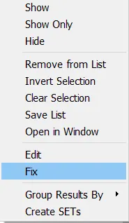
5.Now the all checks are completed and the geometry is fine for further processing.The next part of the process is mid surface extraction.
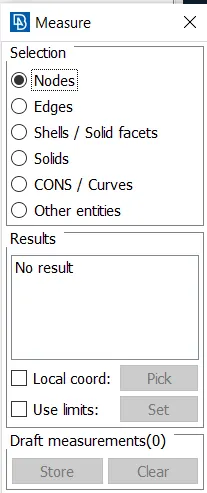
6. Initially we have to measure all the parts thickness individually for mid surface extraction. This is done by Utilities>>Measure command.
7. Now the mid surface can be extracted automatically and manually. Skin Midsurface option is used for automatic extraction and Faces>>offset command is used for manual extraction.Since this is a sheetmetal component automid surface extraction can be opted.
8. Now go to Topo module>>Faces>>Mid surface>> Skin>> Then select the surface . Then give the offset value. 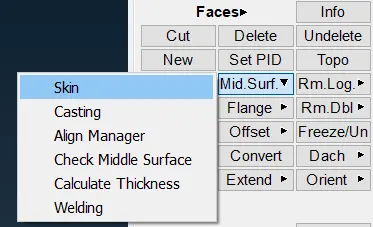
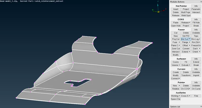
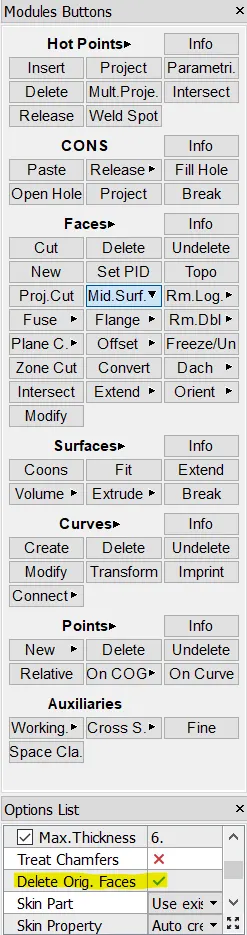
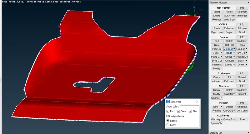
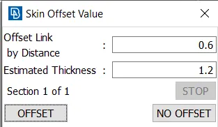
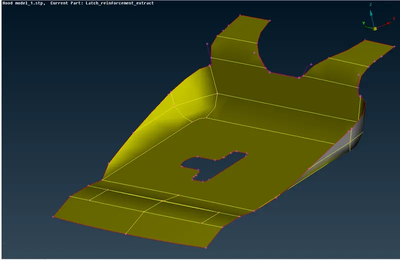
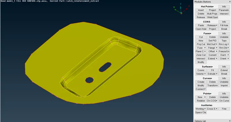
9.Now the mid surface for latch is extracted.While perfoming this command dont forget to uncheck delete original faces in options list because after the mid surface is extracted the parent surface is deleted which we do not need. Now the midsurfaces for all the parts are extracted using the same method.
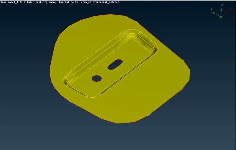
LEFT HINGE MID SURFACE
RIGHT HINGE MID SURFACE
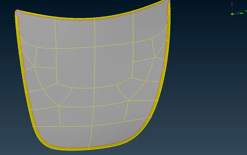
INNER EXTRACT MIDSURFACE
OUTER EXTRACT MID SURFACE
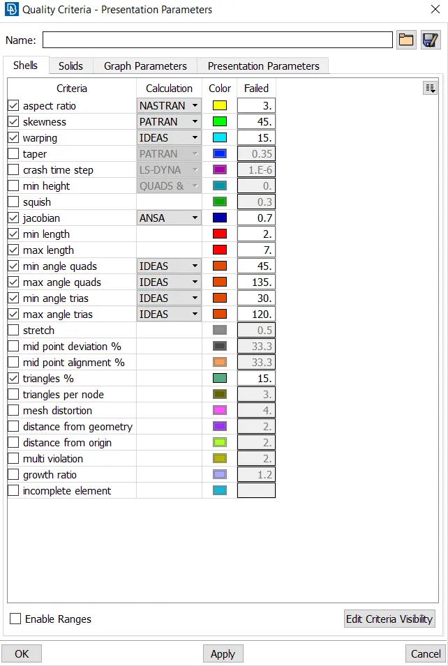
10. Now the model is ready for meshing.First we have to set the quality parameters for meshing. Pres F11 to open the quality criteria dialog box and enter the values as mentioned above.
11. Now enter the mesh parameters . Utilities >> Mesh parameters.
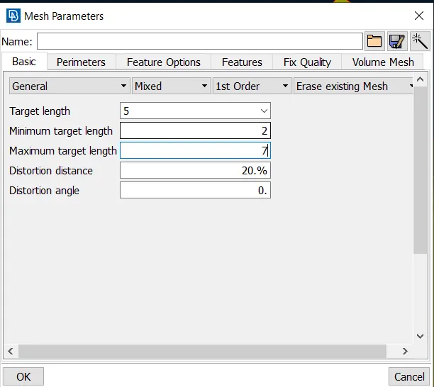
12. Now the perimeter length is set for proper and good mesh flow. Mesh module>>Perimeters>>Length. Set the length as 5 (target element size) and do this for macros also.
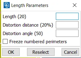
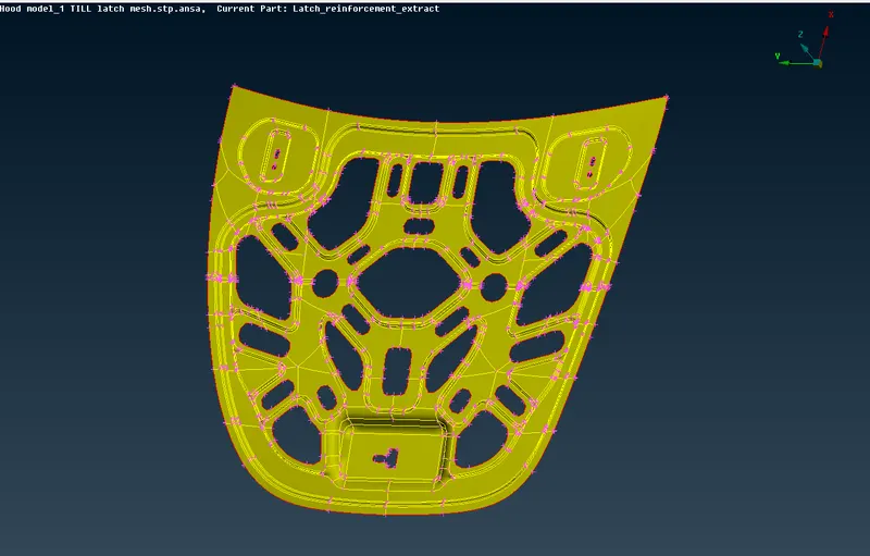
13. Now the meshing has to be done for every parts seperately. Now go to Mesh module>>Mesh generation>>Best mesh and select the area to be meshed. Here best mesh is prefered because this chooses and generates the best possible mesh for component using algorithm.
14. If any error occurs use options like reconstruct , smooth to provide alternative mesh flow which suits according to the criteria.Try to reduce the number of tria elements as much as possible and avoid any trias originating from the edge of the perimeters or geometry.
15.Split command is used for removing trias and swap is used wherever adjacent tria elements are formed.
16.For complex surfaces , suppress the unnecessary cons in topo module which causes element failure thus not meeting quality criteria.
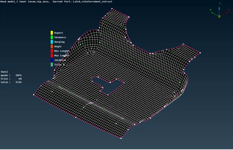
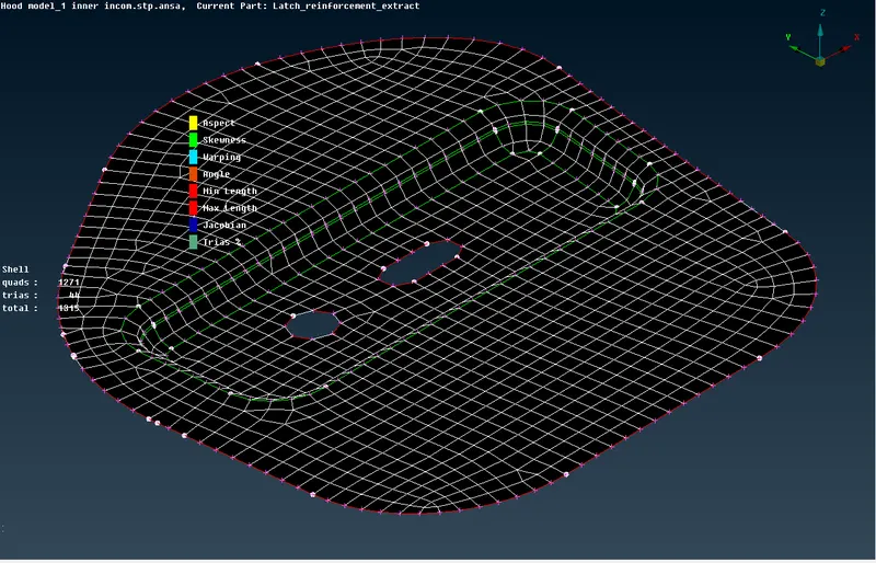
LATCH MESH
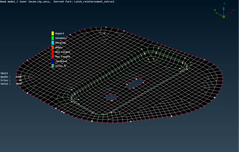
LEFT AND RIGHT HINGES
17.For the outer extract, the hemming region will fail for minimum length criteria so the unnecessary cons are suppressed.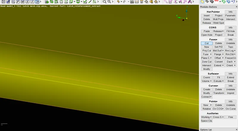
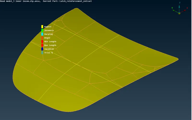
18. The outer extract top surface has many unnecessary cons which may cause disturbance in mesh flow so they can also be toggled and the surface can be split into size as per our need. Here the surface is split into six l halves for good mesh flow.
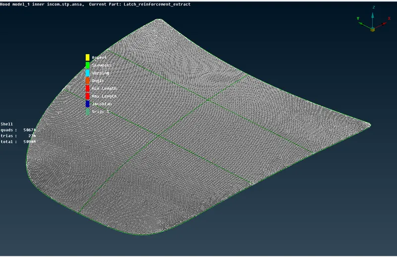
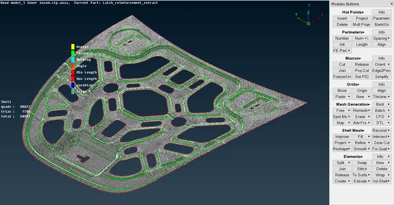
20.For inner component also toggle the unnecessary cons and start meshing as mentioned above.Here both outer and inner extracts are symmetrical we can perform mesh on one side and copy it on the another side and a topo is performed to paste the surfaces.
INNER EXTRACT MESH
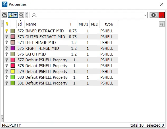
21. Next we have to assign thickness to the components. Since we used auto mid extraction the thickness will be automatically assigned. For manual mid extraction we have to assign thickness manually in properties manager.
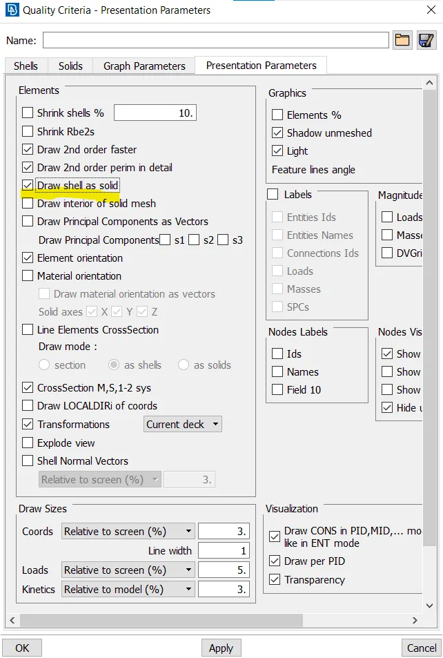
22. To check the assigned thickness , go to presentation parameters and click the Draw shell as solid checkbox. After applying this we can see that the thickness is assigned to the components.
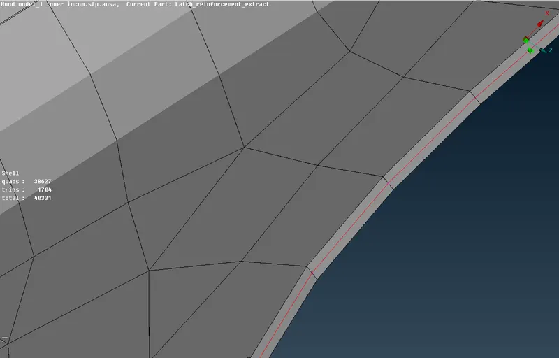
AFTER APPLYING THICKNESS
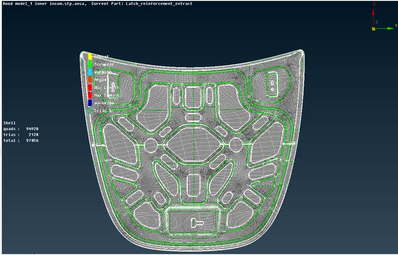
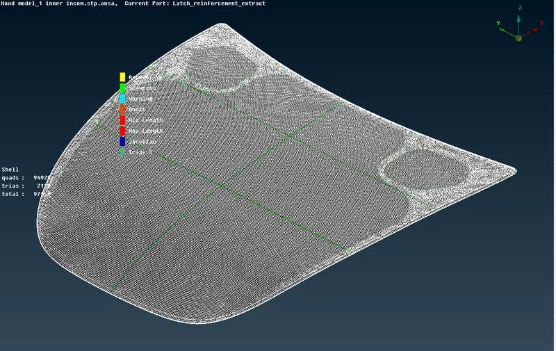
23.Now the process is complete and the final images are attached below:
RESULT:
Thus the given model is checked for geometrical errors , mid surface is extracted and meshed without any element failure as per our quality criteria .
LEARNING OUTCOMES:
1.In this challenge I got a clear idea of working with ANSA and all its primary operations.
2.Learnt different ways for improving mesh quality.
3.Learnt how to assign thickness and fix the mesh as per our quality criteria.