Week 6 - Creating connection for Rear door
AIM: To create and apply different PIDs for different components in a rear door FE model and establish suitable connections between them.
PROCEDURE FOLLOWED:
- Study the FE model
- Create different PIDs for different components.
- Establishing suitable connections
Once the FE model is imported into the ANSA module the model is thoroughly studied for better understanding of where to establish connections.
Create different PIDs:
Different PIDs are assigned to different components using the PSHELL card. The colour differentiation shows different components with different PIDs assigned to the model.
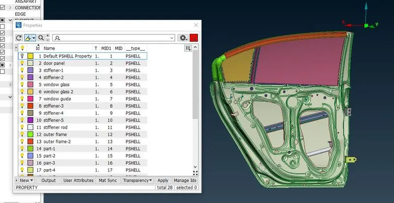
Different PIDs assigned with colour differentiation
once the PIDs are assigned suitable connections between them are assigned.
Establish suitable connections:
Creating connections is the most important part of the pre-processing. There are different types of connections available in ANSA. But each of this connection is used only at a particular interface. In this module weld and Bolt connections are given where ever required.
- Bolt Connection
This is a type of connection where two parts are connected by a bolt and nut. In this type of connection RBE2 (Rigid Body Element) element is used as it rigidly connects the nodes by adding infinite stiffness to it.
In RBE2 there are two types of connections:
- RBE2 (Many nodes): Defines a Rigid body element of form 2 between selected grid points with independent Degree of Freedom DOF specified at a single grid point.
- RBE2 (Two node) : Defines a Rigid body element of form 2 between two selected grid points with independent Degree of Freedom DOF specified at a single grid point.
In this module we have used both types of connections where ever required.
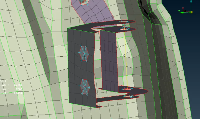
Connection established using RBE2
In the above picture a bracket can be seen which connects the car body to the door with a hinge mechanism in it. The blue lines indicate that the hole of the bracket is fixed with RBE2 (many node) connections and is restricted in all DOF. Hence the bracket cannot move.
There is also a yellow line visible which is represented as hinge with one DOF (rotation about z-axis). This is because the car door is free to rotate about z-axis.
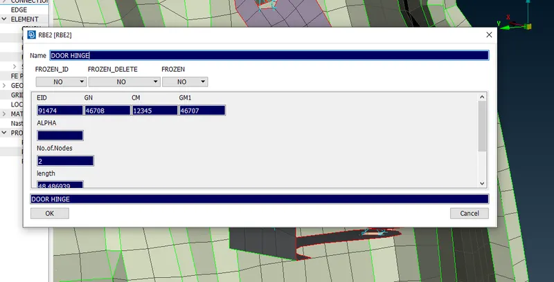
INFO tab of RBE2 showing DOF, EID, etc.
The CM option in the INFO tab of the RBE2 defines the DOF. For eg, if the CM option is assigned with 123456, which means all three translations and three rotations are restricted, where as in the above picture it is assigned with only 12345 which means it is free to rotate about z-axis.
A new part ID is created with CONNECTIONS for assigning all the RBE2 connections.
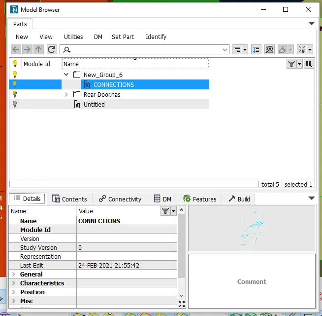
A new Part ID "CONNECTIONS" created
Similar connection is given where ever bolt and nut connection is provided. All these connections are assigned to the newly created CONNECTIONS part.
- Weld Connection
There are two types of welds, 1. Seam weld (welding along a line) 2. Spot weld (welding at a point).
Seam welding is considered in this module. Seam welding connection is assigned using the Shell elements. In this there are two types of shell elements that are used
- Overlap Shell: Used where the surfaces welded are parallel
- Y-Joint Shell: Used where the surfaces welded are perpendicular or angular.
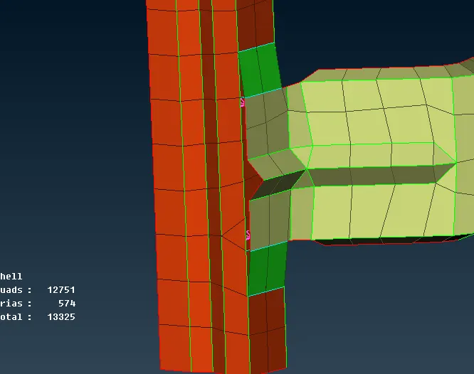
Green coloured shell elements defining weld connection
In the above picture the green shell elements define that the two surfaces are connected by shell weld. The FE representation procedure is as follows:
- Create a curve at the interface
- Convert the curve to connection line (Seam Line)
- Assign connection using the Overlap Shell.
The below picture shows different input parameters assigned for the defining the seam weld using overlap shell
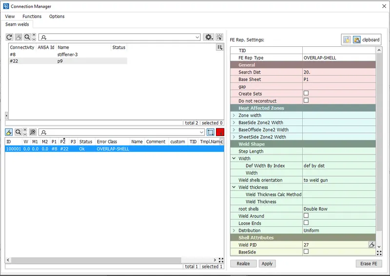
Input parameters for weld connection using overlap shell
Two different parts to be represented as weld connection are assigned. A search distance of 20mm is provided along with the base sheet is assigned. The type of weld with double row is preferred and a new Weld PID is created for assigning the Shell elements.
The same procedure is followed where ever the parallel weld is present. If there are any perpendicular surfaces present these surfaces are connected using Y Joint Shell elements.
A door Handle is also represented as a mass addition by using COMMi element which is used to assign the mass. A RBE2 connection is defined at the holes provided for assembling the door handle. These RBE2 elements are again connected with one more RBE2 element. The centre of this Final RBE2 element is assigned a mass in tonnes.
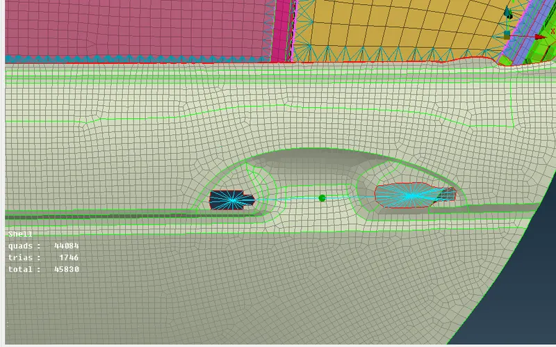
Door handle representation by defining mass
Glass window connection
This is the most critical part of all connections given. As the window to be connected is not rigidly connected other components RBE2 and shell elements cannot be used. They need a special type of elements called CBUSH elements. These elements define a generalized spring-and-damper structural element. Hence these elements does not establish a rigid connection among the two connecting parts.
In this connection CBUSH RBE3 elements are used as they have damping coefficient in all the three directions without adding any stiffness. The procedure followed to create CBUSH connection is as follows:
- Create a curve along the interface of the two components
- convert the curve into a connection line (spot line)
- Create a connection using RBE3 CBUSH element.
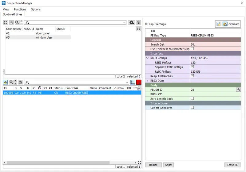
Input parameters for assigning CBUSH elements
Required parameters such as parts to be connected, FE Rep Type, Search Distance, etc. are assigned. A new PID with PBUSH card is created. All the CBUSH connections created are assigned to this PID.
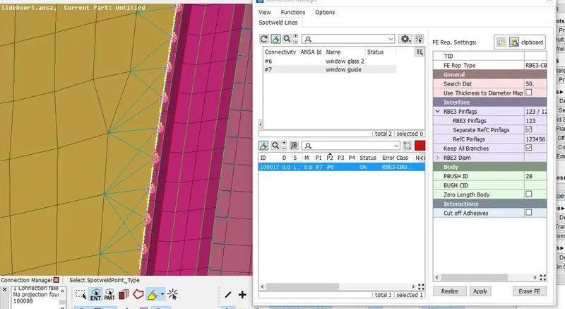
CBUSH elements created
The CBUSH connections created are oriented along the vector. This might result in slight error during the solving of the FE model. Hence present guidelines suggest that it is better to orient the CBUSH elements to the global co-ordinate system. This makes all the CBUSH elements oriented in a single direction irrespective of their connection direction. Hence this is changed by modifying the default orientation set as vector to "0" Co-ordinate system. 0 defined that it is assigned to global co-ordinate system.
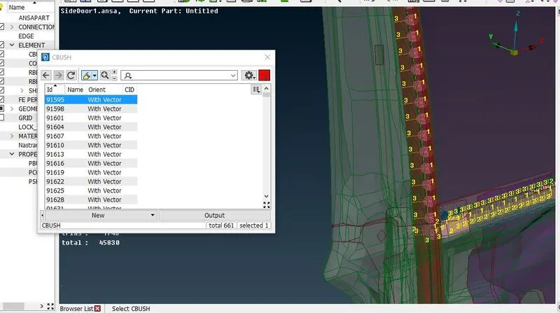
CBUSH elements oriented with respect to vector
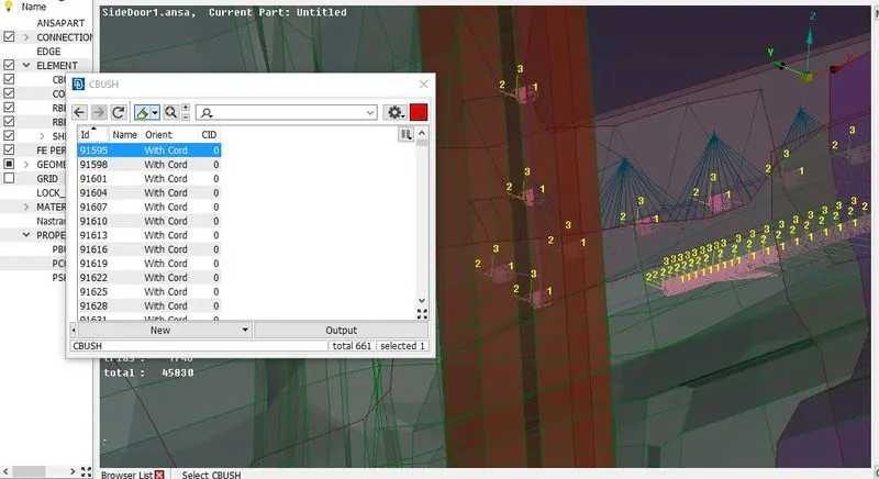
CBUSH elements oriented with respect to global co-ordinates
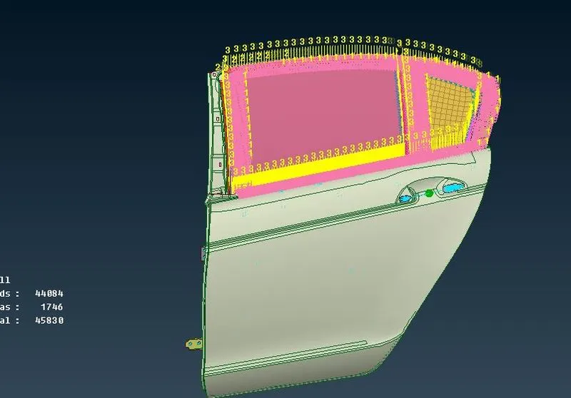
Final FE model with connections
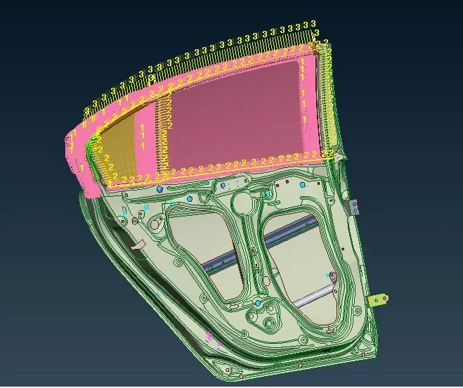
Final FE model with connections
Conclusion:
Successfully assigned suitable connection to the rear door car.
Learning Outcomes:
Assigning suitable connections such as RBE2, CBUSH, Weld connection.