Week 3
AIM: To cleanup the geometry of the Hood model and mesh the hood with the given quality criteria.
PROCEDURE FOLLOWED:
- Separate different parts in the model.
- Geometry cleanup
- Check for symmetry.
- Mid surface Extraction.
- Mesh the Mid surface as per the given quality criteria.
- Assign thickness to the meshed mid surface.
The above process is followed once the CAD model is imported into the ANSA module. The necessary UI modifications are done so that there is a clear visibility of its hot points, cons, faces etc.
1. Separate different parts:
Different parts in the CAD model are separated so that it gives a clear idea of the model that is to be meshed. For effortless selection of the separated part a "Lock View" is assigned to each of it.
2. Geometry Cleanup:
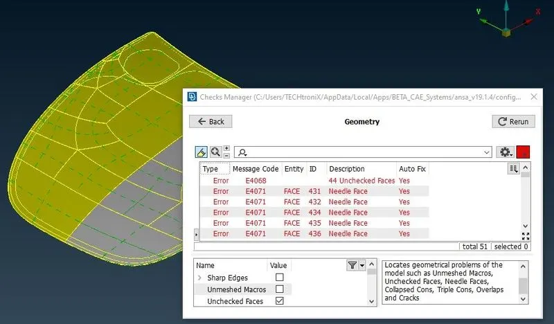
In this step each part is checked for its geometrical errors using the "Checks Geometry" command. This process has shown some errors such as needle faces, Unchecked Faces. These errors are eliminated using the Auto fix option. The TOPO module is used for geometry checks.
Geometry errors
The above figure shows the component with two different colours which defines that it is not properly oriented. This error is fixed using the "Orient" command available in the faces section of Topo module. This module provides us with numerous options to cleanup the geometry. Some of the options used are Release Cons, Delete Hot points, Topo, etc.
3. Check for Symmetry:
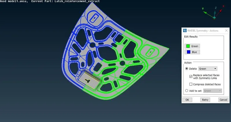
Parts that look symmetry are checked using the Rm.Dbl command by considering the symmetry plane. This command shows the unsymmetric areas with colour differentiation.
Symmetry demonstration
Green and Blue coloured region shows the symmetry. The inner hood is not symmetric in the front region. Hence the mid surface is extracted only on half of the symmetric surfaces and unsymmetric faces.
The same process is followed for outer part of the hood.
4. Mid surface extraction:
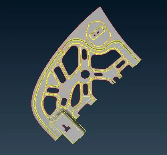
The mid surface is extracted using the Offset command by assigning the offset distance and direction. This command gives us the option for not deleting the original face. There is also another command "Mid surface" which automatically extracts the mid surface without the need for defining distance. But this option deletes the original face.
Mid surface Extracted
Geometry cleanup is again performed on the extracted mid surface and the orientation is finalized.
5. Mid surface meshing:
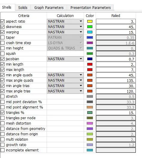
Once the extracted mid surface is geometrically cleaned meshing is performed on it. Hence the module is switched to MESH. Quality parameters are assigned which defines the element quality.
Quality Parameters
Element Length of 5 mm is assigned. Out of all the commands used for meshing, "BEST" command meshes macros using all alternative algorithms and keeps only the mesh of best quality. Even then the mesh fails the quality criteria and OFF elements appear.
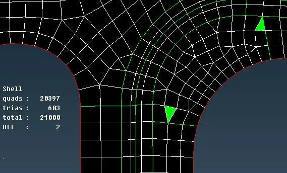
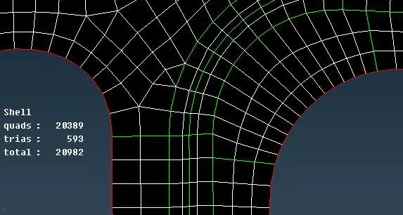
OFF elements developed OFF elements eliminated
The green coloured elements in the above figure defines that they fail in skewness parameter. Hence these failed elements are remeshed using the "reconstruct" command which remeshes the selected elements. Inorder to attain good mesh flow other commands such as split, swap, split quads, join, smooth, etc. are used. Surfaces can also be segregated to obtain a good mesh flow.
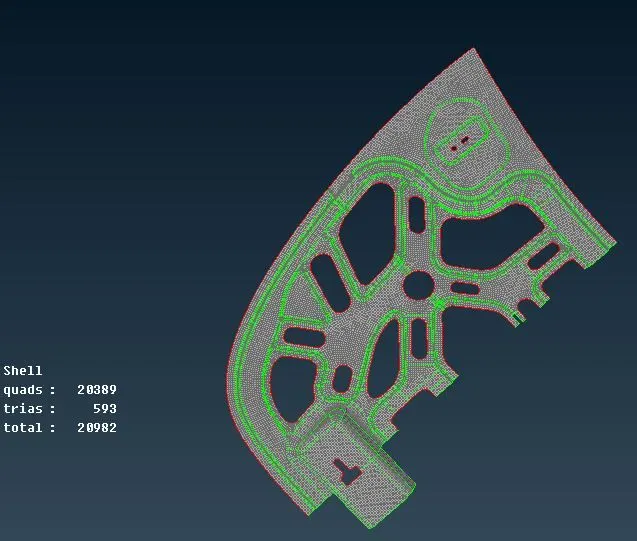
Meshed mid surface
The mid surface is meshed until the good mesh flow is attained along the assigned quality parameters. The remaining half is obtained using the Transform command which helps in creating the symmetric condition.
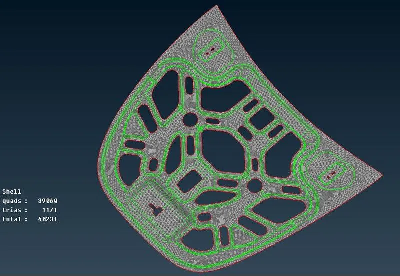
Symmetry assigned
The similar procedure is followed for all the separated parts to obtain a good mesh.
6. Assign Thickness
These meshed mid surfaces are now assigned their respective thicknesses using the Properties option. Different properties are created for all separated parts. each property is assigned to their respective part.
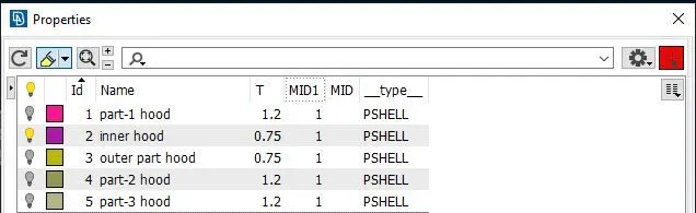
Property IDs with Thickness
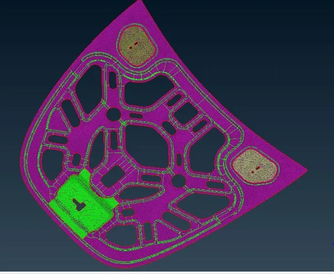
Mid surfaces with PIDs Applied
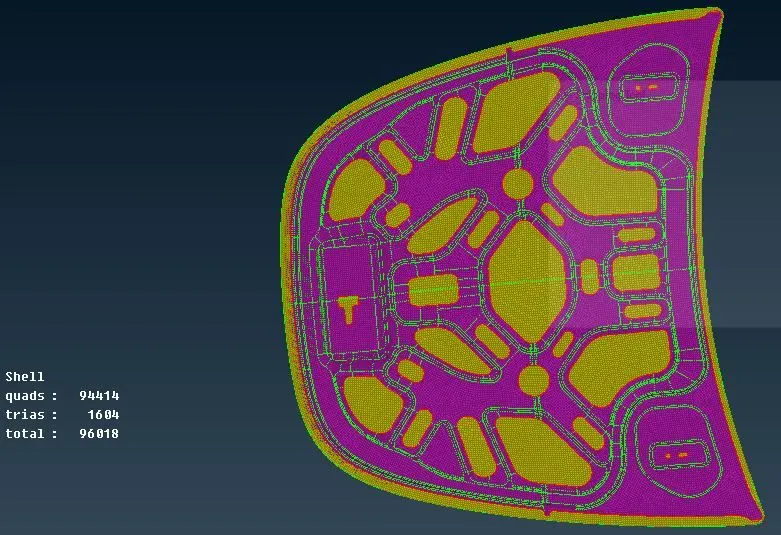
Completely meshed model with zero OFF elements
The Above figure shows completely meshed model with zero OFF elements and different properties assigned.
Conclusion:
Geometry of the hood model with 5 different parts is successfully cleaned. Mid Surface for each of the parts is perfectly extracted. Meshed with satisfying quality parameters.
Learning Outcomes:
Geometry Cleanup, Mid surface extraction, Shell meshing.