Week - 4 - 2D meshing for Plastic components
AIM: To cleanup the geometry of a plastic component (Bottle Cap), extract a mid surface and mesh it with the given quality criteria.
PROCEDURE FOLLOWED:
- Study the CAD model.
- Geometry cleanup.
- Mid surface Extraction.
- Mesh the Mid surface as per the given quality criteria.
- Assign thickness to the meshed mid surface.
The necessary UI modifications are made for clear visibility of hot points, cons, faces etc. The CAD model is studied for clear understanding of its geometry.
- Geometry Clean-Up
After a clear idea of the geometry is obtained, the CAD model is evaluated for its geometrical defects such as single cons (between two faces), unnecessary triple cons, etc. "Checks Geometry" command is used for evaluating after which it displayed needle edge defects that can be eliminated using the "Auto fix" command.
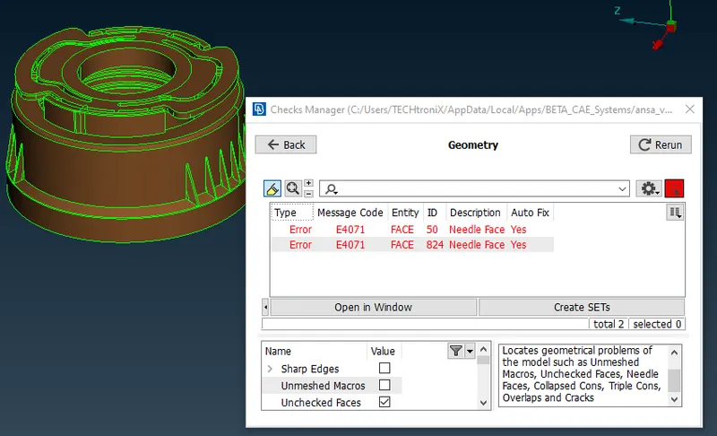
Geomtery Errors
- Mid surface Extraction
There are several commands for extracting the Mid surface of plastic components or castings such as "mid surface, middle, offset". Out of these "midsurface" command automatically extracts the mid surface of a solid body. But there are chances of developing some geometrical errors. This results in a bad mid surface. Sometimes due to the complexity of the geometry, this option might not even execute.
Hence, the mid surface needs to be extracted manually. The other two commands "middle (creates a middle face between two others), Offset (offsets faces)" are mostly used in extracting the midsurface.
During this process the mid surface of some faces su ch as ribs, threads etc might not be in contact with the other surfaces. These types of surfaces need to be extended to the other surfaces.
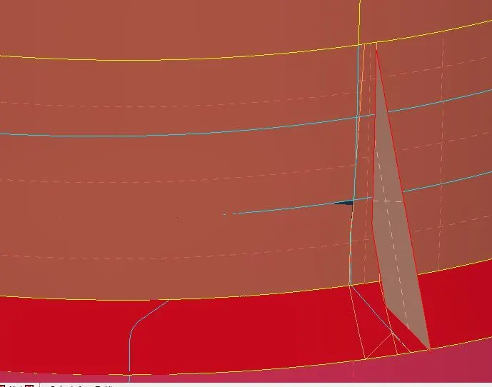
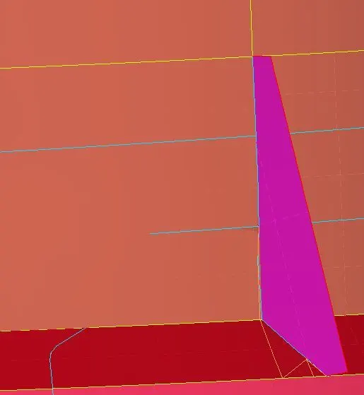
Rib Mid surface before extend Rib Mid surface after extend
"Intersect" command is used for defining intersection between the two groups of faces. This creates a triple con. Extra faces obtained during the extend process are deleted. A complete mid surface is obtained manually using these commands.
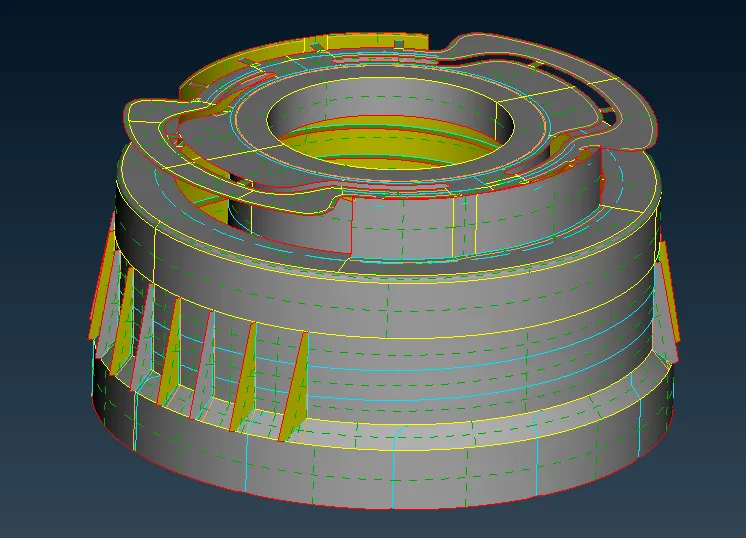
Mid surface Extracted
The above picture is a final mid surface achieved which differentiates single cons(red), double cons(yellow), triple cons(blue). This mid surface is again checked for topo errors and the orientation of the faces is rectified using the "orient" command.
- Mid surface meshing
The mid surface extracted meshed following the given quality criteria. The target length of 1 is assigned. Different quality parameters such as skewness, aspect ratio, jacobian, etc. are allocated. Quad elements are the most preferred type of elements. Certain meshing guidelines are followed such as:
- No tria elements near to free edges, holes, fillets.
- Tria elements are maintained less than 15%.
- Maintaining the Target element length.
- No rotating quads.
- No opposite Trias.
- Eliminating OFF elements.
- Good mesh flow.
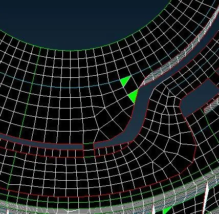
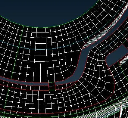
FE model with OFF elements FE model without OFF elements
OFF elements developed are mostly eliminated using various commands such as "reconstruct, split, swap, split quads, split X, smooth etc". A good mesh flow is also obtained.
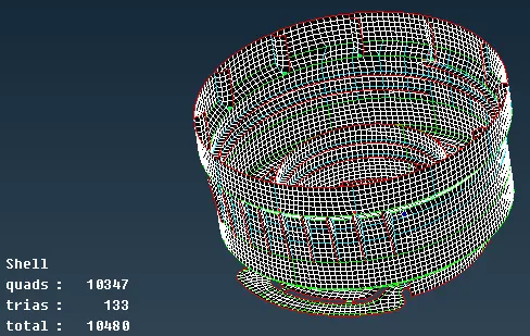
Meshed Mid surface
- Assigning Thickness
Once the complete mid surface is meshed, thickness is assigned. This part consists of different thicknesses at different sections. Hence a property id is created with a separate thickness and is assigned to the respective elements. Random colours are applied to differentiate.
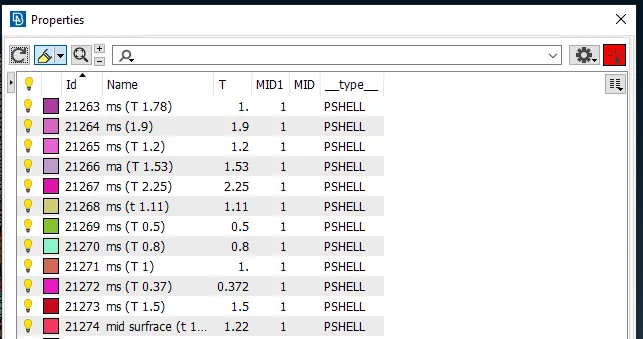
Property ids with different thicknesses
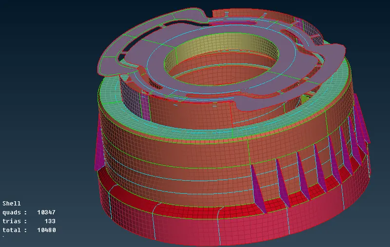
Meshed mid surface with different property ids assigned
Once the property ids are applied "Draw shells as Solids" command is activated. This command displays all shell elements as solids with respect to their thicknesses assigned.
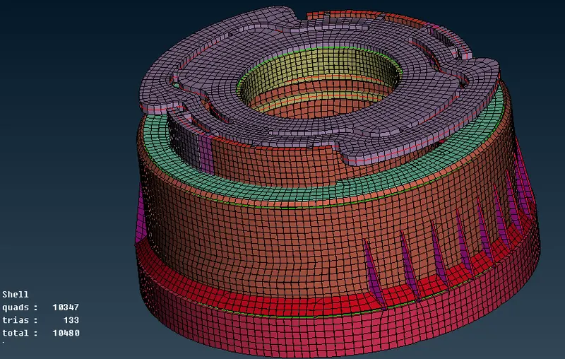
FE model with thickness enabled
- Conclusion
Mid surface of a plastic component (Bottle Cap) is perfectly extracted manually and successfully meshed within the given quality parameters.
- Learning Outcomes
Mid surface extraction of castings, Shell Meshing, Thickness assigning.