Week 6 - Creating connection for Rear door
Objective:
The given Rear door FE model, Create and Apply different PIDs for different components. Perform suitable connections.
Procedure:
1.Assigning Property ID
Import Model – Open the given model (sideDoor.ansa) in ANSA – Rear door of same property ID.
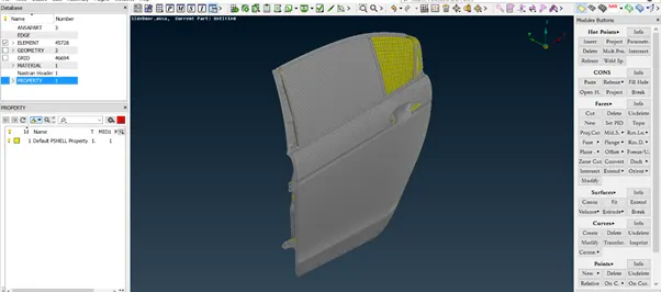
Separate PIDs was assigned to each part of the model.
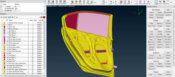
- Connections.
A) Bolt Connection & RBE2
- (Topo -> Points -> On COG (Edges)) create centre of gravity point of the Door Hinges’ hole
- Convert the COG point into Bolt Connection (Assembly-> convert -> 3D point)
- Assign the parameters to the bolt (Assembly-> Connection Manager) like P1, P2, P3 are the components which are to be bolted together, Zones – In/out & Check/uncheck Body accordingly
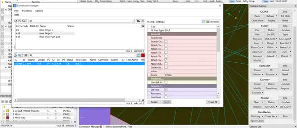
With Body:
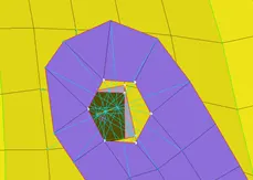
Without Body:
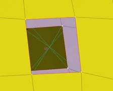
B) RBE2 Connection (Door Hinge – with rotation constraint)
- Nastran -> Elements -> RBE2 (Many nodes) to create connection on door hinge upper and lower parts.
- Nastran -> Elements -> RBE2 (Two nodes) to create a connection between the Upper and lower part by selecting two nodes i.e., master node of both parts, while assigning change the centre of motion to 12345 so that the door is constrained to the direction i.e., Z-axis
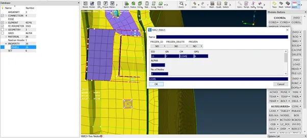
C) Spot Weld Connection
- (Topo -> Points -> On COG (Edges)) create a center of gravity point where the spot to be made
- Convert the COG point into Spot weld connection (Assembly-> convert -> 3D point)
- Assign the parameters to the spot weld (Assembly-> Connection Manager) like P1, P2 which are to be welded together, RBE3 pin flags (123456) and Create a new property for Weld (PSOLID ID).
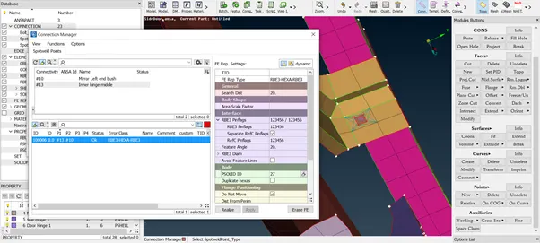
D) Door Handle Connection with CONM2
- Nastran -> Elements -> RBE2 (Many nodes) to create connections on door handles in both holes.
- Nastran -> Elements -> RBE2 (Many nodes) to create a connection between both parts by selecting two nodes i.e., master nodes
- Nastran -> Elements -> CONMi (CONM2) to add mass (M) at the master node connecting both (100 gm in tonnes (0.0001))
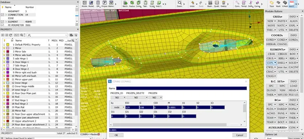
E) Mirror Bush Connection
- Mesh -> Permeters -> Feat2Curve, Select the border of the mirrors to create curves.
- Convert those curves into Spot lines (Assembly-> convert -> curves)
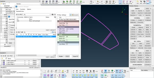
- Assign parameters to the spot lines (Assembly -> Connection manager) like P1, P2 which are to be connected with bush, S (space) 10, check to Keep all branches and Create a new property for bush PBUSH ID
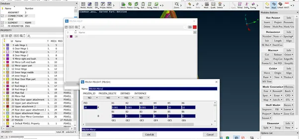
- Keep the following stiffness while defining PBUSH ID
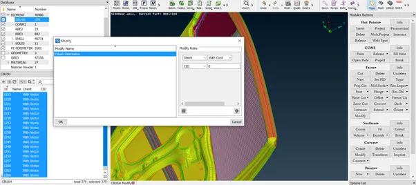
- Align the local co-ordinates of the bushes to the global co-ordinates using modify, Set Orient – With cord & CID – 0 selecting all CBUSH elements (Database -> Element -> CBUSH)
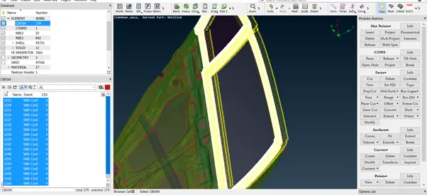
- After aligning bushes with global coordinates.
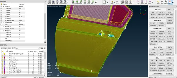
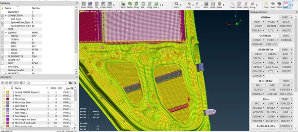
Final Model Image:
Learning Outcomes:
Performing Suitable connections
Conclusion:
In the given Rear Door, suitable connections are made successfully.