Week 6 - Creating connection for Rear door
Aim:
To create the connection of the given meshed component. To create a product without failing with the help of ANSA.
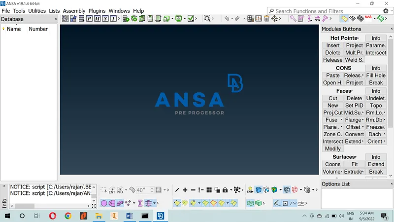
LAYOUT OF THE ANSA
Given data:
Meshed component – Rear Door.
Steps to follow in ANSA.
- Import cad geometry.
Go to file > Open > Browse the location of the given CAD model > Select it click on Enter.
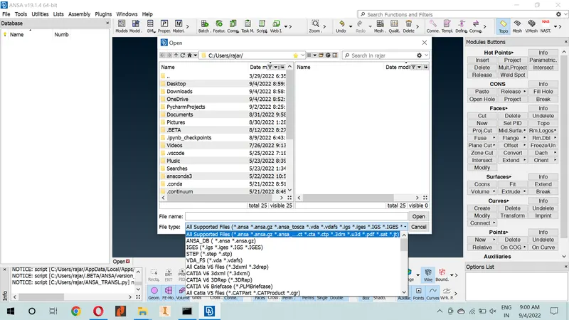
Import cad geometry
- Geometry cleanup.
Go to Toolbar > checks > Geometry > Visible > Execute > Check for the green tick beside geometry > close the window.
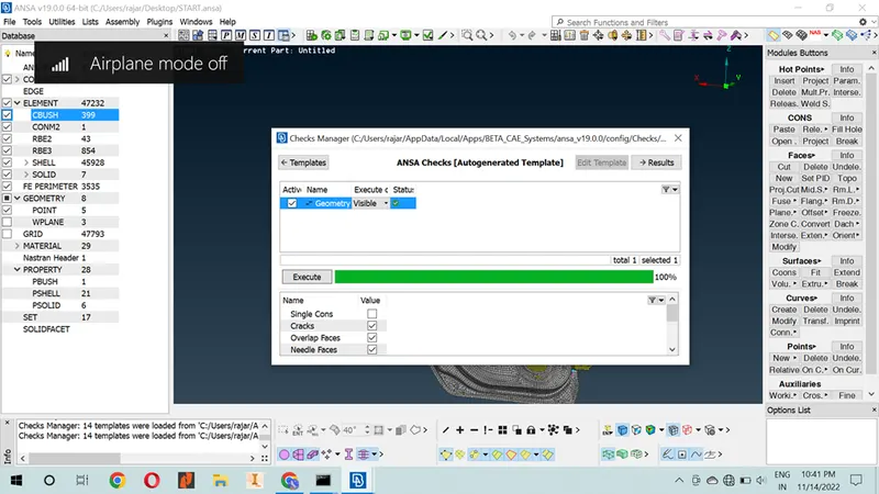
Geometry cleanup
CREATE PROPERTIES: It can be use to identified and given input date for connection.
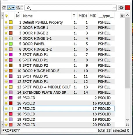 CREATE PROPERTIES
Connection:
A connection is a geometric constraint that defines how a part is connected to another part in an assembly model. Connectors are used in FE modelling to represent the kinematic conditions of a system that are physically present. Connectors in FE modelling include welds, bolts, adhesives, rigids, etc.
Procedure to create connection:
Weld connection:
Welded connections are connections whose components are joined together primarily by welds. Welds can be classified according to: Types of welds: groove, fillet, plug, seam weld, and slot welds. Positions of the welds: horizontal, vertical, overhead, and flat welds.
seam welding: Seam welding can be used to make gas- or fluid-tight joints in a variety of sheet metal fabrications. Steel fuel tanks for motor vehicles and door for a car are a prime example. It is also used in making tin cans, steel drums and domestic radiators.
The given model is sheet metal. Mostly sheet metal using seam weld connection.
Step-1: Measure the length of the seam weld.
Step-2: Create the length in to curve. By help of this command
Topo module > curve tab > cone2curve command > click the cone. (Turn on curve visible)
Step-3: The seam weld data automatically stored in ANSA. We just identified and mark the location of the seam weld. By help of convert option.
Assemble manager > convert option. It creates a new window.
Convert > curve (select we created curve) > connection type > seam weld > ok
Step-4: Connection manger appears for seam weld. To set the connection manager FE REP type in overlap shell and select the P1 & P2. P1 & P2 is selection of the seam weld area and set the length of the seam weld and if you need to add any date for it, you will, improve the seam weld.
This step is creating the seam weld connection.
Spot welding: Spot welding (also known as resistance spot welding) is a resistance welding process. This welding process is used primarily for welding two or more metal sheets together by applying pressure and heat from an electric current to the weld area.
The given model is sheet metal. Mostly sheet metal using spot weld connection.
Step-1: Topo module > point tab > ON COG command > select the cone & click middle button on mouse. (In this option create a MIDPOINT)
Step-2: The spot weld data automatically stored in ANSA. We just identified and mark the location of the spot weld. By help of convert option.
Assemble manager > convert option. It creates a new window.
Convert > MIDPOINT (select we created MIDPOIINT) > connection type > spot weld point > middle click on the mouse.
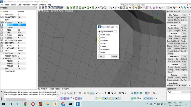
Step-4: Connection manger appears for spot weld. To set the connection manager FE REP type in RBE3-HEXA-RBE3 and select the P1 & P2. P1 & P2 is selection of the spot weld area and, set the length of the spot weld and if you need to add any date for it, you will, improve the spot weld.
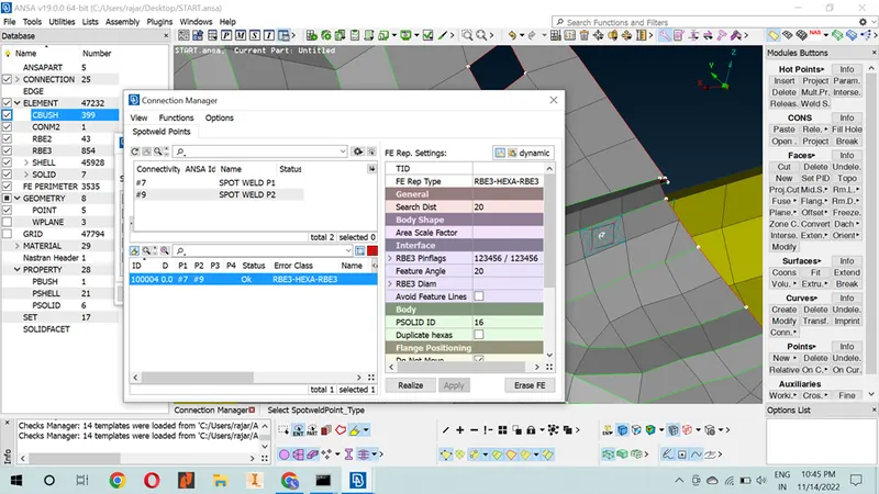
NOTE: PSOLID ID: CREATE THE NEW PROPERTY BY HELP OF SHOTCUT KEY - SHIFT + / .
SELECT P1 & P2 : CLICK LEFT BUTTON ON MOUSE > MODIFY AREA APPEARED > CLICK F1 > SELECT THE PART OF P1 OR P2.
This step is creating the spot weld connection.
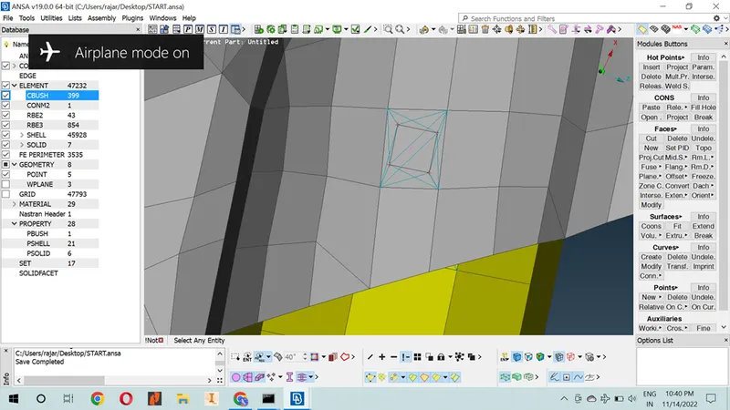
FINAL RESULT OF THE SPOT WELD
NOTE: IN THIS MODULE WE USING ONLY SPOT WELD.
Bolt Connection:
Bolted connections are a type of structural joint used to join two or more structural components in a steel structure using bolts. Bolts are a form of threaded fasteners which has a male thread and preformed matching female thread, such as nuts.
The command for creating bolt in the hole area is NASTRAN FUNCTION
Step-1: Element module > RB2> MANY / TOW NODES > New window appears (select and click OK).
Step-2: Topo module > point tab > ON COG command > select the cone & click middle button on mouse. (In this option create a MIDPOINT)
The bolt weld data automatically stored in ANSA. We just identified and mark the location of the bolt weld. By help of convert option.
Assemble manager > convert option. It creates a new window.
Convert > MIDPOINT (select we created MIDPOIINT) > connection type > BOLT> middle click on the mouse.
Step-4: Connection manger appears for spot weld. To set the connection manager FE REP type in BOLT and select the P1 & P2. P1 & P2 is selection of the bolt area and, set the length of the bolt and if you need to add any date for it, you will, improve the bolt connection.
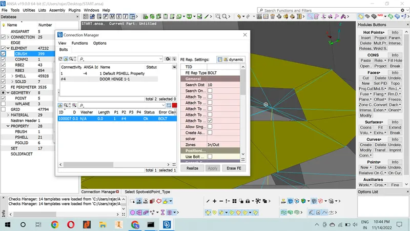
FINAL RESULT OF THE BOLT CONNECTION
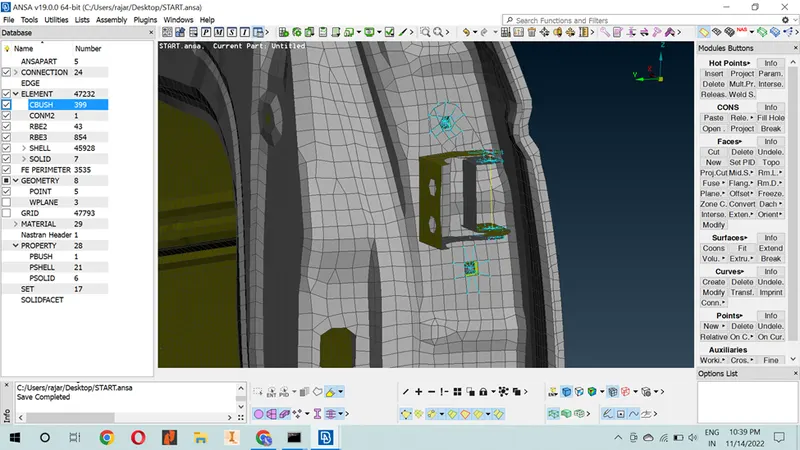
CONMI- Concentrated mass element connection
The use of the CONM2 entry for Autodesk Explicit has been modified from the original CONM2 entry for Nastran. If the grid point, G, listed on the entry is the same as a reference node for a rigid body, the mass properties on the CONM2 entry are applied to a rigid body.
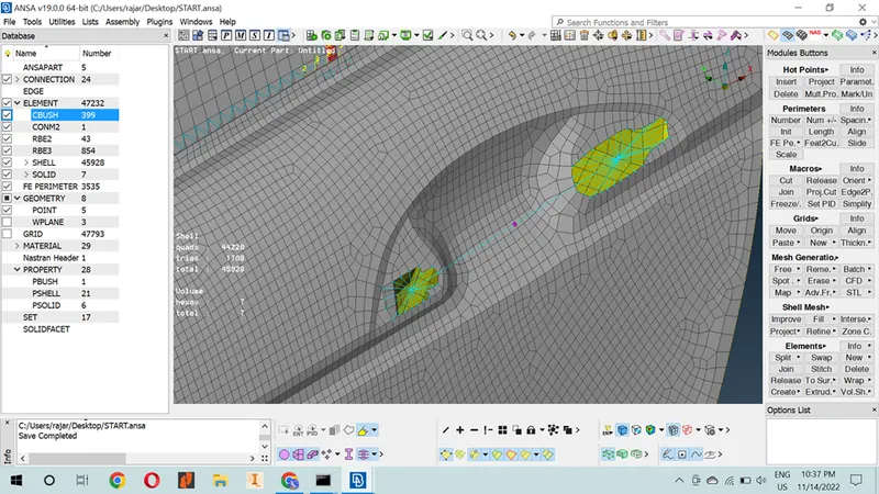
Adhesive or seal strip Connection:
Adhesive bonding is a process in which joining between two or more parts is accomplished by the solidification or hardening of a non-metallic adhesive material, placed between the faying surfaces of the parts
Step-1: Create the outer region in to curve. By help of this command
Topo module > curve tab > cone2curve command > click the cone. (Turn on curve visible)
Step-2: The spot line data automatically stored in ANSA. We just identified and mark the location of the spot line. By help of convert option.
Assemble manager > convert option. It creates a new window.
Convert > curve (select we created curve) > connection type > spot line > ok
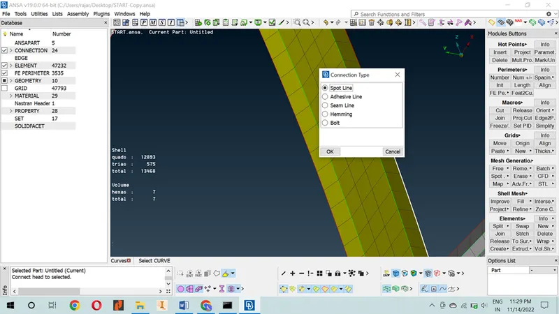
Step-3: Connection manger appears for seam weld. To set the connection manager FE REP type in RBE3-CBUSH-RBE3 and select the P1 & P2. P1 & P2 is selection of the Adhesive area and set the length and if you need to add any date for it, you will, improve the Adhesive.
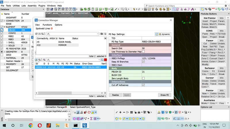
Set CBUSH orient to with code & CID to 0 – it help to change in the axis.
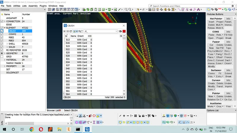
AXIS CHANGED
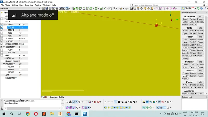
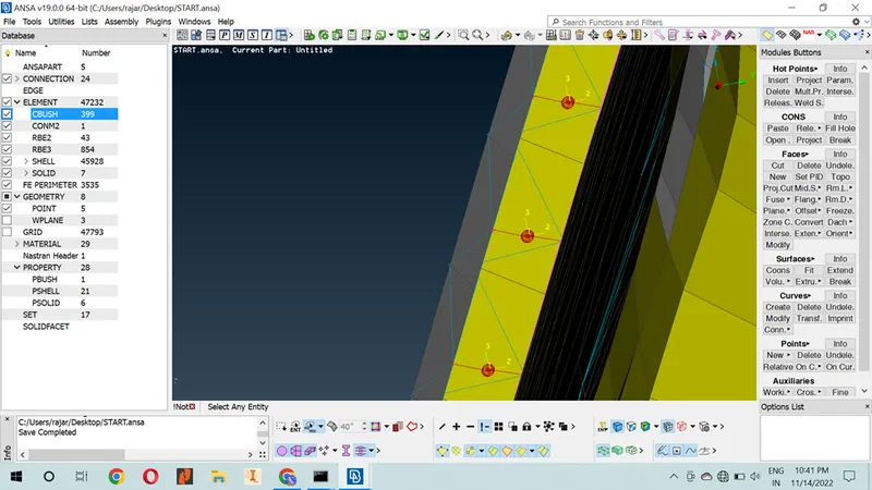
FINAL RESULT OF THE RUBBER JOINT CONNECTION.
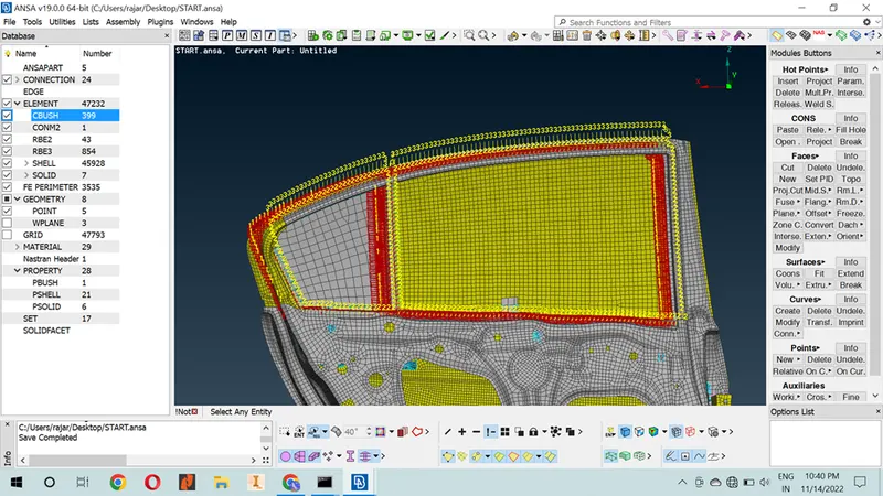
FINAL RESULT OF THE CONNECTION
RESULT:
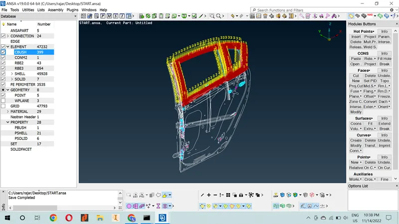
FINAL RESULT OF THE WIRE LAYOUT
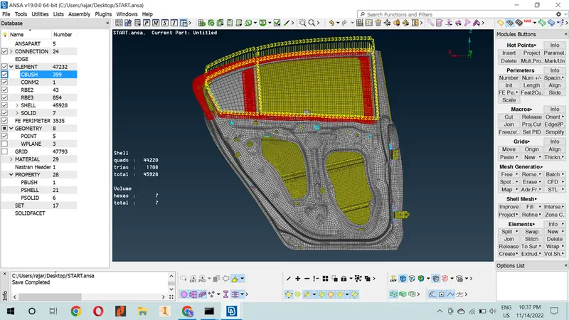
FINAL RESULT OF THE CONNECTION.
LEARNING OUTCOMES:
To increase the performance on connection of seam weld and bolt, now I am able to achieve connection in any model.
Now I am easily Identify the connection area and create connection.
To increase the working speed in ANSA.
In the end of the challenge, I learn lot of commands and shortcut key.
CONCLUSION:
Connection of the given model were successfully done. All the features in the model are captured properly with good mesh flow.