Week- 5 - Solid meshing
Aim:
To create a MESH of the given component by using given quality criteria. To create a product without quality criteria failed by the help of ANSA.
Given data:
- CAD model - Solid meshing for Rearview mirror.
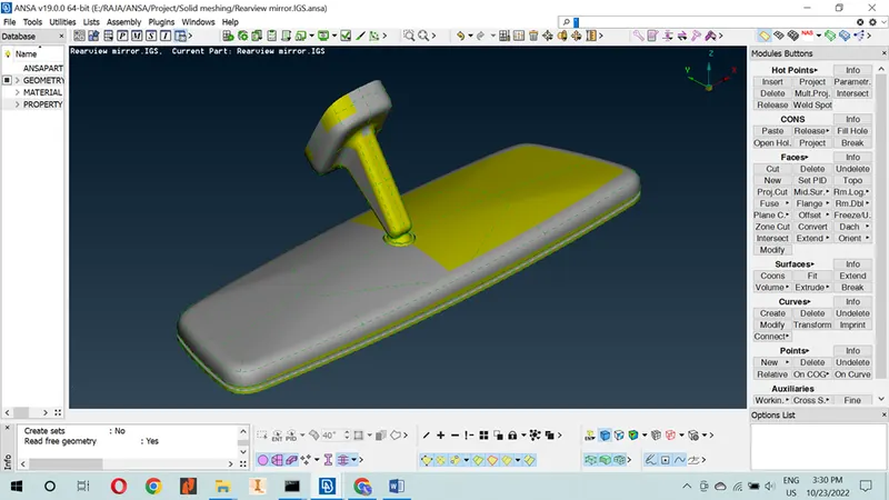
- Quality criteria – with the help of achieve the quality.
GIVEN DATA / INPUT
|
Quality Criteria for Shell Elements |
||
|
S.NO |
QUALITY CRITERIA |
VALUE |
|
1 |
Target/Avg length |
1 |
|
2 |
Min. length |
0.5 |
|
3 |
Max. length |
3 |

Steps to follow in ANSA.
- Import cad geometry.
Go to file > Open > Browse the location of the given CAD model > Select it click on Enter.
- Geometry cleanup.
Go to Toolbar > checks > Geometry > Visible > Execute > Check for the green tick beside geometry > close the window.
- Shell or solid meshing:
Mesh parameter > Enter target length, Min. target length & Max. target length.
Measure the perimeter length - GO to perimeter > Length
- Element quality check.
Click quality criteria / press F11 (shortcut key), apply the given input value.
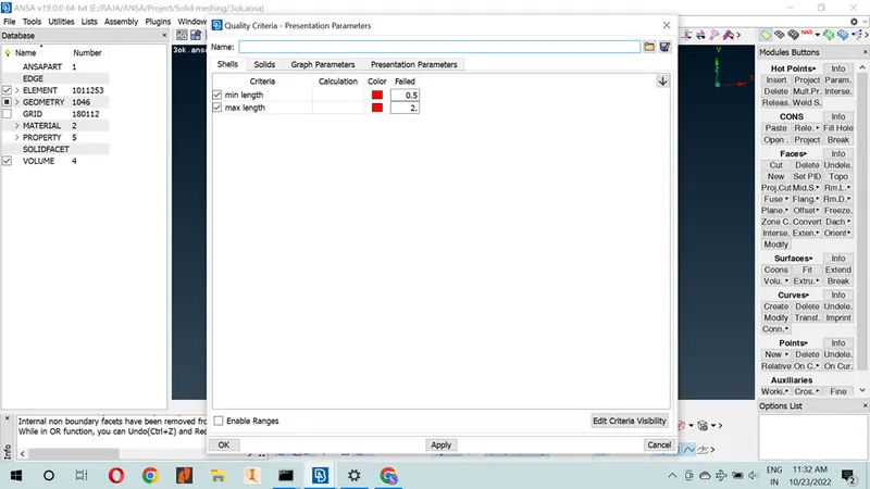
Quality Criteria for Shell Elements
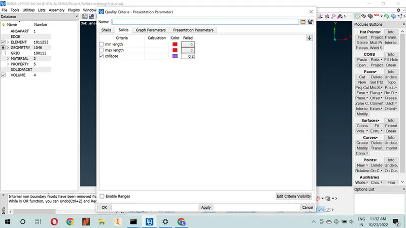
Quality Criteria for solid Elements
- Mesh improvement: To improve the mesh, the result will be better.
- Apply load & Boundary condition: It depends on the requirements we need.
- Export input file: Export the result.
Procedure:
Import the cad geometry:
Go to file > Open > Browse the location of the CAD model > Select it click on Enter.
The given cad model is sheet metal – REARVIEW MIRROR.
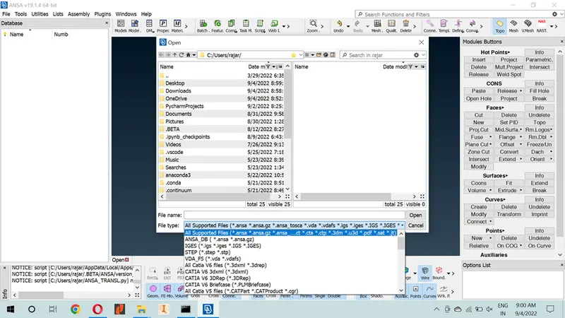
Import cad geometry
Geometry cleanup:
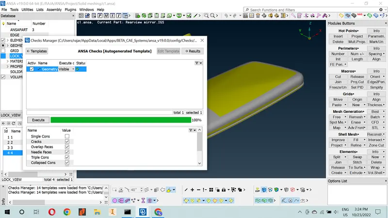
Go to Toolbar > checks > Geometry > Visible > Execute > Check for the green tick beside geometry > close the window.
Geometry cleanup
Execute to run the geometry cleanup. If there are any geometry errors, right click on the mouse on the highlighted errors and select auto-fix (automatically edit geometry issue) or edit manual as your wish.
Shell or Solid meshing:
Before the solid mesh, we can check the model thickness with the help of a measurement option and decide whether the solid mesh is necessary or not. If the model thickness is more than 5mm, then shell mesh is not needed. The shell mesh process is deferring from the solid mesh. So, we check and choose what we perform in this model.
This given model is more than 5mm. So, we use solid mesh.
For measurement: Go to measure > Nodes > click on any two hot points to get the value
Solid meshing: (Two steps involved in the meshing process)
Step 1: We did the surface mesh with the help of batch mesh parameters.
Step 2: Create the volume of the model by help of the volume mesh module.
Surface mesh - The Batch Mesh Parameter command is using mesh on the surface. In this command, we have to create the new meshing parameters. The parameters are mesh parameters and quality criteria. Mesh parameter > Enter target length, Min. target length & Max. target length.
Quality criteria - Click quality criteria / press F11 (shortcut key) to open quality criteria window. Apply the given input and save the Quality criteria values.
Use mesh generation to mesh the surface. I am using two types of mesh in this model, tria and ortho tria mesh. We have a curved region for the given model. So, I use Ortho tria mesh used in the curved region. It gives a better result and a perfect shape of the surface.
Volume mesh - In this, mesh is separated by unstructured mesh and structured mesh. Unstructured mesh is used in the tetra algorithm. The Tetra algorithm is used for the tetra meshed model. Structured mesh is used in the hexa algorithm. The Hexa algorithm is used for the hexa meshed model.
Note: We use tetra mesh. So, we use unstructured mesh tab.
In this unstructured mesh tab, it has five types of algorithm. Now we use TETRA FME. This command is used to convert the solid mesh into volume mesh.
Now the volume mesh is generated automatically in a model. After finishing the mesh, check the quality of the mesh. To hide mode from shadow mode, it shows clearly and there are any errors we need to fix by help of the shell mesh tab (Reconstructs, smooth option), elements tab (split, join, swap option), grids tab (Move & paste option).
If the mesh fails in quality criteria, we will re-generate the mesh with the help of shell mesh topo. The shell mesh topos have options to increase the quality of the model with the help of smooth, improve, reconstruct, split, join, cut options.
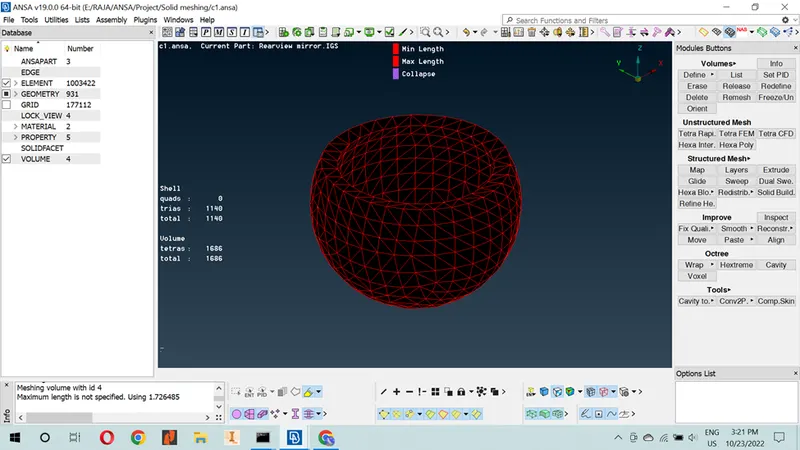
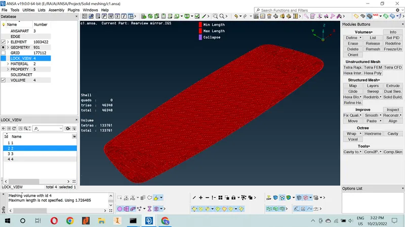
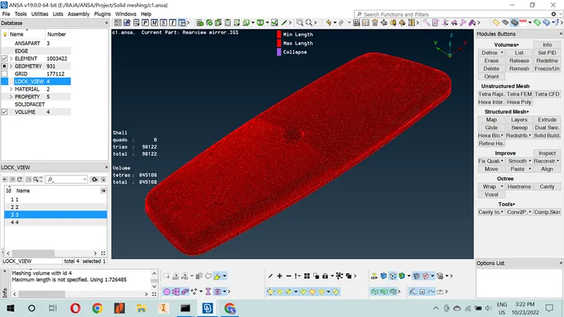
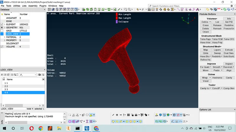
NOTE: Mesh flow should be Good, no rotating quads and Opposite trias should present in the model.
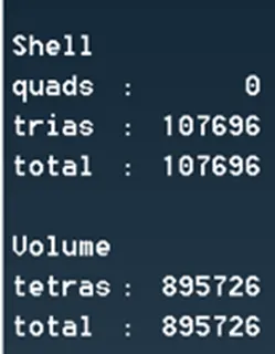
DETAIL OF THE ELEMENT:
LEARNING OUTCOMES:
To increase the performance on solid mesh, now I am able to achieve solid mesh in any model.
To increase the mesh quality with the help of mesh module tools, now I am able to work with tool flow.
Now I am easily Identify the quality error and resolve the error.
In the end of the challenge, I learn lot of commands and shortcut key.
CONCLUSION:
Geometry cleanup and solid meshing of the given model were successfully done. And all the elements pass the quality criteria. All the features in the model are captured properly with good mesh flow.