Week 3 - 2D meshing for sheet metal
Aim:
To check the geometry cleanup, mid-surface, shell mesh and draw shell as solid for the given component by use of ANSA Pre-processor.
ANSA Pre-processor V19.1.4
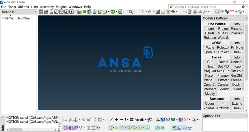
WHAT IS ANSA? :-
ANSA is a Computer-aided engineering tool for Finite Element Analysis and CFD Analysis widely used in the automotive industry. It is developed by BETA CAE Systems. The software is distributed worldwide by a number of BETA CAE Systems subsidiaries and business agents. In the United States, it is distributed by Beta CAE Systems, USA, based in Farmington Hills, Michigan.
ANSA maintains the association between CAD geometry and the FE mesh. This means that the FE meshes are better representations of their geometric parents. Also, it is easy to maintain and update any changes in the geometry by simply reworking the updated area instead of recreating the FE from scratch.
It carries several proprietary algorithms for meshing suitable for both CFD and structural models. ANSA was initially standing for \'Automatic net generation for structural analysis\', but the software has gone beyond that very quickly. ANSA has broadly six menus which are used to do various activities those are: TOPO MESH, VMESH, DECK-SOLVER, MORPH, HBLOCK.
(source: wiki)
Given data:
- CAD model.
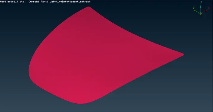
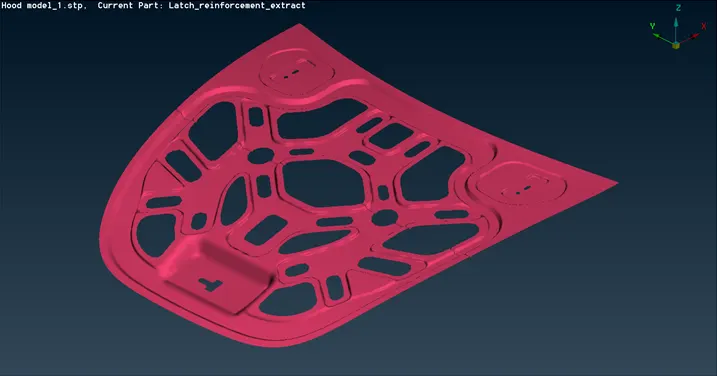
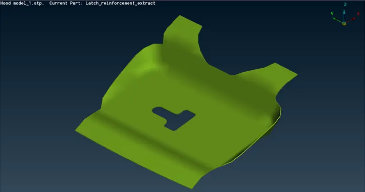
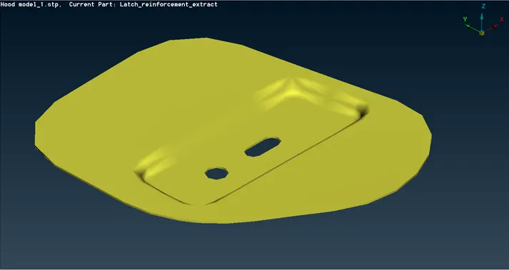
HOOD PANEL
- Quality criteria.
Each and every product has a set of quality checks. If the quality fails in this model, the boundary condition and applying loads is not possible to apply, so to check the quality criteria for the reason.
The quality criteria are entered as input data. The elements should be maintained in the given input. If the quality is not maintained, there will be a failing in quality.
GIVEN DATA / INPUT
|
S.NO |
QUALITY CRITERIA |
VALUE |
|
1. |
Target/Avg length |
5 |
|
2. |
Min. length |
2 |
|
3. |
Max. length |
7 |
|
4. |
Aspect ratio |
3 |
|
5. |
Warpage |
15 |
|
6. |
Skewness |
45 |
|
7. |
Jacobian |
0.7 |
|
8. |
Min. quad angle |
45 |
|
9. |
Max. quad angle |
135 |
|
10. |
Min. Tria angle |
30 |
|
11. |
Max. Tria angle |
120 |
|
12. |
Tria percentage |
15 |
Methodology:
- Import cad geometry.
- Geometry cleanup.
- Mid surface / Skin generation.
- Shell or solid meshing.
- Element quality check.
- Mesh improvement.
- Apply load & Boundary condition.
- Export input file.
Import cad geometry:
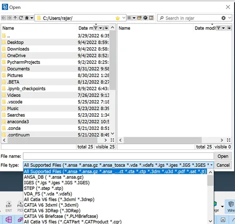
Import the given CAD model into ANSA. In ANSA, we can import all the CAD Software file formats.
Geometry cleanup:
- After imported cad-model to clean up the cad geometry.
- The main intention of Geometry clean-up is to eliminate single CONS and Reduce triple CONS as many as possible.
- In this model there are lot of patches and Geometry intersections to clear.
- Geometry check-up is done to check whether there are any errors in the model like Unclosed faces, Super Imposing faces, etc.
Mid surface / Skin generation:
- Mid surface is used to reduce the difficulty in CAD models and its accurate simulation results in short time. Mid surface is usually placed on the midplane of the part.
- Thickness is assigned mathematically, rather than geometrically. CAD geometry usually comes as a solid part, or a series of surfaces defining a volume.
- Mid surfacing creates a layer of surfaces on the midplane which can be directly meshed.
Note: Mid surface is only used for shell mess. Choose shell or solid mesh we can use in this modal.
Shell or solid meshing:
Shell or solid mesh depends upon the product. The sheet metal component and minimum thickness area should be shell mesh. The casting, molding and critical areas should be in solid mesh. In this project, I use shell mesh for meshing the given model since it is a sheet metal component.
Element quality check.
- The shape of Elements in FE Analysis must be distorted from their Ideal shapes when meshing the irregular or complex geometric shapes. Every element is designed to work properly within a certain range of shape distortion.
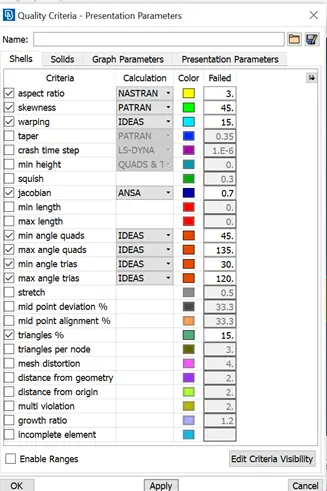
- The given quality criteria values have been entered in quality manager (shortcut key: F11). Above we mention the input valve in the given data.
Mesh improvement.
After quality checking and improving the mesh or any changes in quality, this stage is mesh improvement. Mesh improvement helps to improve the quality of the mesh element.
Apply load & Boundary condition:
Applying load and boundary condition fully depends on the requirement we need. After applying load and boundary conditions, the result will take time to solve the problem (time depends on mesh and size of the model). We can take the result all the way we need by help of the Export input file.
Procedure:
Import the cad geometry:
- Go to file > Open > Browse the location of the CAD model > Select it click on Enter.
- The given cad model is sheet metal – Inner and Outer hood panel.
Geometry cleanup:
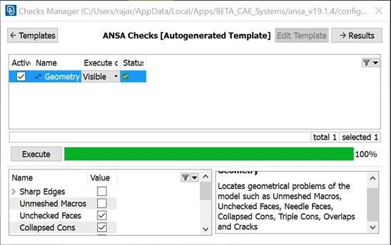
Go to Toolbar > checks > Geometry > Visible > Execute > Check for the green tick beside geometry > close the window.
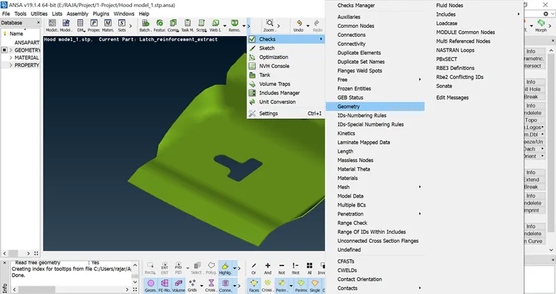
Execute to run the geometry cleanup. If there are any geometry errors, right click on the mouse on the highlighted errors and select auto-fix (automatically edit geometry issue) or edit manual as your wish.
Mid surface:
- Before the mid surface we can check the model thickness by help of measurement option and decide whether the mid surface is necessary or not. If the model thickness is larger, casting or molding model is not need mid surface.
- For measurement: Go to measure > Nodes > click on any two hot points to get the value
- For manual offset: In Topo module > Faces tab > click offset for manual skin generation & select faces and do middle click.
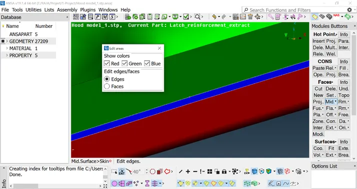
- For auto skin (auto mid surface): In Topo module --> Faces tab --> click mid surface --> Skin for auto skin generation & select the entire component & middle click.
Then the edit area tab will open. Now check with coolers.
- Red - bottom surface
- Blue - middle (thickness part)
- Green - top surface
Quality criteria:
- Click quality criteria / press F11 (shortcut key) to open quality criteria window.
- Apply the given input and save the Quality criteria value.
Shell meshing:
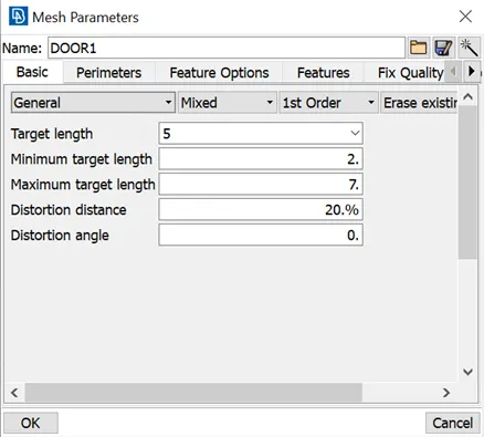
Mesh parameter > Enter target length, Min. target length & Max. target length.
- Measure the perimeter length - GO to perimeter > Length
- New window open > select perimeter > select the entire mid surface geometry
- New tab is open > enter the value > ok
- The perimeter is like a hot point. The hot point is increased. We can easily split the mid surface. Split the mid surface and mesh the mid surface separately, it helps to get a better result.
Meshing: Go to Mesh generation > best > select the surfaces to be meshed & middle click the mouse to confirm
Now the mesh is generated automatically in a selected area. After finishing the mesh, check the quality of the mesh. To hide mode from shadow mode, it shows clearly and there are any errors we need to fix by help of the shell mesh tab (Reconstructs, smooth option), elements tab (split, join, swap option), grids tab (Move & paste option).
Mesh generation
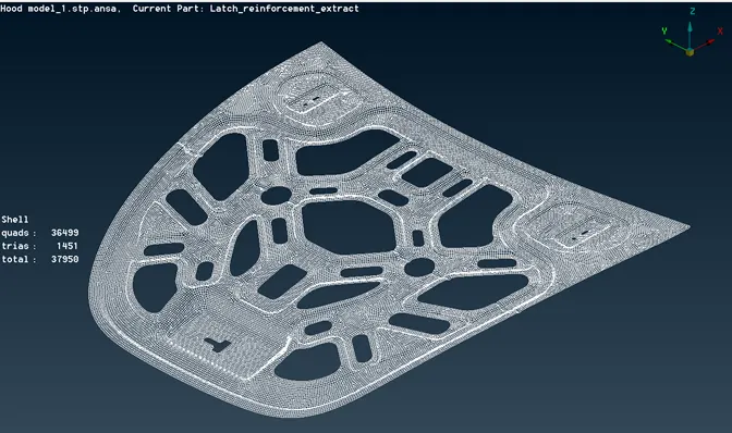
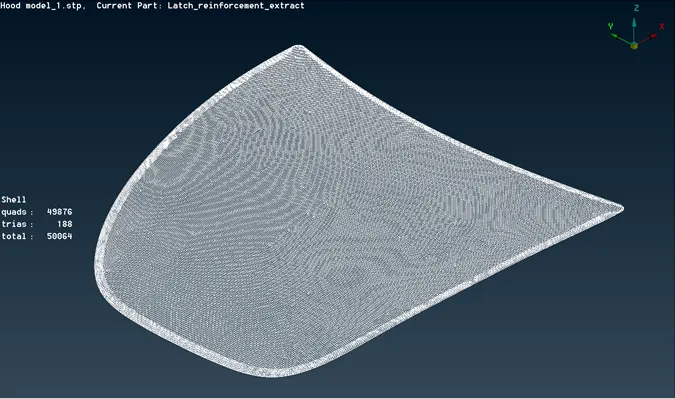
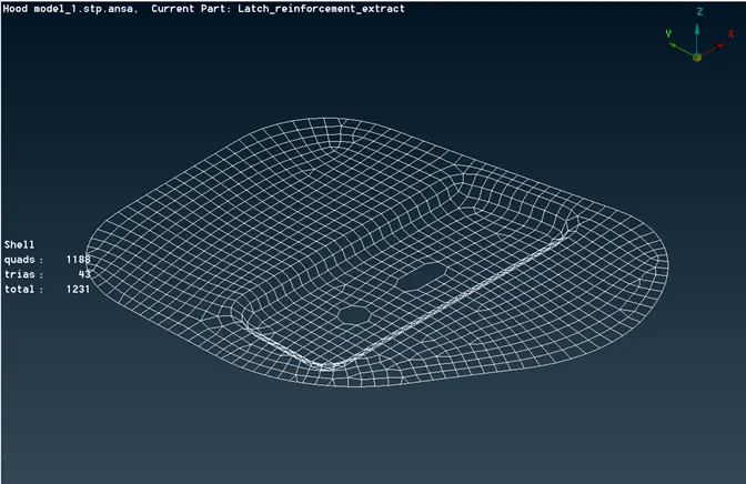
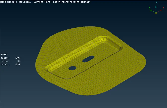
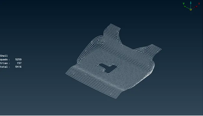
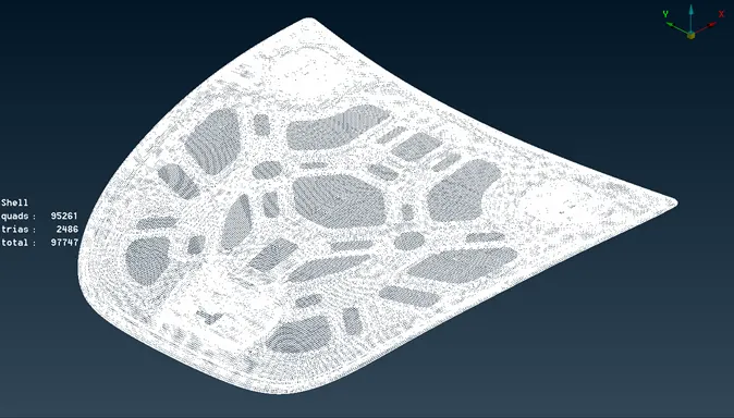
Note: Mid surface of component should be correct, Mesh flow should be Good, no rotating quads and Opposite trias should present in the model. Trias near to free edge or holes or on the fillets should be eliminated.
Draw shell as solid:
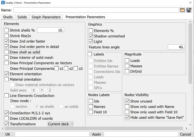
- Draw shell as solid is used to convert the mid surface as a solid and check the PID as assigned or not.
- For Draw shell as solid: Go to Quality criteria (short cut key - F11) > presentation parameters > Select Draw shell as solid > click OK
For PID: Go to topo module > Faces > Set PID > Faces/shells (In selection window) > select the mid surface geometry > Now property window will open & the PID will be created for the mid surface.
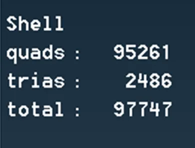
DETAIL OF THE SHELL ELEMENT:
LEARNING OUTCOMES:
- To increase the performance at mid-surface, now I am able to achieve mid-surface in a complex sheet metal.
- To increase the mesh quality with the help of mesh module tools, now I am able to work with tool flow.
- Now I am easily Identify the quality error and resolve the error.
- In the end of the challenge, I learn lot of commands and shortcut key.
CONCLUSION:
Geometry cleanup, mid surface extraction, and shell meshing of the given hood model were successfully done. And all the elements pass the quality criteria. All the features in the model are captured properly with good mesh flow. Tria concentration is kept low.