Week 6 - Creating connection for Rear door
AIM:
For the given car side door, different PID for each part to be assigned and necessary connections to be applied.
PROCEDURE:
STEP 1:
Importing the given model into ANSA using FILE-OPEN-SELECTING THE FILE options.
STEP2:
Assigning separate PID for each part by
- Selecting INOT option to isolate single part.
- Selecting TOPO – FACES – SET PID – MACRO – SELECTING THE FE – NEW – ENTERING THE NAME – DOUBLE CLICK, Then the PID will be created.
- Same procedure is continued until to create PID for all the part.
STEP 3:
Connections between the window and door.
- Firstly, the window part is isolated using INOT option.
- Creating a curve at bottom of the window using TOPO – CURVE – CREATE option and enabling FEATURE option.
- After creating the curve, the curve is assigned as SPOT WELD by selecting at TOP PANEL-CONNECTIVITY – CURVE – SELECTING THE CURVE – MIDDLE CLICK – SPOT WELD – OK.
- Selecting CONNECTION MANAGER – SELECTING THE CURVE – MIDDLE CLICK.
- Entering the spot distance value and assigning P1 and P2 using F1 key.
- Going to FE type options and selecting FE REP TYPE as RBE3-CBUSH RBE3, search distance -as per our need.
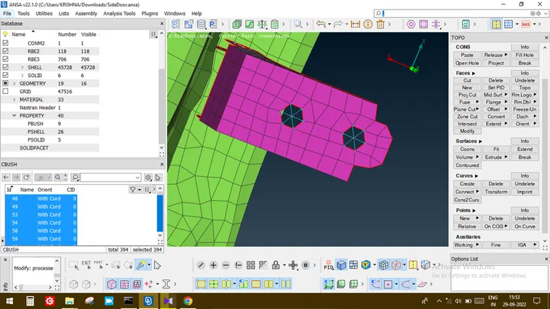
- In CBUSH column- by using shift+? Key, a PID tab will be opened. In that, a new CBUSH PID should be created and selected.
8. Then Click APPLY and Realize option to create CBUSH.
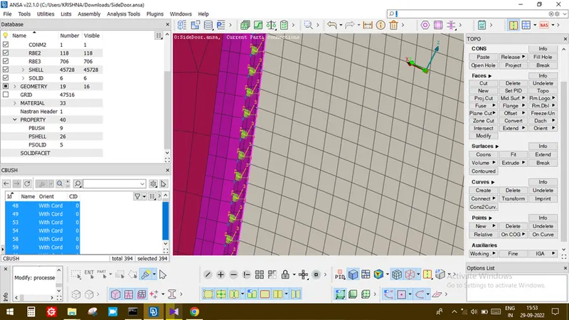
- The same procedure is repeated at different locations to create the CBUSH.
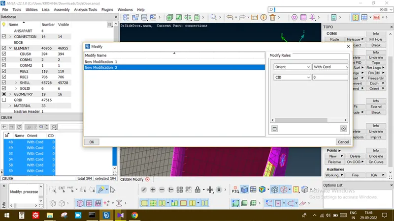
- Since the created CBUSH is having individual coordinate system,We need to make each CBUSH coordinate system similar to the global coordinate system.
- For that , Selecting CBUSH property, in that right side edit option will be there, in that we need to select ORIENT and CID option.
- Then ORIENT should be kept as WITH CORD and CID should be kept as 0. By clicking OK the CBUSH coordinate system will be changed.
STEP 4:
CONNECTIONS IN DOOR HANDLE
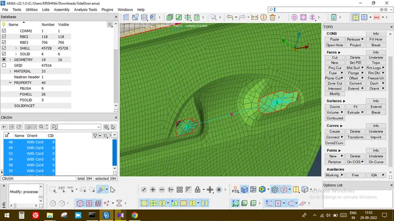
- Using NASTRON DECK – ELEMENTS – RBE2 – MANY NODE and enabling LOOP option the required nodes to be choosed
- On confirmation, slave node is chosen then master node will be created and it is stored in a separate ANSA part.
- In handle part,the nearby 2 master nodes are then selected under RBE2 option and assigned handle connection.
- Assigning CON mass to handle connection, it is done by selecting NAS DECK – ELEMENTS – CONMI – CONM2 – NODE and the proper node is selected to assign mass.
- A tab will be opened and in that, mass value of the handle should be entered in ton.
STEP 5: SPOT WELD CONNECTIONS
- Firstly, need to find the location of spot weld.
- Isolating the spot weld part separately.
- Using TOPO – POINTS – COG option, a COG point to be created at desired location.
- Converting the point to spot weld by using CONVERT – 3D POINT – SELECTING THE POINT - OK from the Top panel.
- Using connection manager, selecting the spot weld point and selecting P1 and P2 using F1key.
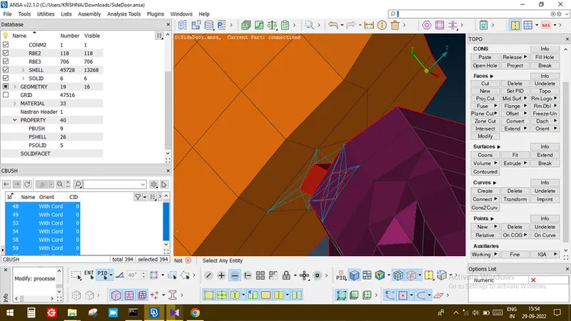
- In the FE REP TYPE select RBE-HEXA-RBE3, SEARCH DISTANCE – desired value, RBE3 PINFLAGE as 123456, In PSOLID – press shift+? Key and assign a new solid – ok.
- Clicking apply and REALIZE, the spot weld will be realized in FE.
STEP 6:
RIGID CONNECTIONS AND CLUSTER CONNECTIONS
- In FE, wherever rigid fixing components are present, there we will be using rigid connections.
- For creating rigid connections, selections NAS DECK – ELEMENTS – RBE2 – MANY NODE and enabling LOOP option the desired nodes are choosed.
- Thus slave node and master node are created and stored in ANSA part.
LEARNING OUTCOMES:
By doing this challenge, I came to understand various connection methodologies in door component.
CONCLUSION:
Thus for the given cad model, required connections operations are performed.