Week 6 - Creating connection for Rear door
#15 - Week 6 - Creating connection for Rear door
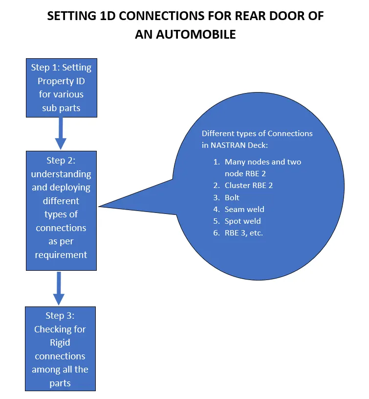
AIM: To perform different types of 1D connections to the Rear door FE model in order to set it right for further solving.
OBJECTIVE:
for the given Rear door FE model,
- Create and apply different PIDs for different components.
- Perform suitable connections.
[Note: All the connections are to be done in NASTRAN Deck as the solving will occur for Noise, vibration, and harshness (NVH) calculations.]
PROCEDURE:
After import Cad model to ANSA….
STEP 1: Setting PID ->
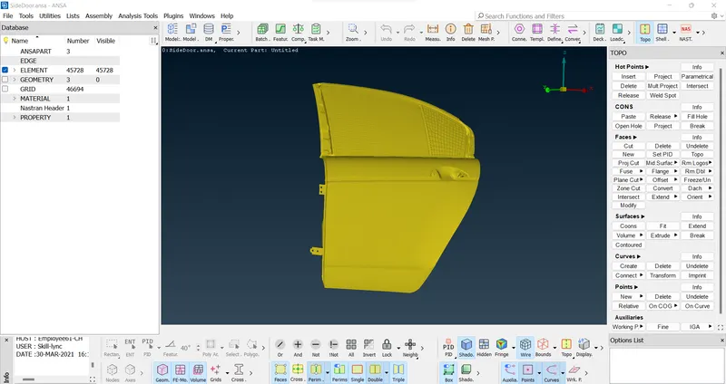
- Sub-part assembly before PID set for all the different parts. >>
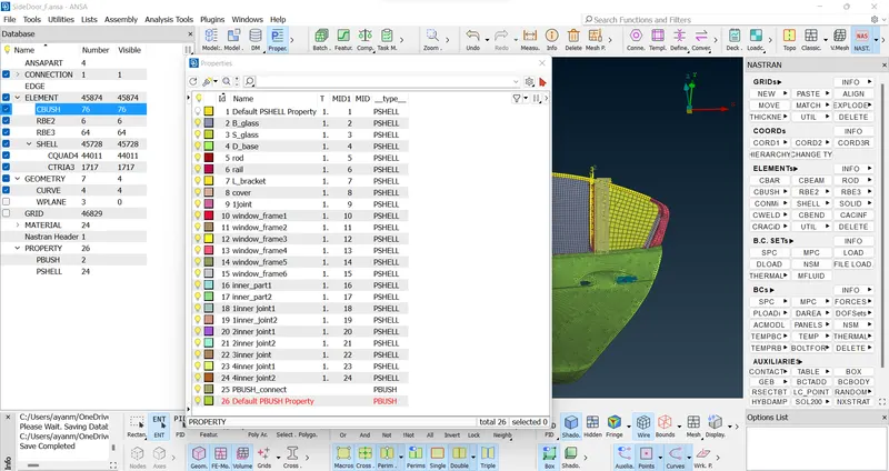
- PID set for all the different parts of the sub-assembly. >>
STEP 2: Deploying Connections ->
Typical steps followed while deploying connections >>
- Understanding the connection requirement with the help of available CAD data or element data.
- Realizing the connections with steps likes,
- Converting points or curves to bolts, seam or spot weld connection points.
- Realising FE models of connections after selecting proper FE representation type.
- Setting direct RBE2 connection when required.
//1 MANY NODES AND TWO-NODE RBE2's ELEMENTS
- They are the building blocks of connections that are used to rigidize parts. These elements can be optimized on the levels of nodes, physical connections, degree of freedom arrested, etc. These elements connect slave nodes with one master node. An example of a basic many-node RBE2 is shown below.(selecting the all slave nodes.)
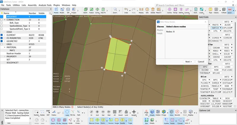
- / NASTRAN > ELEMENTs > RBE2 > selecting slave nodes > middle mouse click (master node created) > next .
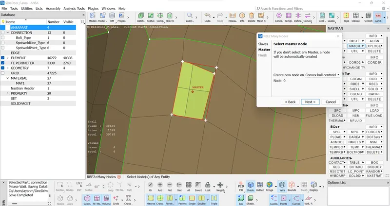
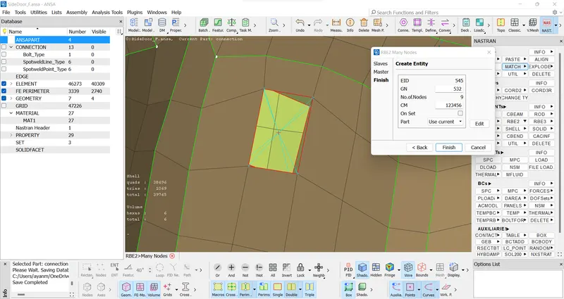
- Many Nodes cluster RBE2 element connection is created. In entity details "CM with 123456" explains that all the degrees of freedom (3 translations and 3 rotations along XYZ Direction) are arrested to rigidize the parts. It can be later modified if we allow motion in any direction or directions
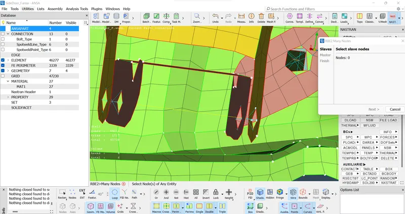
- Similarly, Two-Node RBE2 can also be deployed. Majorly it is used when parts are too big so two-node RBE2s can be deployed in all corners to rigidize two components or when the connection is to be performed where entities are large. Both the cases used.To connect the outer door panel with another long part, two-node RBE2s are used on all four corners.
- Number of RBE2s are created by joining four master nodes of the many node RBE2s. ( 2-node RBE2 is formed by joining Master nodes of the many nodes RBE2.)
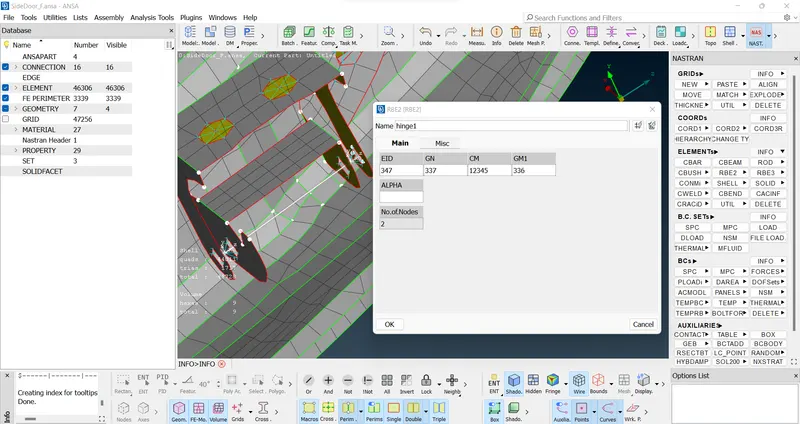
- And for both, in RBE2- two nodes we save a proper Degree of Freedom by removing 6 in CM(along with Z axis),
// 2 Bolt ->>
Major steps include point realization, entity conversion to bolt, connection realization.
- Make… On COG > convert 3D points as bolt > go to connection Manager > apply > realize.
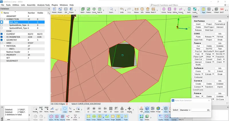
- Point is realized on a common part to be connected by a bolt. (creating COG point) >
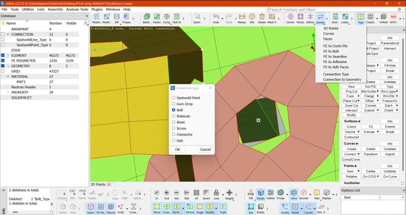
- Point is converted to Bolt. >
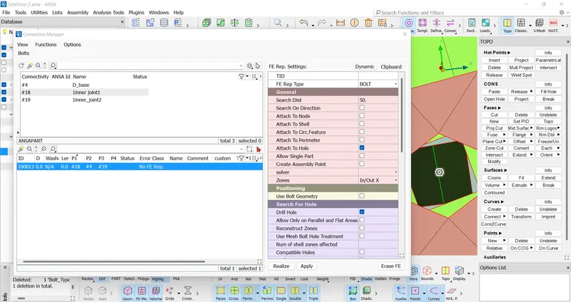
- PID's are connected using Bolt connection. While making bolt connection maximum of 4 parts can be connected with options use like search distance and zones etc. A cluster or spider representation can be seen as a Bolt connection. The connection can also be confirmed by seeing FE Rep type as "BOLT" and Body as RBE2.
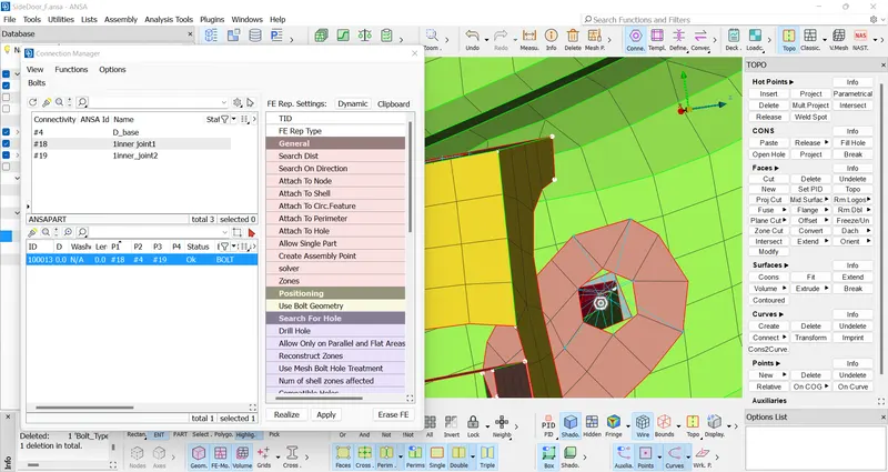
- Bolt connection can also be represented. >
- IN/OUT X Zone type representation is used for Bolt connection here Yellow strand represent bolt shank.
// 3 SPOT WELD ->>
Spot weld is realized where parts are close to each other, points are converted to spot weld connections with allowing parts to connect, FE REP is used as RBE3-HEXA-RBE3 and PSOLID ID is used for SPOT weld body.
- > Point is converted to SPOT Weld point.
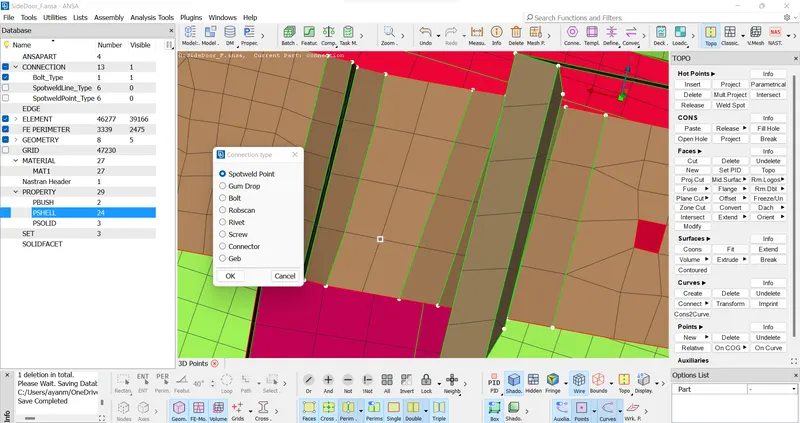
- In the figure above, structure element 2 and Sliding Glass guide are connected using Spot weld and FE rep type as RBE3-HEXA-RBE3. Later solid Id will be made for the Hexa element which will complete the Spot weld connection.
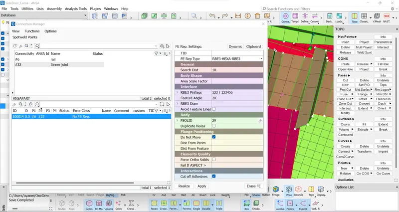
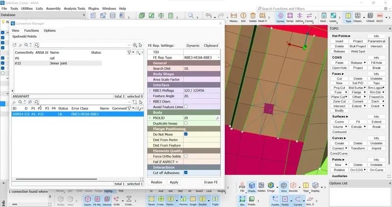
- Spot weld is realized between Structure element 2 and Sliding glass guide. (NOTE: Before realize In FE setting module body > PSOLID ID > shift + / for creating ID)
// 4 CONCENTRATED MASS ELEMENTS ->>
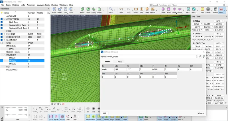
> In Door handle 2 RBE2 in two side > now again connect those 2 master node with a many node RBE2 and put mass on this master node using NASTRAN > ELEMENTs > CONMi > CONM2 > in M slot put proper mass in Tonne.
- In many places in an automobile door assembly, for accessories like side mirrors, handlebars, etc. slots are provided for assembly. In such known cases, slots are connected with many Nodes RBE2s and a concentrated point mass is allocated on the COG of the elements replacing the original unavailable components.
- Concentration mass of .0001 US Tonne or 100 gm is given to Concentration handle mass
// 5 CBUSH CONNECTIONS ->>
In an automobile door assembly, connections with respect to Glass are crucial. In practical application glass in a door assembly moves downward but while doing connections for NVH solving they need to be rigidized. So, glasses are connected using CBUSH elements as they hold the property like stiffness and damping coefficient, etc. They are connected with weatherproofing strips.
- Typical steps include conversion of glass periphery into curves, curves conversion to spot lines, realizing connections between parts with FE Rep style as RBE3-CBUSH-RBE3, and PBUSH ID is also created.
- Perimeter of the mirror is converted to a curve using "FEAT2CURVE" & also use “cons2curve” options.

- Individual curves are converted to Spot Line. (Lower curve is copy by Transform option for both side attachment.)
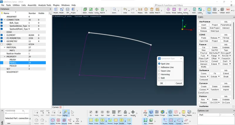
- Individual sliding glass and outside door panel is connected using Connection Manager > RBE3-CBUSH-RBE3 as FE Rep style and a new PBUSH ID is created with stiffness value input (in this case S =10).
- And also, we use NASTRAN > CBUSH > CURVE BOX > SPECIFY ELEMENT LENGTH.
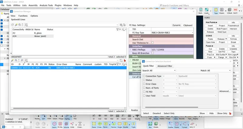
- CBUSH is realized between Sliding glass and outside/inside door panel.
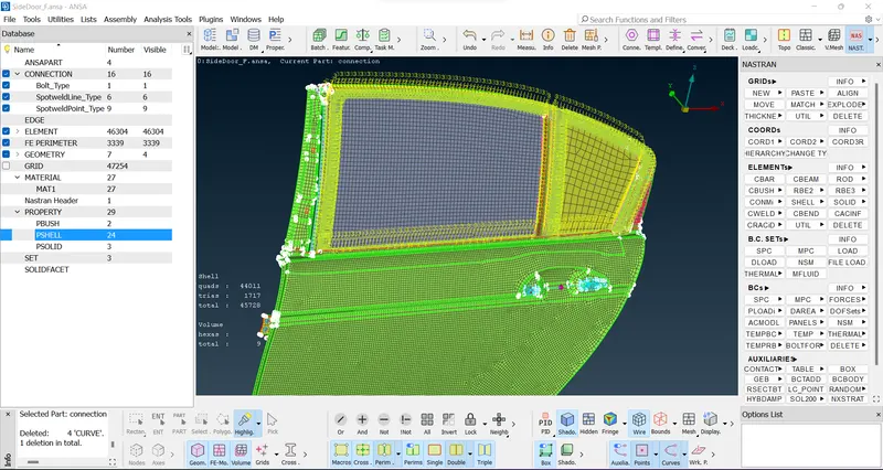
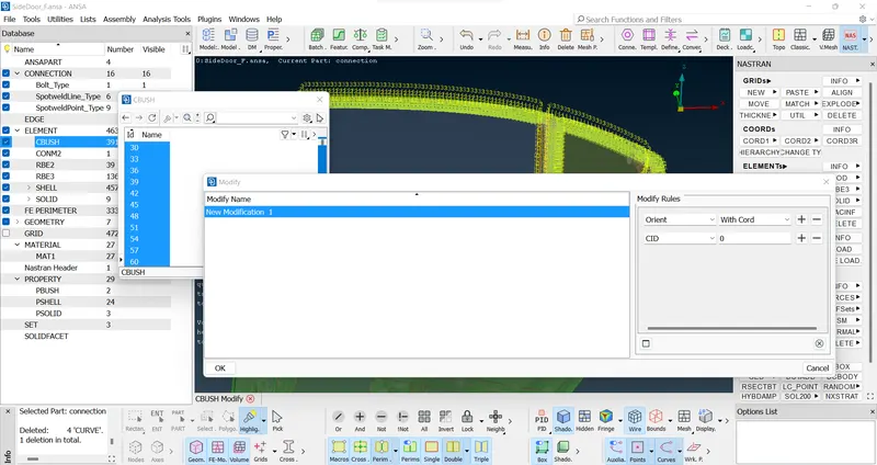
- After the glasses are fixed, the orientation of RBE3s is changed to global coordinates.
- >> Coordinate ID is set to zero.
Using the connections discussed above rest of the Automotive door assembly is connected to each other. Making the model complete for further NVH solving.
Learning Outcomes:
In this challenge I learned how to create connections for an FE model. The connection types such as RBE2-Two and many nodes, RBE3-CBUSH-RBE3- CBUSH, RBE3-HEXA-RBE3 - Spot weld.
CONCLUSIONs:
- While preparing any assembly for FEA analysis, physical connections must be provided to represent the actual conditions.
- Connection types include seam welds, spot welds using elements like ConMass, RBE2s, RBE3s, CBUSH, etc.
- ANSA offers various connections depending upon the deck types.
- ANSA provides easy access to review and access all the element types.
FINAL MODEL LINK:
https://drive.google.com/file/d/1Ia7AYEmXMXvsxMYTHYa2kTG265H9SUO6/view?usp=sharing