Week 6 - Creating connection for Rear door
CREATING VARIOUS CONNECTORS IN ANSA
OBJECTIVE:
To create and realize various types of connectors for the FEA model. Assign with proper properties to it.
INTRODUCTION:
Each and every model are an assembly of multiple components. These components make a connection between one to another, which brings to an assembly to function. Considering joint DOF and joint stiffness there are multiple joint options are available in industries. It may classify into permanent and temporary joints. These joints are done a huge role for a model to operate. So, it has to be considered for FEA analysis and simulations.
In spite there are plenty of joints are available, we hereby use some basic joints.
- Spot weld.
- Seam Weld.
- Bolt and nut.
- Bush.
- RBE2 and RBE 3.
PROCEDURE:
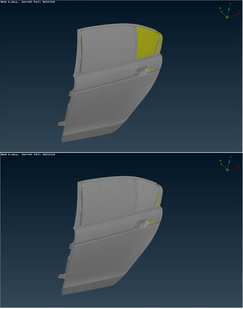
The geometry imported on ANSA and geometry cleanup have been done. Then model orientation has been updated according to the model. Each component on the model identified, separated, and set Property ID. In this process, each and every model gets a different property ID which allows easy access to the model.
Pic : Model
For different types of connections, there are different methods to create connectors,
RBE 2:
RBE 2 is a rigid joint that transfers displacement from node to node. It’s connected nodes.
- It basically spat into 2 types Many nodes and Two nodes.
- As the name refers Many node RBE2 elements connect many nodes for an FEA model and It has to be defined with a part ID.
- Two node RBE2 elements connect 2 nodes in an FEA model and defined with a part ID.
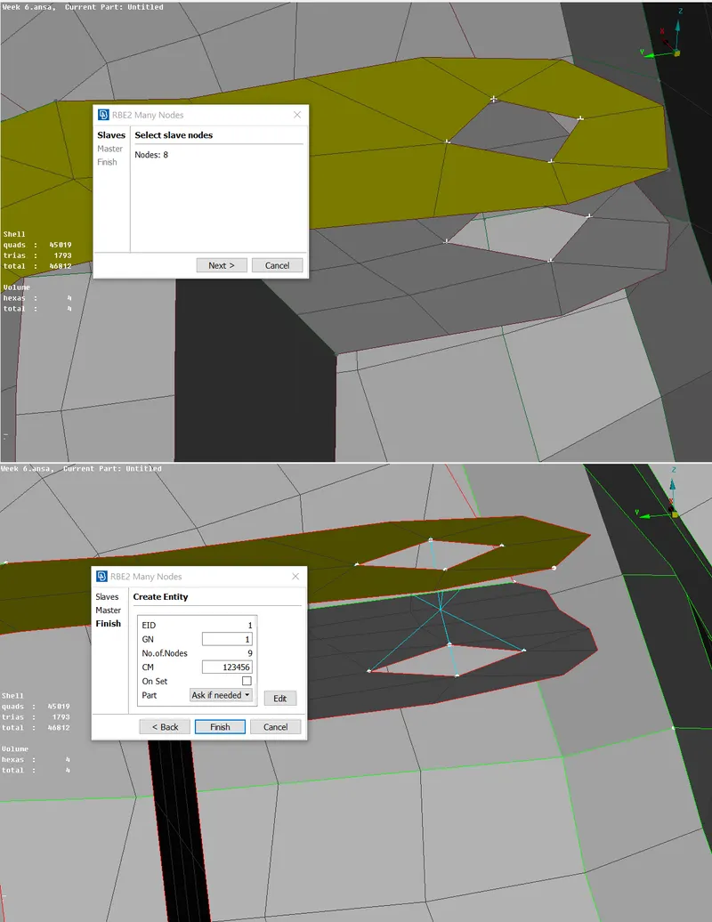
Cluster RBE2, when 2 holes nodes are connected to a single master node and provide rigid joints between 2 models.
Pic: Cluster RBE2
SPOT WELD:
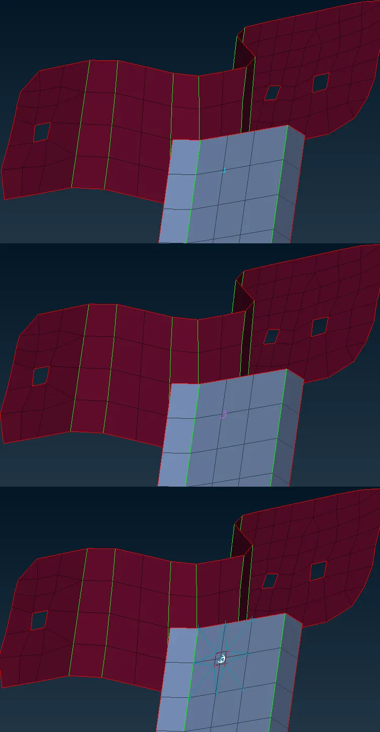
Spot weld is a fusion process of combining components that connects permanently with each other. This only connects to a point in a model. For FEA representation it has a joint for 1 element and creates jointly with other components FEA model.
- Initially, COG is created for elements that are going to be spot welded.
- These 3D points then convert into Spot weld by an option called
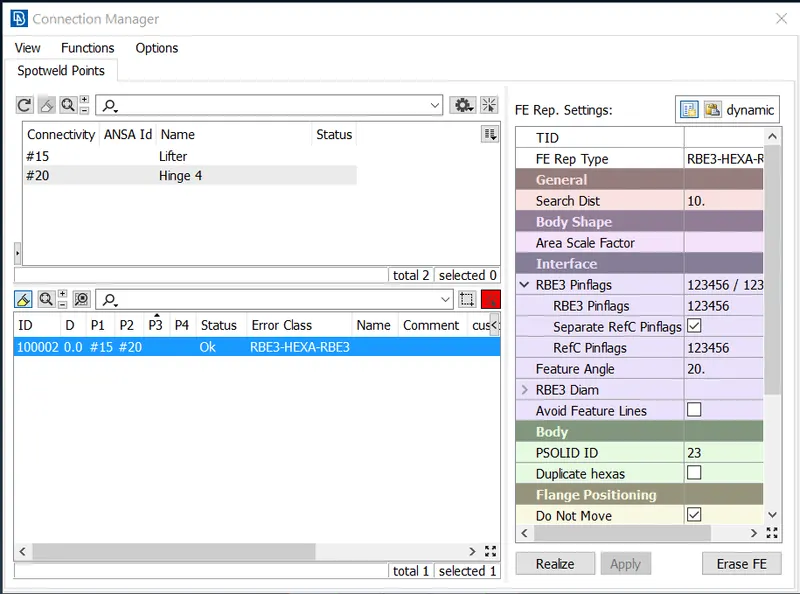
- This Spot weld then gets into connection manager, and plate 1 and other connection plates property ID are marked as P1, P2, etc.,
- For an FEA representation, RBE3-HEXA-RBE3 is selected.
- Search distance is provided with DOF (RBE3 pin flag) which arrests all 6 axes.
- Solid ID is created on the property tab with an ID entered into the connection manager.
- After that, it has realized the connection.
Pic: Spot weld
Pic: Connection manager Spot weld
SEAM WELD:
Seam weld is a permanent joint which connects 2 or more model for a distance.
- Create a line as long as the connection will be.
- This line then converted into a seam line.
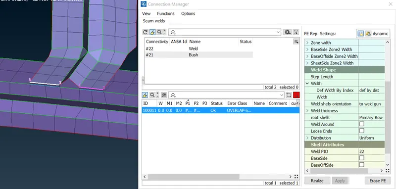
- Using connection manager, parts are entered and chosen OVERLAP SHELL for FEA representation.
- In case plates are perpendicular, then it will be in a Y-joint shell.
- The base sheet has given value according to model thickness.
- The width and root shell have been updated if required.
- Weld PID has entered, then model realized.
Pic: Seam Weld
BOLT:
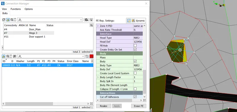
Bolt is a temporary joint, which will arrest all degrees of freedom.
- Create COG for the hole.
- Convert this point into bolt.
- After assigning properties connections are realized.
Pic: Bolt
MASS:
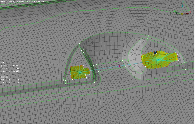
For every model which has joint within component’s have a considerable amount of mass. This mass is given as a point load in an FEA model.
Here, the door handle has been given with mass, Sides of holes are connected with RBE2 elements and those connections are then connected with 2 node RBE2 elements. CONMi defined mass to the nodes, in-unit of tonnes.
Pic: Mass
BUSH:
Bushes are the connections that connect components, with damping force.
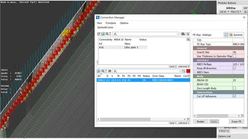
- Initially create lines where joints have to be heled.
- Converts this curve into the Spot weld line.
- For FEA representation RBE3-CBUSH-RBE3 is created.
- S value has been updated and P1 and other property have been defined.
- Particularly, the Keep all branches option is enabled.
- Then the model is realized and connections are made.
Pic: Bush
RESULT:
The given FEA model has been created with connectors and realized. Final model has been checked and uploaded.