Deploying the Connection for Rear Door in the Vehicle
Aim -
To deploy the connections to the rear door of the car in ANSA
Objective -
- To understant the differenet types of connection available in ANSA GUI.
- To deploy the connections for all the required locations in the rear door.
- To deploy the appropriate DOF for the door assembly.
Introduction to 1D Elements
Before moving to the connection part let us understand hte theory of 1D element liitle bit to perform the type of connection.
Wheneve there is requirement of deploying the connection in FEA the element type comes into any FEA modeller mind is 1D elements. We all know well that 1D elements is the one which have one dimension very large compared to the other two dimensions.
Element type available in 1D elements are : Rod, Beam, Bar, Pipe, Axi-Symmetric Shell, etc.
In practical following elements are commonly used:
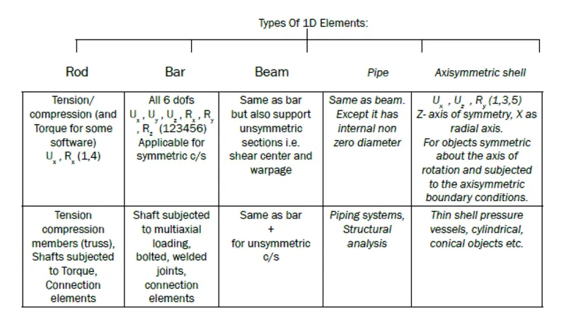
1D elements perform a critical function in Finite Element Analysis as they can be used to connect nodes together, attach dissimilar meshes, distribute loads and in general provide a quick and easy way to attach things together. There are numerous types of 1D elements ranging from infinitely rigid simple connections to complex cross sectioned elements that can be stressed.
The following is a list of the different element types and their purpose -
• Bar2: supports complex beams
• Bar3: supports complex beams (bar3 elements contain a third node designed to support second order beams)
• Gap: supports gap elements
• Joint: supports kinematic joint definitions supplied with safety analysis codes
• Plot: supports display type elements
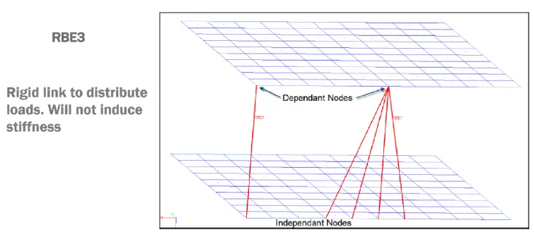
• RBE3: supports NASTRAN RBE3 elements
• Rigid link: supports rigid elements with multiple nodes
• Rigid: supports rigid elements
• Rod: supports simple beams
• Spring: supports springs or damper
• Weld: supports weld elements
Connectors - What Are They?
Connectors are a geometric representation of connections between entities. The advantage of connectors is the ability to create multiple connections at a single time.
The connector is simply a database of information defining a specific request for connection at a specific location.
A connector definition describes the connector between multiple entities at a specific location. Entities that are to be connected are referred to as link entities. The connector location can be defined as a node or node list, a geometric point, a line or line list, a surface, or even as elements or tags.
Different types of connection which is possible deploy can be seen in the below image:
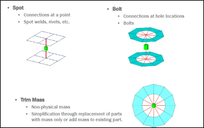
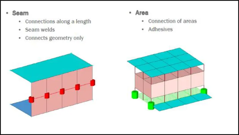
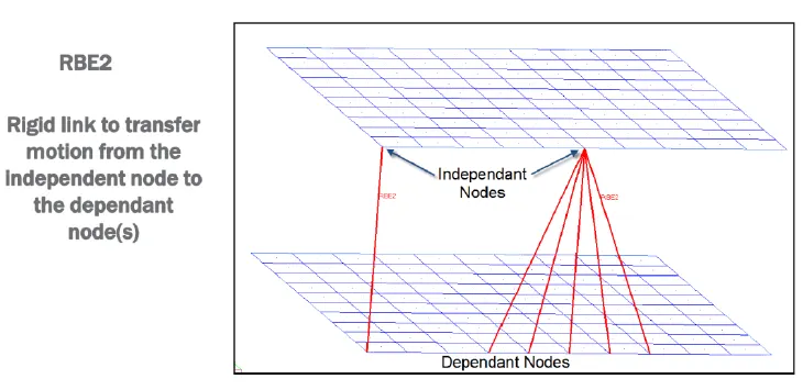
While definning any type of connection the modeller has to check all the below point to ensure the connection is well deployed and this are more like connection terminologies.
Connectors Terminology
• Link Entities - The entities that are being connected
• Connector Location - Where the entities are linked
• Connector Realization – The creation of the finite element representation of that connector
• Connector State – Whether an FE representation of a connector has been created
• Unrealized - The initial status of the connector entity upon creation
• Realized - The status only if creation of the FE weld representation at the connector was successful
• Failed – The status if creating the FE weld representation at the connector was not successful.
Car Rear Door Assembly:
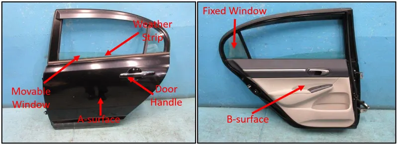
Doors of the car is one of the most important part in any automotive vehicle. The designer of the particular door model has to provide all the neighbouring door connections respected to sorrudding parts. Therefore it is very important for the Design and FEA modeller to define the correct connections in the door so that it will able to perform all it's operation smoothly.
The various operations which door is capable of performing are:
- Movement of the door along any one direction of rotation arond the hinge.
- Movement of the mirror in the door.
Procedure
#Import the FE Model
The user import the FE model of the rear side door in the ANSA GUI
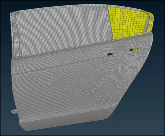
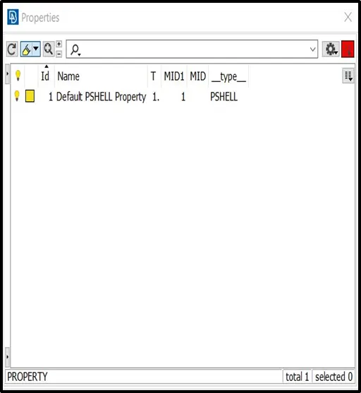
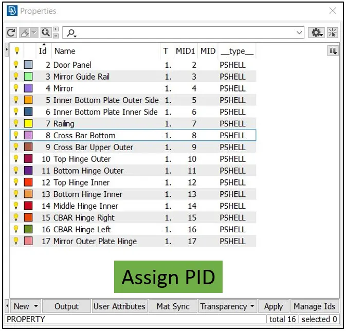
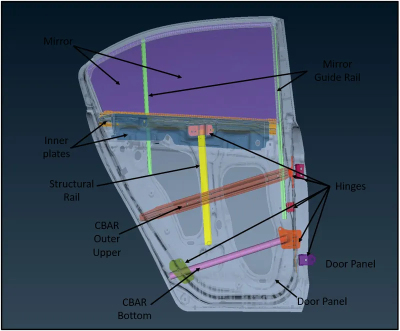
As we can see the impoted model in ANSA consist of single PID. The user first step is to segregate the similar group parts and assign the different PID to the similar group components.
#Assign the PID
#Connection Deployment
1. Bolt Connection between Door & Hinge
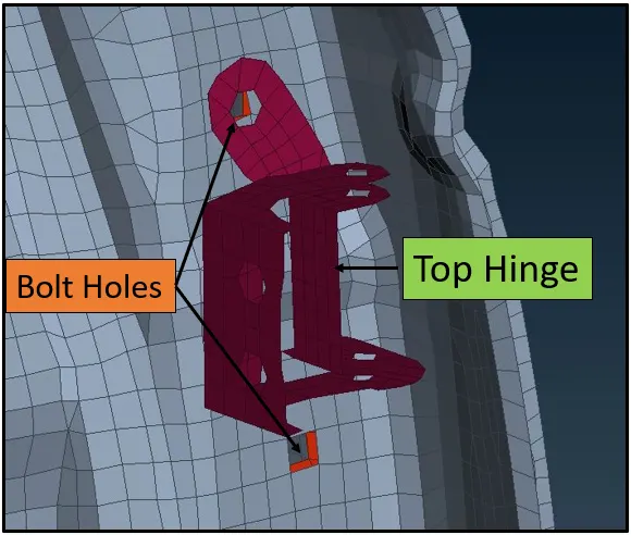
In the above image we can see that that there are two holes which is to be connected with the hinge to restrict the motion of the door to come out of the car. For this the user prefers the bolt connections as shown below.
To deploy the bolt connection in this location the user follows the below steps:
- Define ON COG point under the Topo Module
- Convert the point into 3D Point to to deploy the bolt connection
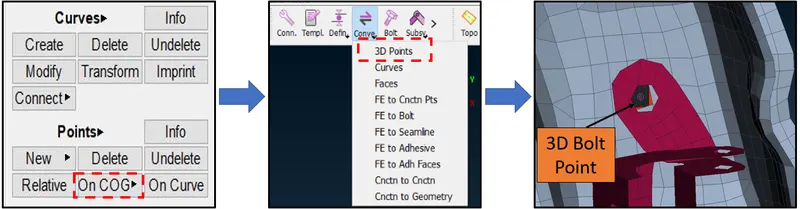
- Deploying connections using Connection Manager
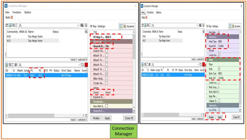
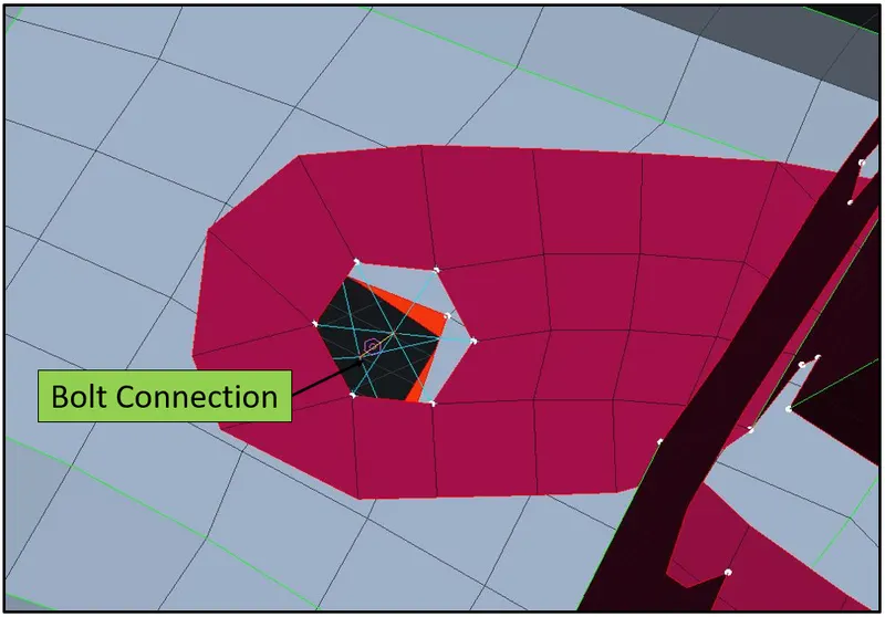
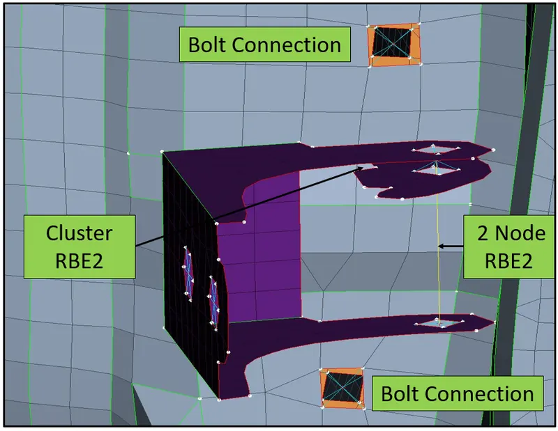
After deploying the connection between the door and the hinge the user dedine the connection fot the bolt holes in the hinge along which would restrict the movment of the door in the rotation Z-axis.
- Creating Cluster RBE2
- Defiing the 2 node RBE2 between two Cluster RBE2
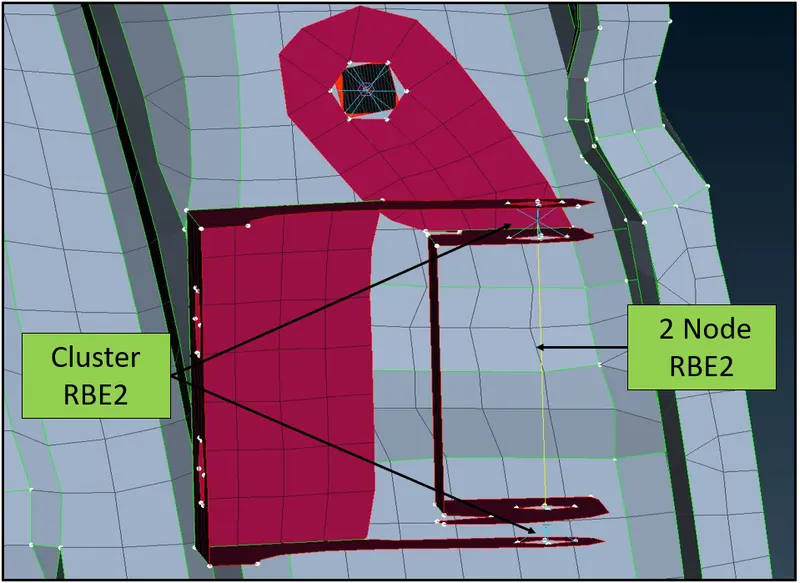
To restrict the movement of the door hinge the user change the DOF of the stem od the RBE2 (yellow color) to 12345 mean that the rotation about Z-axis is unlocked and the door will be able to rotate in the Z direction only.
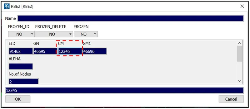
Similarly same process is follewed for the connection between door and the other hinge available in the model.
2. Open Hole Connection RBE2 Many Nodes
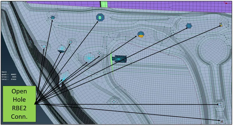
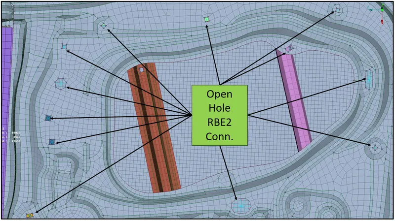
The open holes are the one for whiuch there should be data provided from the cad modeller to deploy the appropriate connection. As here the user don't have the sufficient data available for this FE model this holes need to be given atleast some type of connection. For easier and better deployment the user prefer to assign many node RBE2 connection to all the open holes present in the FE model.
Steps involved to deploy many node RBE2 Connection
- Switch to Nastran Module
- Select Element type as RBE (Rigid Body Element)
- Under RBE select Many node RBE2 Connection
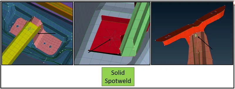
3. Deploying Solid Spotweld Connection
Some locations as shown below have no connection data available between them. To make connection between the two parts the user uses the solid spotweld connections.
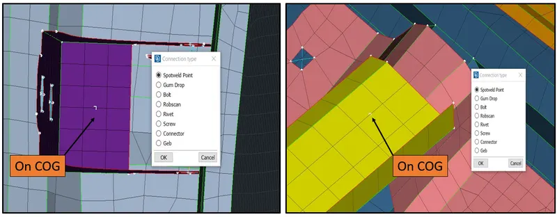
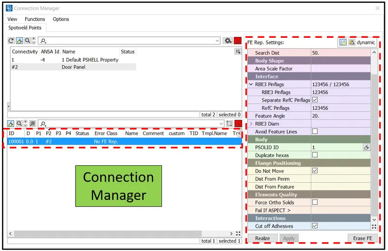
Step involved in Spotweld Connection
- Define the on COD point using the edges of the meshed macros.
- Convert the COG points into Spotweld points.
- Define the FE representation as spotweld using RBE3-HEXA-RBE3.
- Define the Search Distance.
- Define the DOF.
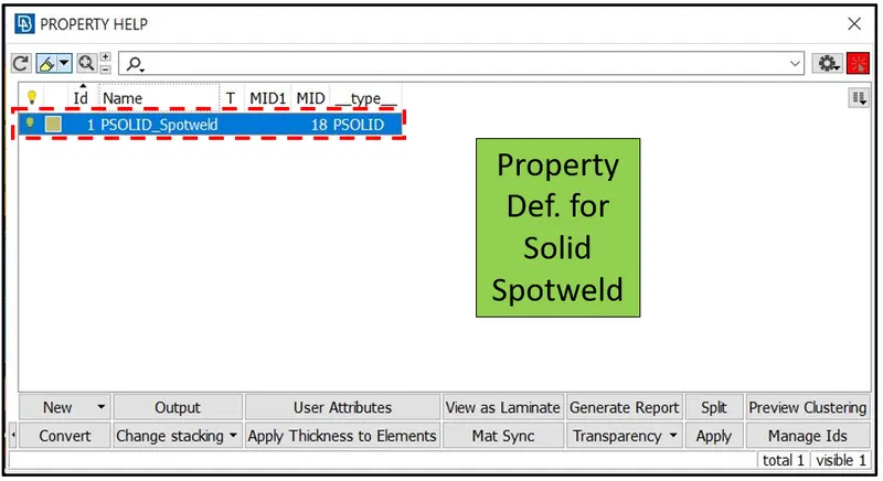
- Define the Soild Spotweld property PSOLID.
- Apply and Realize the Connection
All this step are shown below in picturised representation.
4. Deploying Connection for Door Handle
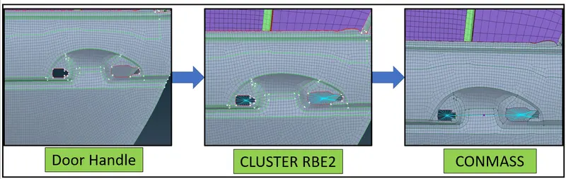
Door Handle is the place where there is concentrated mass is applied to find the strength of the door handle.
Step involved in Connection
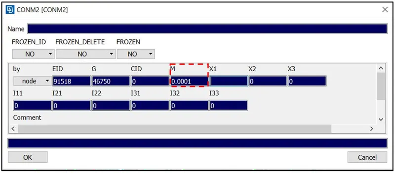
- Defiine the cluster node RBE2 connection across the nodes of the door handle using the RBE2 element in the Nastan Module.
- Add ConMass at the center of the Cluster and assign some mass value. As in ANSA the mass unit is considered in tonnes that is why the mass added is 0.0001 tonnes.
5. Weather Strip Connection for Mirror
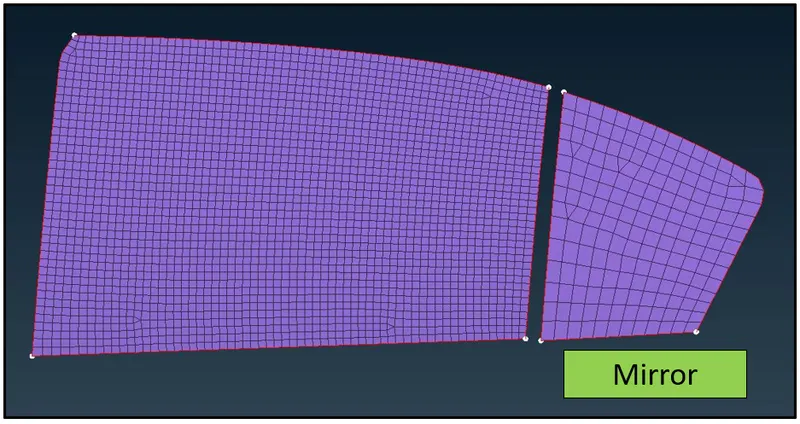
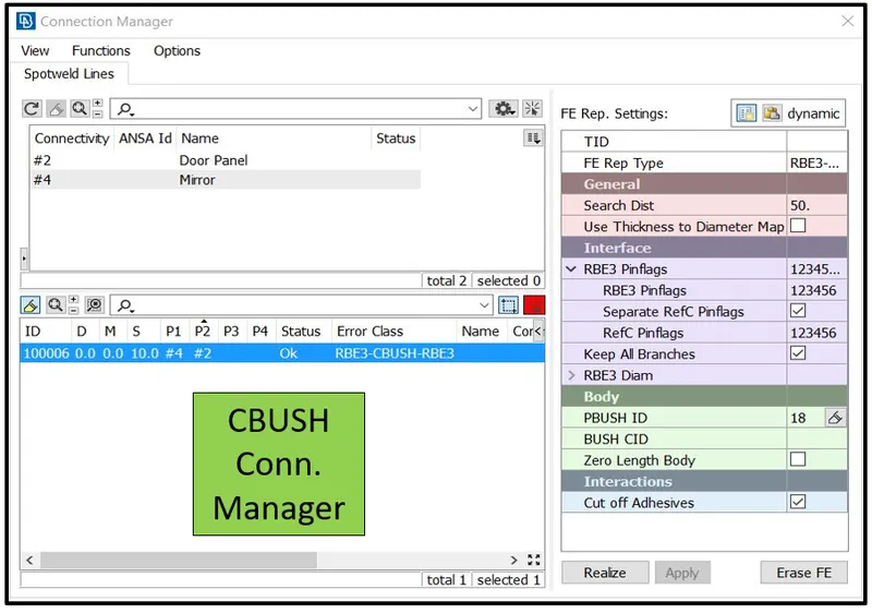
Weather strip connection is deployed near the mirror and the door panel. Weather strip connection is one of the important connection of all the connections. Weather strip help to maintain the climatic condition between the inside and outside air. To deplot the weather strip connection the user uses RBE3 - CBUSH - RBE3 FE representation.
Step involved in Spotweld Connection
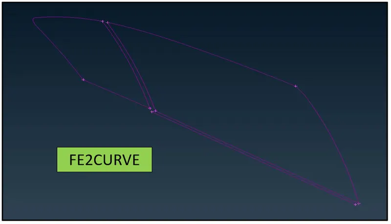
- Under the mesh module the user uses FE22CURVE option to extrac the curve of the FE.
- Trasnform the bottom curve to specific distance for representating the inside and outside weatherstrip connection in the bottom of the mirror.
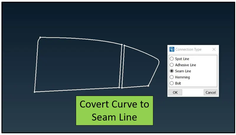
- Convert the curve into into Seam Line.
- Define the FE representation as spotweld using RBE3-CBUSH-RBE3 in connection manager.
- Define the Search Distance.
- Define the DOF.
- Define the property PBUSH ID.
- Apply and Realize the Connection
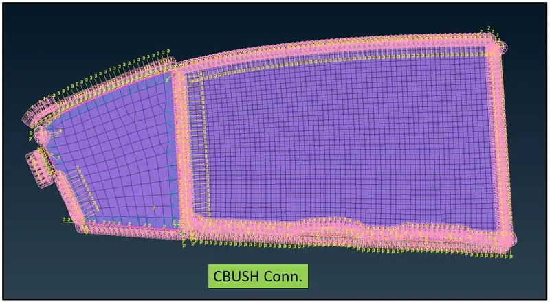
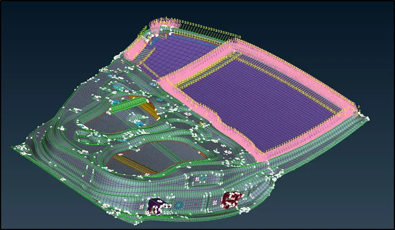
Complete Connection Model
Learning Outcome:
- Different types of connection in ANSA as well in FE
- Understanding the importance of the connection manager and convertion manager.
Conclusion
Performed connection for all the required location in the rear side door of the vehcile. Deployed most of the connection available in the ANSA user interface and understand the paramter involved while deploying the connections. Succesfully completed the project of connection in FEA using ANSA.