Powertrain Design for Taxing of Aircraft on Runway using HEV Model Design
AIM -
Designed a Power-train for Taxing of Aircraft on Runway using HEV Model Design
OBJECTIVE -
To develop a Powertrain for aircraft towing application to run on the runway using HEV [Hybrid Electric Vehicle] Concept and MATLAB
- To find the weight of various types of aircraft carriers.
- To study the difference between the ground and the airspeed.
- To study about the aircraft engine power.
- To study the movement of the aircraft on the runway.
- To study different terminologies related to aircraft.
- To calculate the force and power required to push/pull an aircraft by a towing vehicle.
- To design the powertrain with choice to select the type of motor required.
This all the objective are descrivbed in a detail manner in seven different studies.
Study - I - List of the total weight of various types of aircraft.
Maximum Take-Off Weight
The maximum take-off weight (MTOW) or maximum gross take-off weight (MGTOW) or maximum take-off mass (MTOM) of an aircraft is the maximum weight at which the pilot is allowed to attempt to take off, due to structural or other limits. The analogous term for rockets is gross lift-off mass or GLOW. MTOW is usually specified in units of kilograms or pounds.
Fig - Take Off Weight Components
MTOW is the heaviest weight at which the aircraft has been shown to meet all the airworthiness requirements applicable to it. The MTOW of an aircraft is fixed and does not vary with altitude, air temperature, or the length of the runway to be used for take-off or landing. A different weight, the "maximum permissible take-off weight" or "regulated take-off weight", varies according to flap setting, altitude, air temperature, length of the runway, and other factors. It is different from one take-off to the next, but can never be higher than the MTOW.
https://drive.google.com/file/d/1l4V0PxBoC_LQwLoauWl4af7qLDqM33p6/view?usp=sharing
--------------------------------------------------------------------------------------------------
Study II - Is there any difference between ground speed and airspeed?
If the aircraft is traveling relative to fix a point on the ground then the speed determined by the aircraft is ground speed. Ground speed is all about the movement of the aircraft across the land with respect to its own shadow. When the strong wind is pushing the aircraft that is reflected in the ground speed.
If the aircraft is flying under its own power subtracting the wind speed from the ground speed then the speed determined by the aircraft is the AirSpeed.
The Airspeed is normally equal to Ground speed but if the direction of wind or air is the same as that of aircraft then the Airspeed will be less than Ground speed.
--------------------------------------------------------------------------------------------------
Study III - Aircraft engine power is not used to move it on the ground at the airport
Although many aircraft are capable of moving themselves backward on the ground using reverse thrust (a procedure referred to as a power back), the resulting jet blast or prop wash might cause damage to the terminal building or equipment. Engines close to the ground may also blow sand and debris forward and then suck them into the engine, causing damage to the engine. A towing is therefore the preferred method to move the aircraft away from the gate.
fig - Aircraft towing by a truck
Jet blast is the phenomenon of rapid air movement produced by the jet engines of aircraft, particularly on or before take-off.
A large jet-engine aircraft can produce winds of up to 100 knots (190 km/h; 120 mph) as far away as 60 meters (200 ft) behind it at 40% maximum rated power. Jet blast can be a hazard to people or other unsecured objects behind the aircraft and is capable of flattening buildings and destroying vehicles.
Despite the power and potentially destructive nature of the jet blast, there are relatively few jet blast incidents. Due to the invisible nature of the jet blast and the aerodynamic properties of light aircraft, light aircraft moving about airports are particularly unsafe. Pilots of light aircraft frequently stay off to the side of the runway, rather than follow in the center, to negate the effect of the blast.
Towing with Taxibot saves precious fuel and reduces engine wear and tear. The ignition will be turned only when the aircraft reaches the runway. The usage of Taxibots will significantly bring down the consumption of fuel by as much as 85 percent used during taxiing of an aircraft. Taxi boats will also help in decongesting boarding gates and the apron area by providing efficient pushbacks.
So, to save fuel consumption and to take precautions against any damage on the airports due to jet blast it is recommended that aircraft should not use the engine power to move it on the ground at the airport.
--------------------------------------------------------------------------------------------------
Study IV - An Aircraft movement on the runway when it is ready to take off
In aviation, towing is an airport procedure during which an aircraft is pushed backward away from an airport gate by an external power. Towing is carried out by special, low-profile vehicles called pushback tractors or tugs.
Taxiing is the movement of an aircraft on the ground, under its own power, in contrast to towing or push-back where the aircraft is moved by a tug. The aircraft usually moves on wheels but is pulled or pushed back by a tug.
An airplane uses taxiways to taxi from one place in an airport to another like moving from a hangar to the runway. The term taxiing is not used for the accelerating run along a runway prior to take-off, or the decelerating run immediately after landing, which is called the take-off roll and landing rollout, respectively.
A taxiway is a path for aircraft at an airport connecting runways with the aprons, hangars, terminals, and other facilities.
Once the pushback is completed, the tow bar is disconnected, and any bypass pin removed. The ground handler will show the bypass pin to the pilots to make it clear that it has been removed. The pushback is then complete, and the aircraft can take off forward under its own power.
--------------------------------------------------------------------------------------------------
Study V - Study of various terminology of the aircraft
I] Take off power -
Take off power is determined as the power developed by the aircraft to take off (means to leave the ground and become airborne).
For aircraft that take off horizontally, this usually involves starting with a transition from moving along the ground on a runway.
For light aircraft, usually, full power is used during take-off. Large transport category (airliner) aircraft may use a reduced power for take-off, where less than full power is applied in order to prolong engine life, reduce maintenance costs and reduce noise emissions. In some emergency cases, the power used can then be increased to increase the aircraft's performance. Before take-off, the engines, particularly piston engines, are routinely run up at high power to check for engine-related problems. The aircraft is permitted to accelerate to rotation speed (often referred to as Vr). The term rotation is used because the aircraft pivots around the axis of its main landing gear while still on the ground, usually because of gentle manipulation of the flight controls to make or facilitate this change in aircraft attitude (once proper air displacement occurs under/over the wings, an aircraft will lift off on its own; controls are to ease that in).
II] Tyre design -
Aircraft tires may be tube-type or tubeless. They support the weight of the aircraft while it is on the ground and provide the necessary traction for braking and stopping. The tires also help absorb the shock of landing and cushion the roughness of takeoff, rollout, and taxi operations. Aircraft tires must be carefully maintained to perform as required. They accept a variety of static and dynamic stresses and must do so dependably in a wide range of operating conditions.
Aircraft tires are classified in various ways including by type, ply rating, whether they are tube-type or tubeless, and whether they are bias-ply tires or radials. Identifying a tire by its dimensions is also used.
Bias Ply Tire
fig - Bias Ply Tire
A bias-ply tire has the fabric bias oriented with and across the direction of rotation and the sidewall. Since fabric can stretch on the bias, the tire is flexible and can absorb loads. Strength is obtained by adding plies.
Radial Ply Tire
fig - Radial Ply Tire
A radial tire has the fiber strands of the ply fabric oriented with and at 90° to the direction of rotation and the tire sidewall. This restricts flexibility directionally and the flexibility of the sidewall while it strengthens the tire to carry heavy loads.
Tire Construction
It is useful to the understanding of tire construction to identify the various components of a tire and the functions contributed to the overall characteristics of a tire. Refer to Figure 6 for tire nomenclature used in this discussion.
III] Rolling resistance -
The force that resists the motion of a body rolling on a surface is called the rolling resistance.
Rolling resistance on the tire, in general, can be found out using the tire inflation and velocity of the tire or object for which we have to find the rolling resistance.
Rolling Resistance coefficient
The rolling coefficients for air-filled tires on dry roads can be estimated as,
Link for Formula -
https://docs.google.com/document/d/1ntZnca6BGPzNR4t5zLhNZqq_W49gZ2JmsI_zZn6l5mM/edit?usp=sharing
IV] Tyre pressure -
Aircraft tires generally operate at high pressures, up to 200 psi (14 bar; 1,400 kPa) for airliners, and even higher for business jets.
V] Brake Force on landing -
Very early aircraft have no brake system to slow and stop the aircraft while it is on the ground. Instead, they rely on slow speeds, soft airfield surfaces, and the friction developed by the tail skid to reduce speed during ground operation. Brake systems designed for aircraft became common after World War I as the speed and complexity of aircraft increased and the use of smooth, paved runway surfaces proliferated. All modern aircraft are equipped with brakes. Their proper functioning is relied upon for the safe operation of the aircraft on the ground. The brakes slow the aircraft and stop it in a reasonable amount of time. They hold the aircraft stationary during engine run-up and, in many cases, steer the aircraft during taxi. On most aircraft, each of the main wheels is equipped with a brake unit. The nose wheel or tail wheel does not have a brake.
In the typical brake system, mechanical and/or hydraulic linkages to the rudder pedals allow the pilot to control the brakes. Pushing on the top of the right rudder pedal activates the brake on the right main wheel(s) and pushing on the top of the left rudder pedal operates the brake on the left main wheel(s). The basic operation of brakes involves converting the kinetic energy of motion into heat energy through the creation of friction. A great amount of heat is developed and forces on the brake system components are demanding. Proper adjustment, inspection, and maintenance of the brakes are essential for effective operation.
Aircraft braking systems include:
- Aircraft disc brakes in the landing gear used to brake the wheels while touching the ground. These brakes are operated hydraulically or pneumatically. In most modern aircraft they are activated by the top section of the rudder pedals ("toe brakes"). In some older aircraft, the bottom section is used instead ("heel brakes"). Levers are used in a few aircraft. Most aircraft are capable of differential braking.
- Thrust reversers, allow thrust from the engines to be used to slow the aircraft.
- Air brakes, dedicated flight control surfaces that work by increasing drag.
The total braking force required can simply be calculated using Newton’s Second Law.
Bf=M⋅a⋅g
where,
B_f = Total Braking Force
M = Mass of the aircraft (Kg)
a = deceleration of the aircraft (g unit)
g = gravity (m/s^2)
--------------------------------------------------------------------------------------------------
Study VI - Calculating the force and power required to push/pull an aircraft by a towing vehicle.
The above study can be referred to using the below google document link.
Link -
https://docs.google.com/document/d/1ntZnca6BGPzNR4t5zLhNZqq_W49gZ2JmsI_zZn6l5mM/edit?usp=sharing
--------------------------------------------------------------------------------------------------
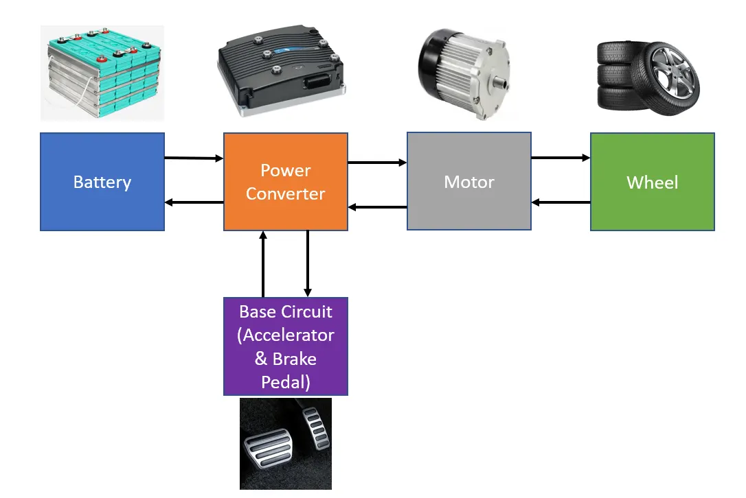
Study VII - Designing an electric powertrain with a type of motor, it’s power rating, and energy required to fulfill aircraft towing application. Estimation of the duty cycle range to control the aircraft speed from zero to highest. Making all required assumptions, preparation of a table of assumed parameters, and building the block diagram of the powertrain.
The above study can be referred to using the below google document link.
Link -
https://docs.google.com/document/d/1ntZnca6BGPzNR4t5zLhNZqq_W49gZ2JmsI_zZn6l5mM/edit?usp=sharing
Motor Selection for Powertrain
To select the motor is the prime importance. Based on the calculation done looking to the power requirement BLDC Motor can be used which can be operated using the DC battery source saving the cost compared to AC Induction Motor and also space as compare to AC Motors. The reason behind the selection of the motor is described below.
- A DC motor runs on anything that lies between 96 and 192 volts. In addition, more torque is generated from DC motors that lead to a cost-cutting aspect.
- DC motors are classified into three categories namely brushed DC motor, BLDC or brushless DC motor, and stepper. Brushed DC motors are widely used in electric vehicles for retracting, positioning, and extending electrically-powered side windows. These motors are suitable for many uses because of its low cost. However, the commutators and brushes tend to wear relatively quickly because of their continued contact, leading to periodic maintenance and frequent replacement.
- As the name implies, a BLDC motor doesn’t use brushes and employs an electronic commutator instead, which increases its efficiency and reliability by eliminating the source of power and wear loss. In addition, these motors boast of some significant advantages over induction motors and brush DC motors like higher speed ranges, noiseless operation, faster dynamic response, better speed versus torque characteristics, etc. Also, the ratio of torque delivered relative to the size of the motor is higher, which makes it a good choice for electric vehicles, where high power is required but lightness and compactness are critical factors as well. While BLDC motors are mechanically simple relatively, they do require regulated power supplies and sophisticated control electronics.
Block Diagram for Powertrain
Conclusion:
This project is successfully completed. Learning throughout the HEV concept is very useful and worthy. This project can help to work on the industrial project-based of HEV concepts. Further SIMULINK and MATLAB tool can also be utilized to make this project easier for visual representation.