CREATING A CONNECTION FOR FRONT DOOR
1. Objective:
Doing Connections for the front door by using different 1D elements. Create and Apply different PIDs for different components.
2. Procedure:
2.1 Importing Model: First We are importing the Door Model to Ansa.
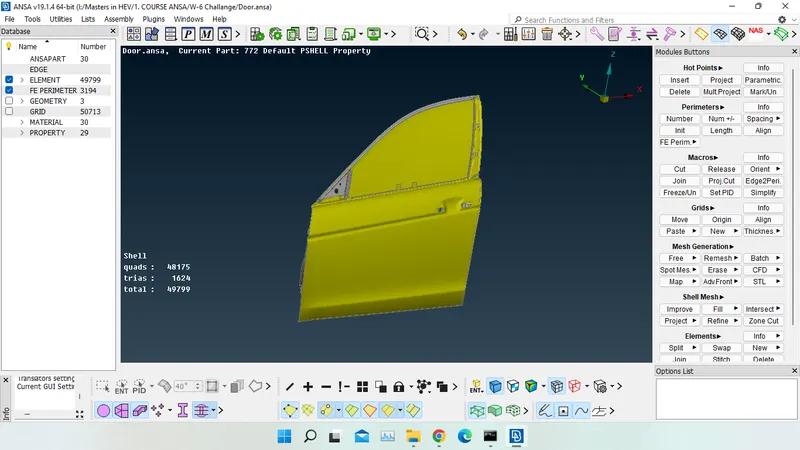
2.2 Connection of Door Hinge:
First, we are going to do a connection for the Door Hinge. We are going to make an automatic connection here. So, to do that we need to make a point in the middle of the circular hole. To do that go to the Topo section and select the On COG in the Points section.
Topo Module > Points > On COG
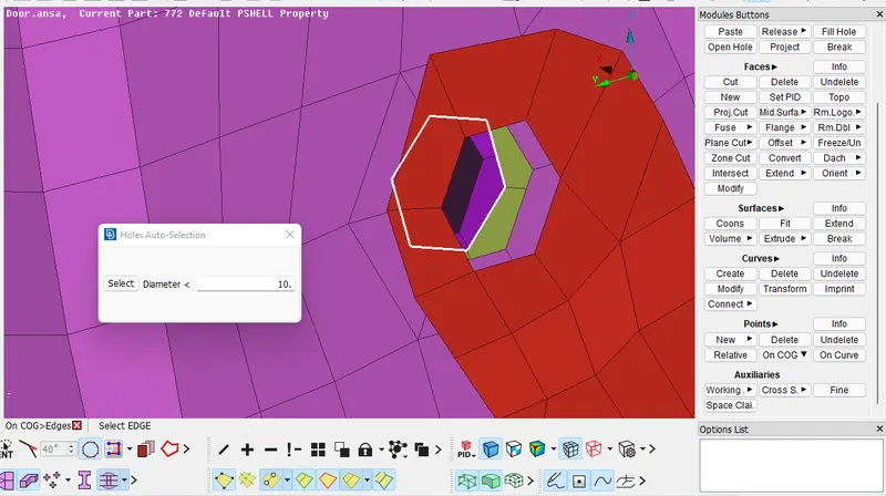
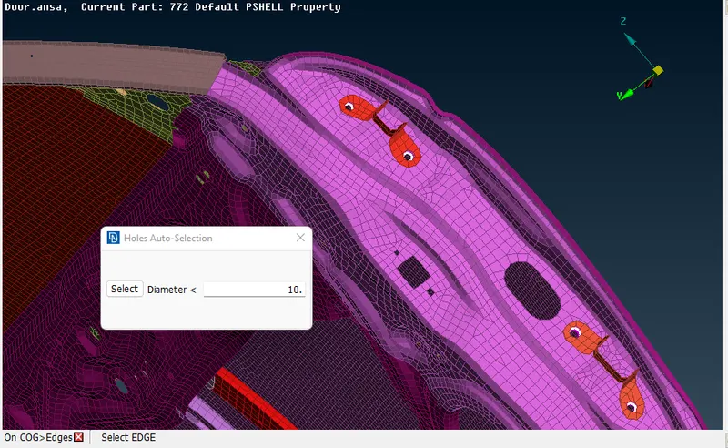
Now Select Loop as a selection Filter and Select any loop here. To Visualize it click on the points in the bottom right corner.
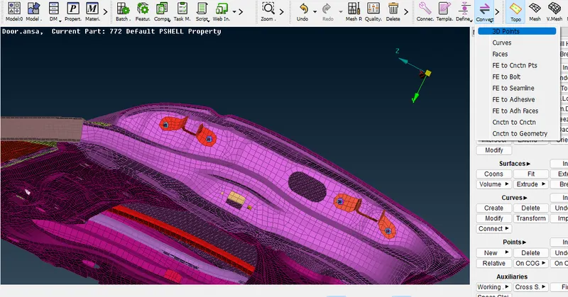
Convert Point to 3D Point and Set as a bolt.
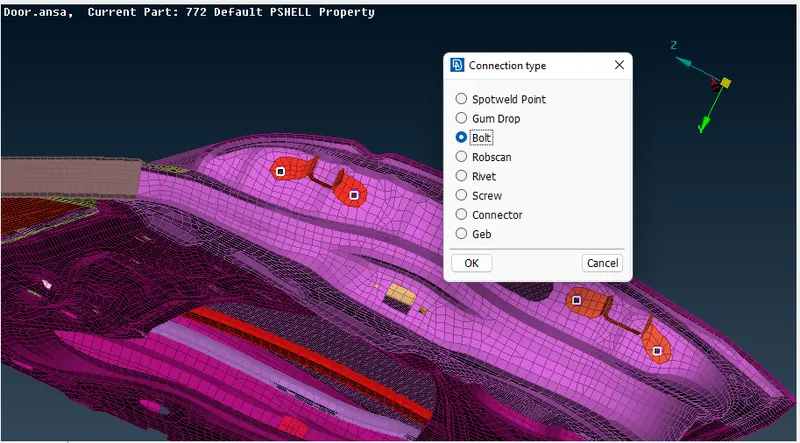
2.3 Setting Up PID:
Now we are going to realize the connection before we are going to define the new PIDs.
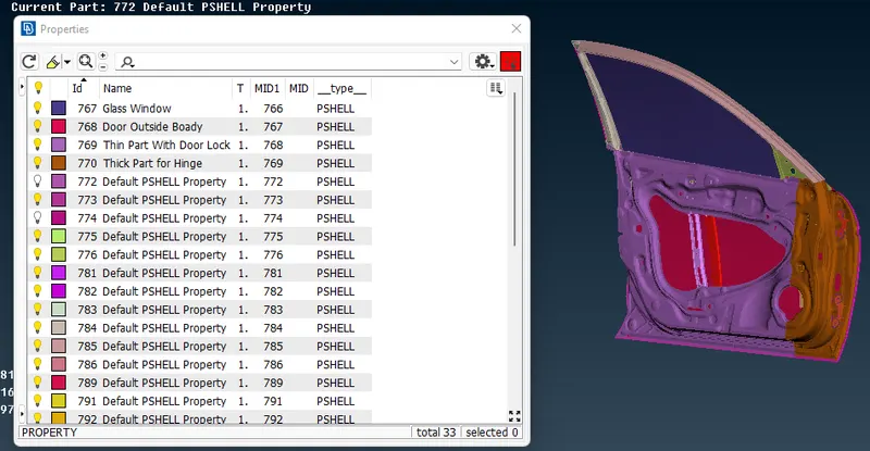
Creating and Applying different PIDs for different components. To-Do that goto Mesh Module > Macros > Set PID and Now Select the group parts and Define New PIDs as shown below.
2.4 Realizing the Bolt Connection:
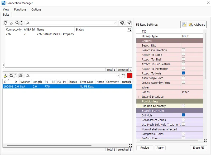
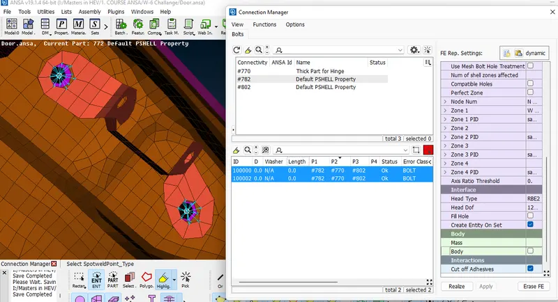
To do that go to the connection manager and select the one bolt now connection manager window is popup. Now select the FE Rep Type as a Bolt.
Modifying P1, P2, P3, etc.
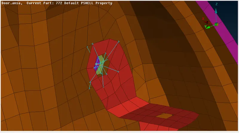
Right Click on P1 > Modify > Press F1 > select the first loop edge. Now again perform the same Step for P2, P3, and P4.
In any Connection, in Ansa FEA Modeling we do not have more than four Attaching Parts.
2.5 Door Hinge Mounting Part:
Now We are going to do a connection for Hinge Only with a Single Degree of Freedom.
To do that go to Nastran Deck and Select Many nodes > RBE2 in Elements and Select the Hinge hole nodes. Here We need to Select The Slave Nodes and the Master Node is Automatically Created in the center of the nodes.
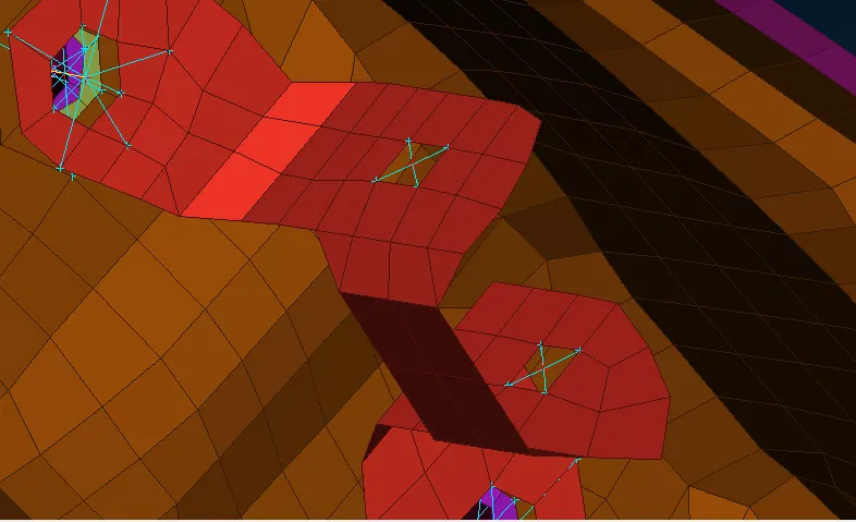
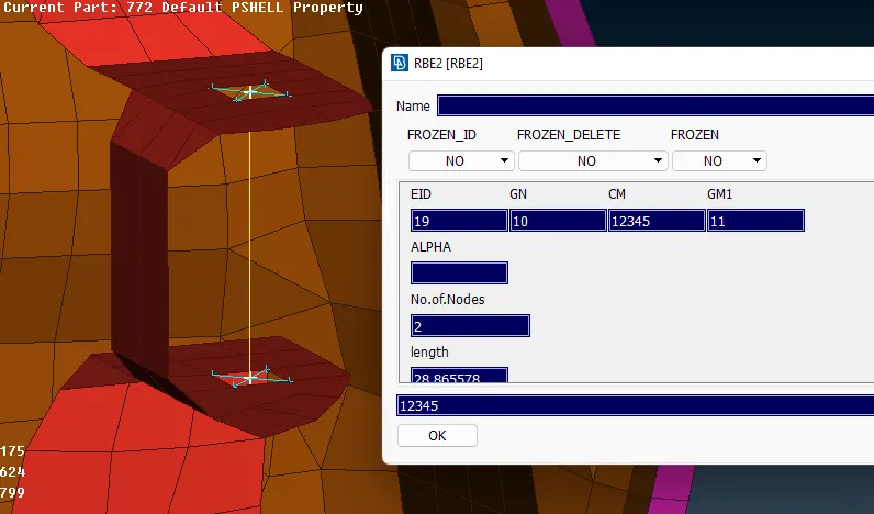
Now Joining Mounting Points in the Hinge Section for Defining the Degrees of Freedom Using 2 node RBE2.
Select 2 Nodes RBE2 in the Nastran Deck and Select the master Nodes after that its property is popups where we can see the 6 degrees of Freedom. To make the opening and closing of doors possible we need to remove the degree of freedom along the Global Z-Axis in our Case.
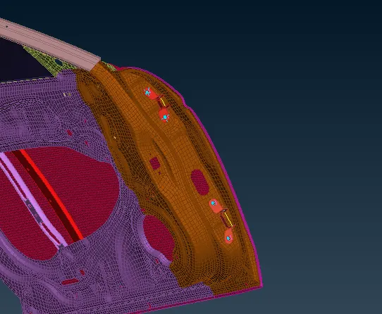
2.6 Defining Spot Weld:
Now in internal we have welded parts show to that first we need to make a point (using on Curve command in Points in Topo Module) > Convert 3D > Spot Weld
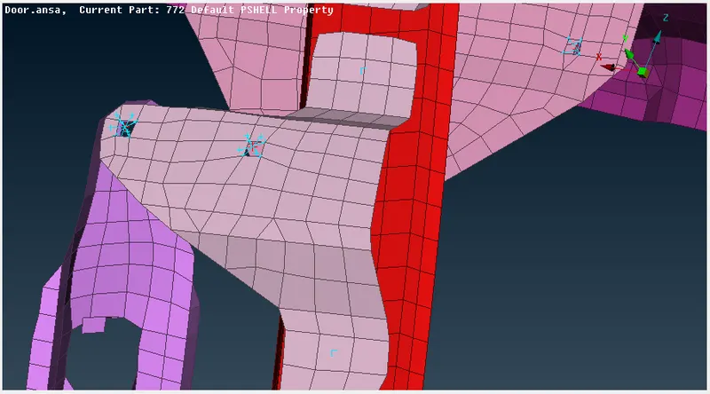
Connection Manager > Define P1 and P2 > Set Representation Type RBE3-Hexa_RBE3 > Create a solid ID in PSOILD ID (Press Shift + / key to open the property manager New > PSOLID then Press Enter)
Where:
Search Distance = 20
RBE3 Pinflages 123456
PSOLID ID is used to determine the material of SpotWeld Element.
Note: In RBE3 the Center Node is the Slave node and the surrounding Nodes are Master Nodes While in RBE2 the Center Nodes are Master Node and the Surrounding is Slave Node.
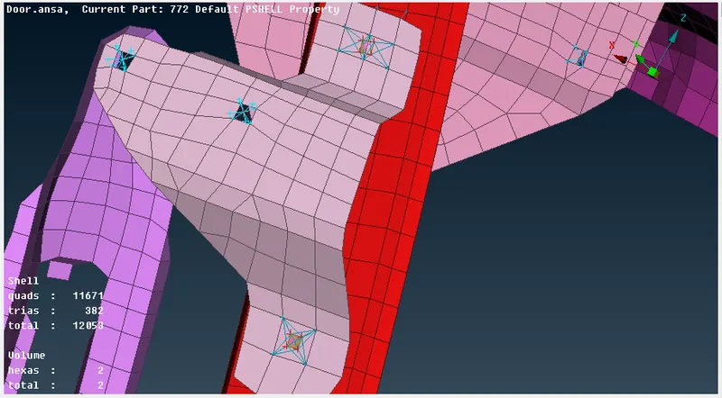
Now We are going to rest of the connections.
2.7 Slider With Glass Window:
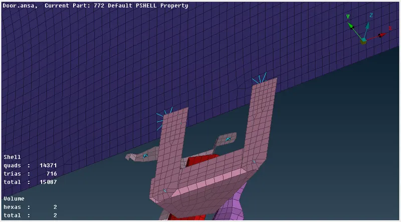
The Internal Slider Also Needs to Fix with the Body, So to do that Use RBE2 > Many Nodes > Use Entity Selection Filter to select the Elements and Deploy connection Here as shown below.
2.8 Door Handle:
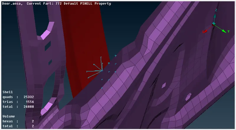
The Door Handle FEA Model is not present here but it will be having some significant importance in the simulation. Here we need to define an imaginary door handle with mass.
To do that first make the rigid connection between two mounting locations of the door handle and connect them after that we need to define its mass.
Command Used : Nastran Deck > RBE2 > Many Nodes > Use Loop option in Node > Select loop
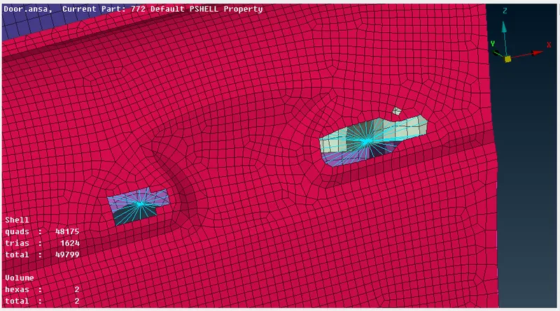
Now Connecting these RBE2 with RBE2 > Many Nodes
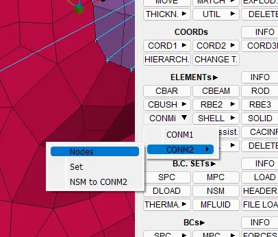
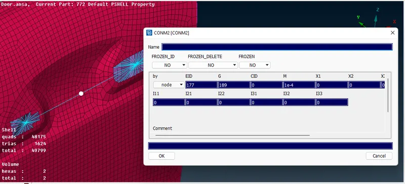
Now Defining Mass CONMi > CONM2 > Nodes and Define the Mass M as 1e-4
Where: M is Mass in Tonns
2.9 Modeling Door With Glass:
Goto Mesh Module > Feat2Curve > Use Feature line Selection Filter to select the line
Create a new line for the other side using Transform > Copy at a distance of 10 in the Y-direction.
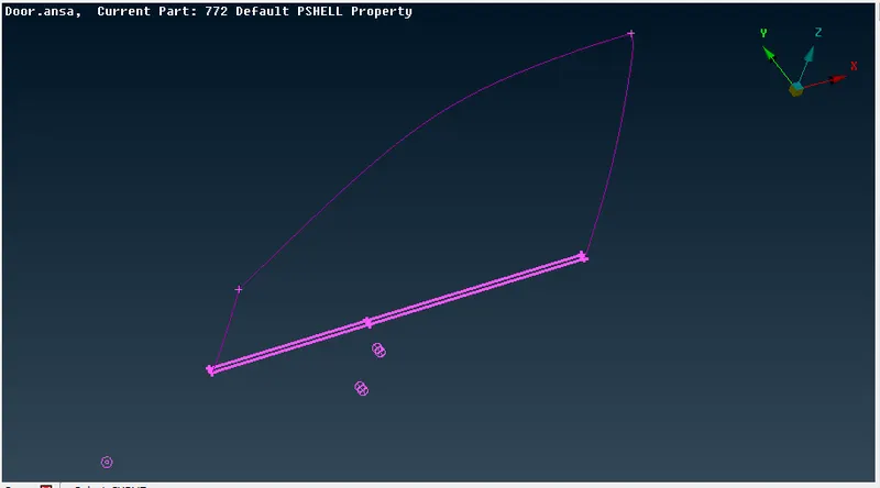
Convert > Curves > Spot Line
Note: Select Each Line one by one otherwise all the Curves will act as a single entity.
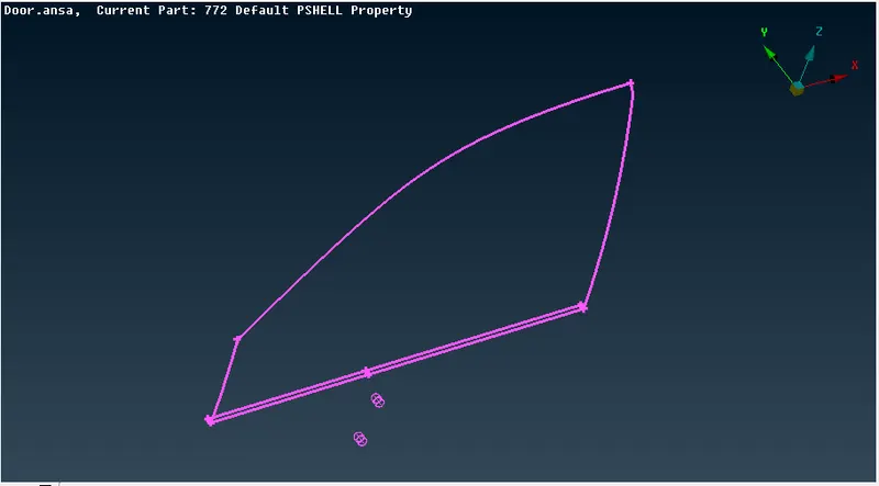
Connection Manager > First Select the Bottom only > Define S as 10 > Define P1 and P2 > Set FE Rep Type > RBE3-CBUSH-RBE3 > Search Distance 50 mm > define new PBUSH ID > apply values of K > apply > realise
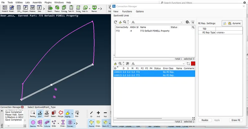
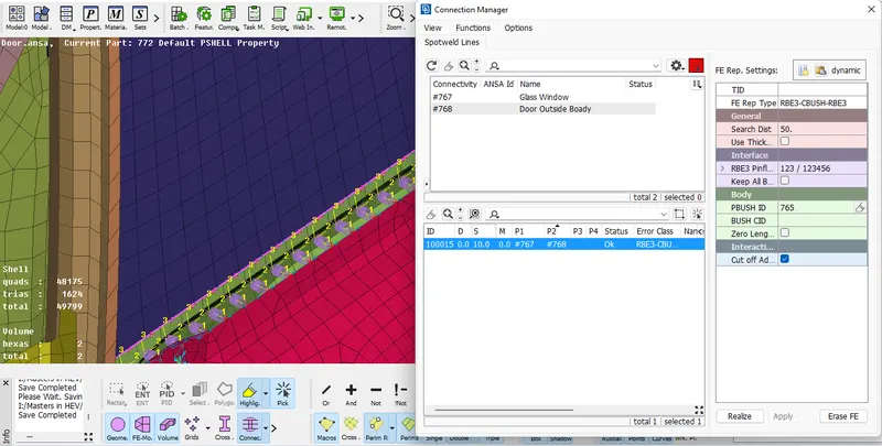
Note: PBUSH ID helps us to define stiffness values for other connections also. it Eliminates the value of K defining for each and every connection.
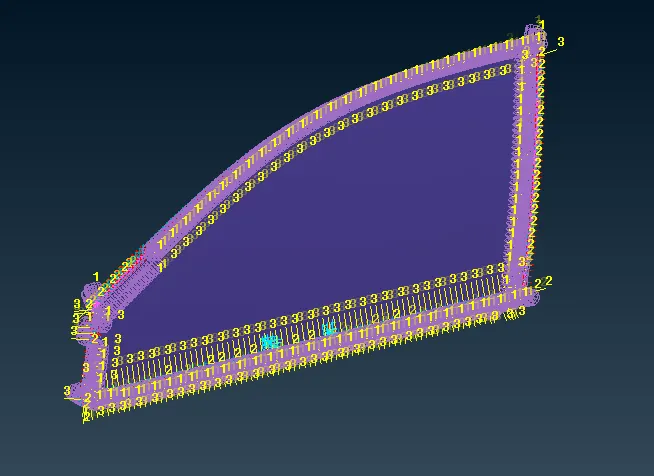
Now we can see that the connection is created here.
Similarly, we need to create a bush connection on the other side and all remaining areas of the Glass Window.
3. Conclusion:
We are able to perform a Connection of the door using the following Features.
i. Setting Up new PIDs.
ii. Realizing Bolt Connection.
iii. RBE2 Connection in Nastran Deck.
iv. RBE3 Connection in Nastran Deck.
v. Realizing Spot Weld Connection.
vi. Setting Up CBUSH.