MBD SIMULATION OF IC ENGINE VALVETRAIN.
1. Objective:-
1.1 To Obtain the:-
i. Valve Lift.
ii. The contact force between:-
a. Cam and Push Rod
b. Pushrod and Rocker Arm
c. Rocker Arm and Valve
Considered Simulation parameters:-
| SR. NO. | Cam Lift(mm) | Speed(RPM) | Material |
| 1. Case-1 | 3.5 | 1500 | Cast Carbon Steel |
| 2. Case-2 | 6 | 1500 | Cast Carbon Steel |
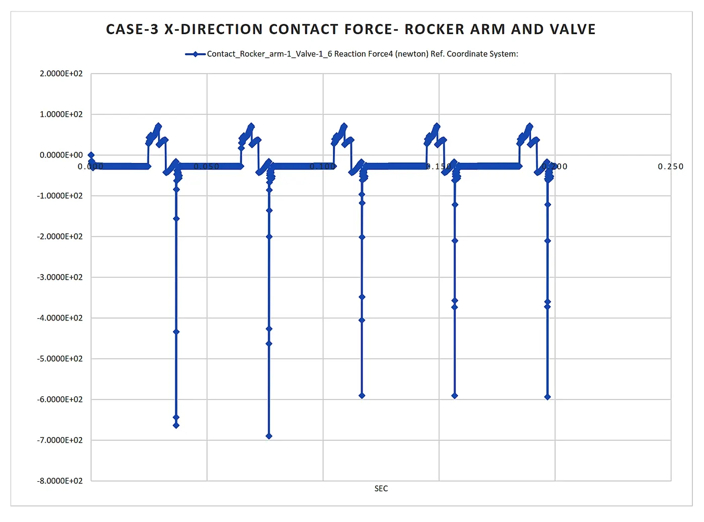
1.2 Contact force in X-direction (Case-3):- The contact force between the Rocker arm and valve concerning the X-direction and measuring with respect to magnitude.
2. Basic:-
The Valve train is a mechanical mechanism use to control the intake of fuel and exhaust of burned gases. It also avoids the backflow of exhaust gases and fluid which is injected in the combustion chamber. The train valve mechanism is also used in the external combustion engine, compressor, etc. In our consideration, we are taken a valve train mechanism for an internal combustion engine. the basic mechanism for an internal combustion engine is as shown below.
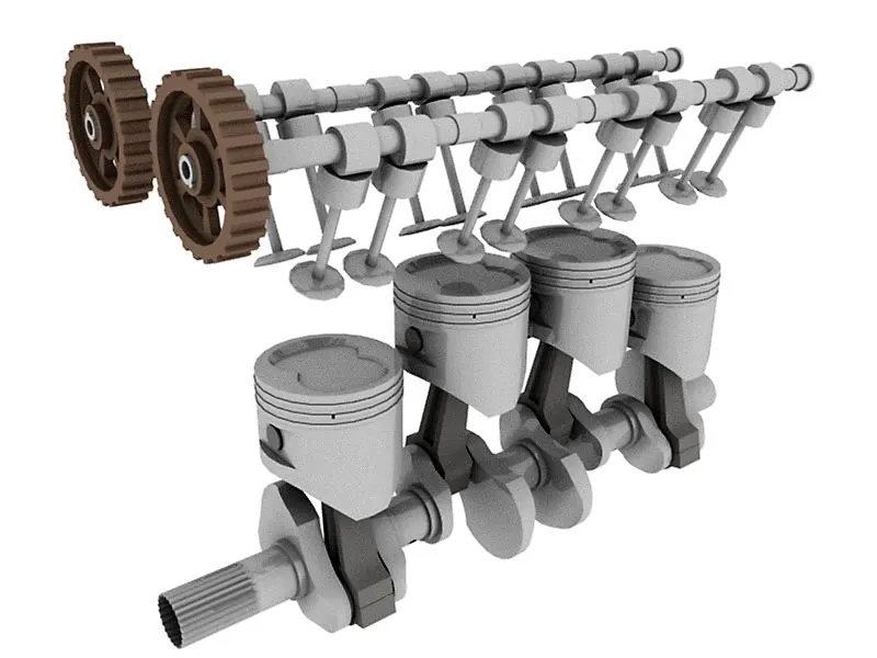
The mechanism is working with the help of timing Gears. The cam attached is used to maintain the opening and closing of the valve with respect to the movement of the piston in a cylinder.
3. Procedure:-
To do motion analysis of Internal combustion engine valve train assembly, we need to design its parts individually, after that we assemble them and use a motion analysis tool in SolidWorks to analyse different parameters related to it. The Approach used in the procedure indicated below in the table for better understanding of the flow of a report.
| Approach | Details |
| 3.1 Part Design | Procedure for Designing parts of Valve Train. |
| 3.2 Assembly | Assembling All the parts for simulation. |
| 3.3 Cam lift And Valve lift Calculation | Calculating the remaining parameters. |
3.1 Part Design:-
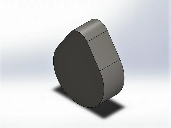
3.1.1 Cam: Cam is used to controlling the timing of the lift of the valve. Designing the cam with the help of a circle tool on the front plane with major circle diameter 25mm and minor circle diameter 10mm. extruding it to both sides of the plane by using the extrude option available in the features.
Note:- The center distance varies with the cam lift, therefore, we need to change the geometry of the cam according to the calculation which will be explained in the Simulation and Analysis section. Also, here we are not going to define all the dimensions used, we are just defining the approach to get these parts. Because the parameters can be different for the different mechanisms of internal combustion engine valve train and our objective is to determine the various parameter of the assembly.
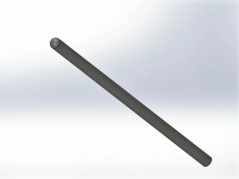
3.1.2 Push Rod: Pushrods are long, slender metal rods that are used in overhead valve engines to transfer motion from the camshaft (located in the engine block) to the valves (located in the cylinder head). The bottom end of a pushrod is fitted with a lifter, upon which the camshaft makes contact. The camshaft lobe moves the lifter upwards, which moves the pushrod. The top end of the lifter pushes on the rocker arm, which opens the valve. To get pushrod we sketch its dimension on the front plane and use revolve option available in the features.
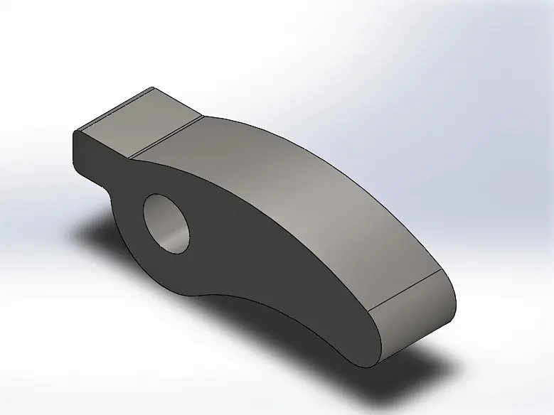
3.1.3 Rocker Arm: Depending on the design used, the valves are actuated by a rocker arm. which is actuated by a pushrod and pivot on a shaft or individual ball studs to actuate the valves. By sketching and extruding it to the desired dimension we can get rocker arm.
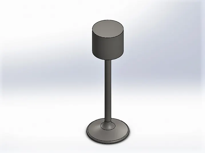
3.1.4 Valve: The valve is the part that handles the flow of fluid and exhaust. To get a valve we sketch the 2D sketch on the front plane and using the revolve option available in the features to get the final part.
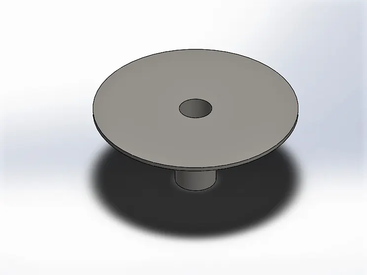
3.1.5 Valve Mount: Valve mount is used to actuate the valve with the help of spring. Similar to other parts, to get valve mount we sketch on the front plane and using revolve options available in the features.
3.2 Assembly:-
To do assembly we are going to import different parts of piston assembly in SolidWorks. the first part imported is always fixed in Solidworks, so by right click on the component, we can make it float. first, we are imported Cam, which is used as a basis for our assembly. after that, we are using a mate option to align crank properly in a 3D plane. similarly, we imported all the components of the piston assembly and assemble them with the help of the Mate option.
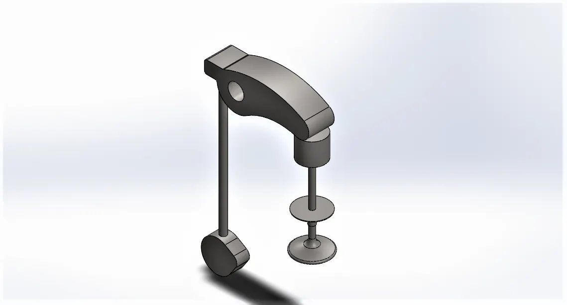
Note:- In the Mechanism, we need to Design the spring. But in Solidworks, we used the spring tool to do this which creates the imaginary spring in our mechanism. the imaginary spring works as a real spring which is adjustable in the SolidWorks.
3.3 Cam lift And Valve lift Calculation:-
3.3.1. Cam Lift:-
a. Theory:
This is the distance the cam lobe rises away from the base circle of the camshaft. It is the distance the lifter will move. It is also called "lobe lift." A more cam lift means the valve will open further.
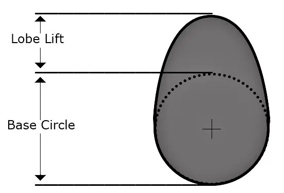
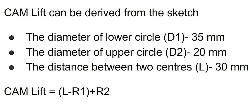
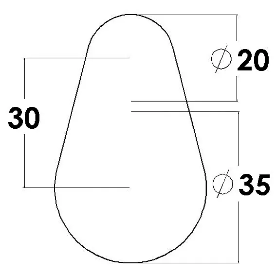
Here we need to calculate the center distance between the two circles of the cam. We have diameters of two circles of cam and cam lift for two different cases. So, by using the following formula for cam lift we can calculate the center distance between the two circles.
Formula For Cam Lift:
b. Calculation:
i. for Case-1:
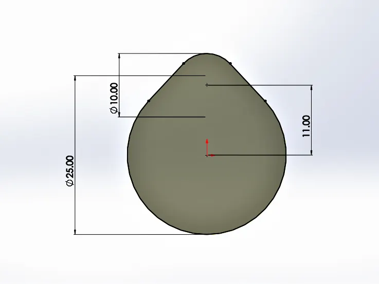
We have, Cam lift = 3.5 mm ; Major Circle Radius (R1) = 12.5 mm ; Minor Circle Radius(R2) = 5 mm
Therefore, using a formula,
Cam lift = `(L-R1)+R2`
`3.5 = (L - 12.5) + 5`
`L=11`
Modification in Cam for case-1:
ii. for Case-2:
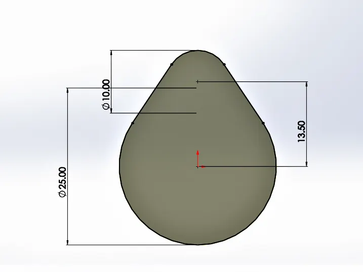
We have, Cam lift = 6 mm ; Major Circle Radius (R1) = 12.5 mm ; Minor Circle Radius(R2) = 5 mm and centre distance between circles (L)=?
Therefore, using a formula,
Cam lift = `(L-R1)+R2`
`6 = (L - 12.5) + 5`
`L=13.5`
Modification in Cam for case-2:
4. Simulation and Analysis:-
For Simulation and analysis, we are using the Solidworks motion analysis tool. In this are taking cam axis as a rotation axis and provided 1500 RPM. for smoother and more accurate values we took 7200 frames per second with precise contact. Selecting three contact pairs such as contact between cam and push rod, pushrod and rocker arm and rocker arm and valve. selected material as Cast Carbon Steel.
We need to assign the spring between the valve mount and valve. Hence we are assigned the linear spring with spring constant as 10 N/mm. we took gravity in the y-direction.
The Approach used to perform the simulation and its output is as shown in the table.
| Approach | Details |
| 4.1 valve lift | A plot of Valve lift at Cam lift 3.5 mm and 6 mm |
| 4.2 Plot of Contact force for Case-1 | Contact force for the cam lift 3.5 mm |
| 4.3 Plot of Contact force for Case-2 | Contact force for the cam lift 6 mm |
| 4.4 Plot of X-direction Contact force for Case-3 | The contact force between the Rocker arm and valve in X-direction. |
[Note:-1. to select the material, select the whole assembly, and right-click on the vacant window and select the material editing option. from here we can find out our desired material.
2. Be Careful while Selecting spring. select spring constant (k) in such a way that the value is practically driven. Otherwise, the whole assembly will get damage in simulation and in actual working conditions.]
After completing all the setup and completing calculation we are ready to plot the different results of plots. The Basic animation indicates the motion of assembly is as shown below.
Basic Motion Animation:
To plot the different result we have three different cases based on cam lift as we calculated before and modified cam geometry. First, we need to plot the valve lift which is as discussed follows.
4.1 Valve Lift:-
Valve lift is the distance the valve actually moves. It is also called "gross lift." To calculate it we are using a plot of Magnitude of linear displacement of Valve.
Case-1 Valve lift at Cam lift 3.5mm and L=11mm
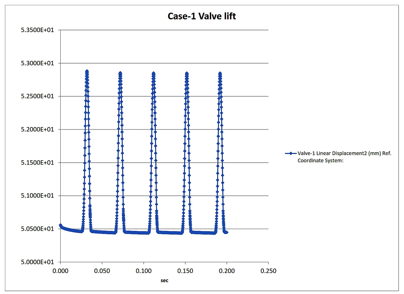
from the plot, the valve lift is nearly equal to the 5.28mm which is low due to the low cam lift.
Case-2 Valve lift at Cam lift 6mm and L=13.5mm
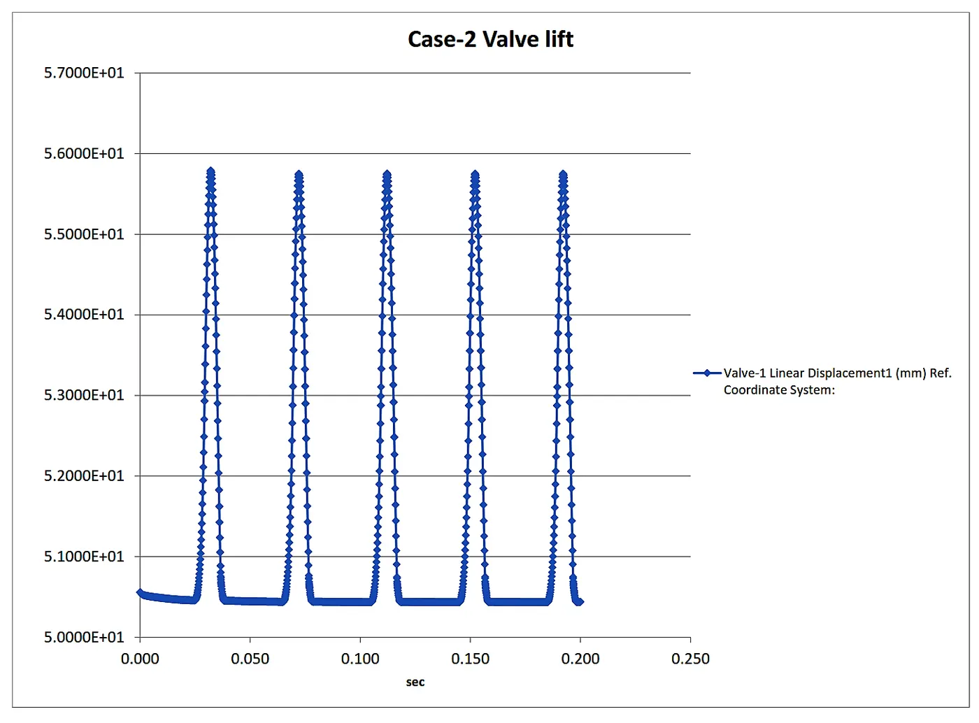
from the plot, the valve lift is nearly equal to the 5.58mm which is high due to the high cam lift.
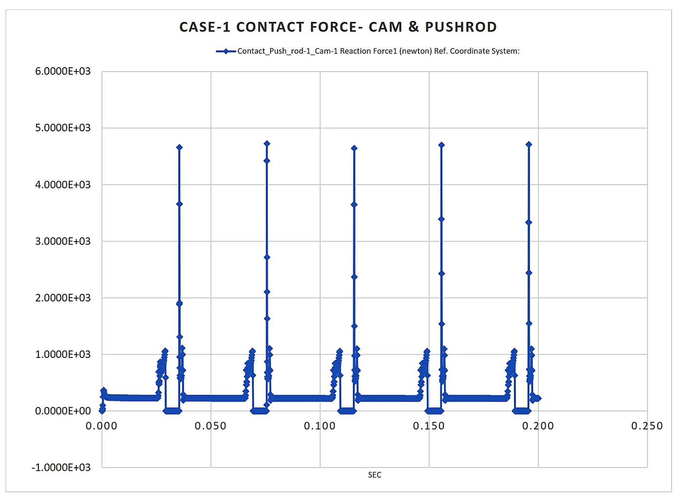
4.2 Plot of Contact force for Case-1:-
i. Contact force Between Cam and Push Rod.
ii. Contact force Between Pushrod and Rocker Arm.
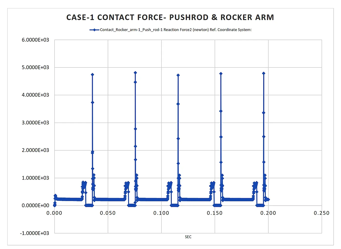
From the above two plots of contact force between the parts, we can see that the contact force is nearly the same in both cases. This indicates that the perfect transmission of force from the cam to pushrod and pushrod to the rocker arm.
iii. Contact force Between Rocker Arm and Valve.
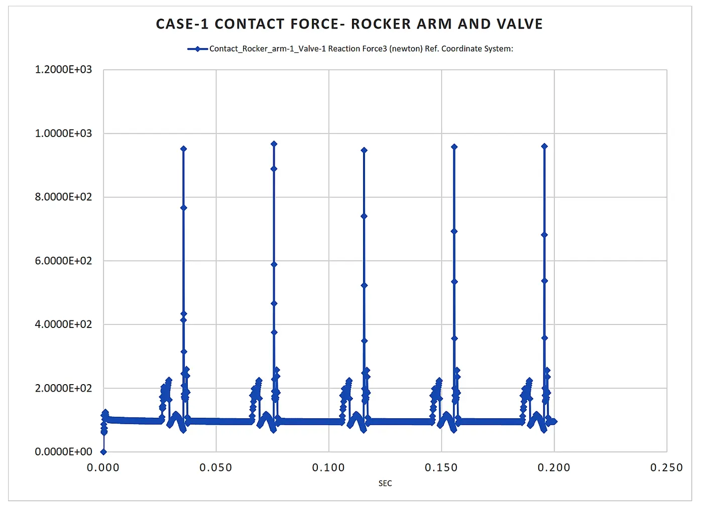
Similar to the first two plots, the third plot of contact force between a rocker arm and Valve indicates similar behaviour but the change in magnitude. Here, the magnitude of a contact force is less as compared to the other two cases which are caused due to imaginary spring attached to the valve. the spring used to make the mechanism consistent and also acts as a shock absorber. This leads to degrading the contact force.
4.3 Plot of Contact force for Case-2:-
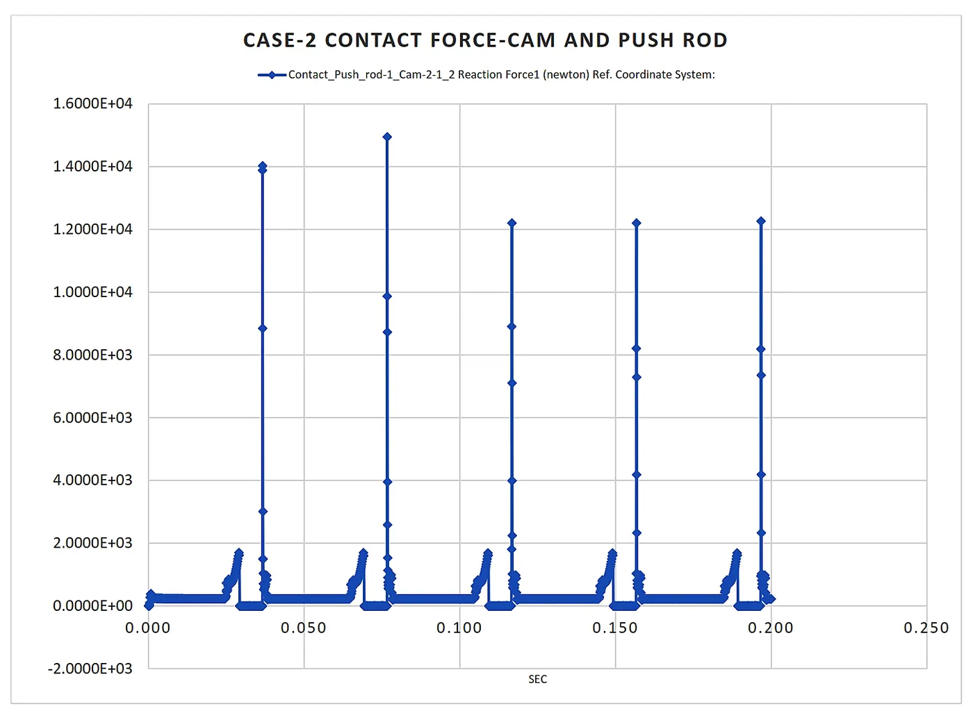
i. Contact force Between Cam and Push Rod.
ii. Contact force Between Pushrod and Rocker Arm.
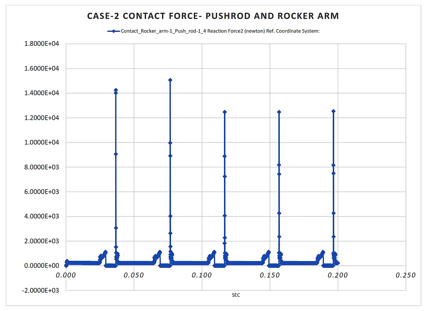
Similar to plots of the contact force between the parts of case-1, we can see that the contact force is nearly the same in both cases. This indicates that the perfect transmission of force from the cam to pushrod and pushrod to the rocker arm.
But in this case, we get the sudden increment in the contract forces from 0.03 to 0.045 seconds of cycle time. This indicates that the sudden impact force caused due to higher value of cam lift causes the Detachment of pushrod from the cam.
iii. Contact force Between Rocker Arm and Valve.
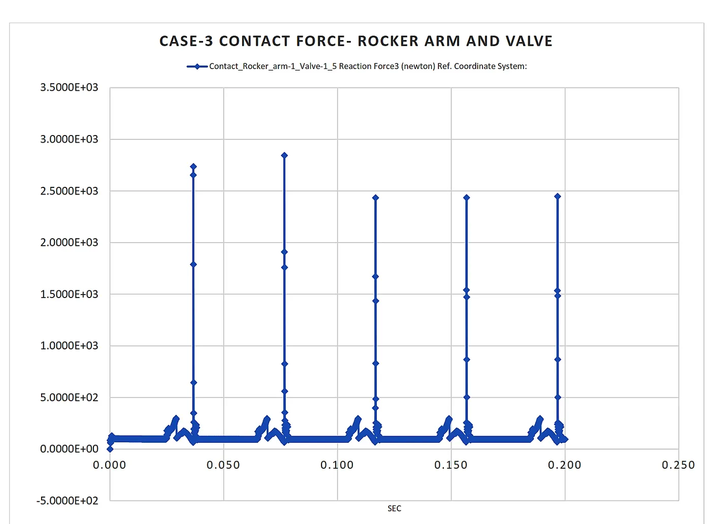
From the above three plots of contact force between the parts, we can see that the contact force is high with respect to the case-1. This is due to the high cam lift which causes high valve lift and higher impact force between parts.
4.4 Plot of X-direction Contact force for Case-3:-
The contact force between the Rocker arm and valve with respect to the X-direction is frictional. which is caused due to force acting while sliding of rocker arm on the valve as shown below.
5. Result and Conclusion:-
i. From the plots, we can conclude that as the cam lift increases the valve lift is also increases. the valve lift mainly depends upon the length of the rocker arm and cam lift. Also, the increase in cam lift causes an impact between the pushrod and cam. Hence the vibration and noise may be induced in the assembly which can be minimised by changing the cam lift parameters.
ii. The contact force between the Rocker arm and valve varies while measuring concerning the X-direction. because the frictional force acting between them while sliding of rocker arm on the valve.
iii. The contact force between the Rocker arm and valve is constant while measuring with respect to magnitude. because, while measuring the magnitude the net force acting on the bodies is taken into consideration.
iv. The transmission of force is ideally perfect i.e negligible losses of force in between a rocker arm and Valve. But in the case of contact force between a rocker arm and valve, the magnitude of a contact force is less as compared to the other two cases which are caused due to imaginary spring attached to the valve. the spring used to make the mechanism consistent and also acts as a shock absorber. This leads to degrading the contact force.
References:-
https://help.summitracing.com/
https://en.wikipedia.org/wiki/Valvetrain
The flow of Report:
1. Basic.
2. Objective
3. Procedure.
4. Simulation and Analysis.
5. Results and Conclusion.