Week 6 - Creating connection for Rear door
Week 6 Challenge: Creating connection for Rear door
Aim: Assigning different PIDs for different components and deploying connections between different components for the given Sode Door meshed model.
Given meshed model: Side Door meshed model
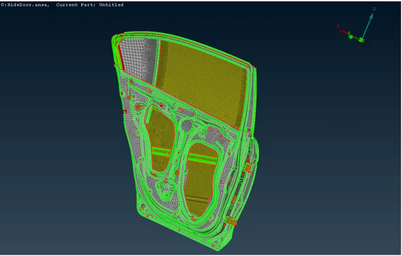
Procedure steps followed:
- Assigning different PIDs for different components.
- Deploying Bolt connections.
- Deploying spot weld connections.
- Deploying Bush connections.
- Deploying mass connection.
Procedure:
- Assigning different PIDs for different components.
For given model for deploying different connections, different PIDs are needed to be assigned.
This is done by MESH Deck -> Macros -> Set PID -> Faces
Using feature angle for selecting component Faces and confirming it.
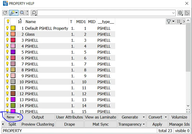
Using New -> PSHELL a new PID is assigned for selected Faces.
After assigning different PIDs final components is as shown below
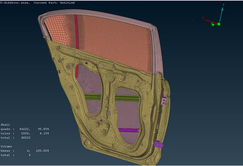
2. Deploying Bolt connections.
After assiging different PIDs, identifying where bolt connectioins can be deployed
- Two holes overlapping in different planes of two different PIDs
There are multiple ways of deploying bolt connects
- Using Connection Manager
- Using Nastran Deck -> Elements -> RBE2 -> Many Nodes and Two Nodes
- Using Connection Manger
Using TOPO -> Points -> On COG -> selecting hole using LOOP and confirming it,
3D Point is generated and converting it to Bolt using 'Convert'
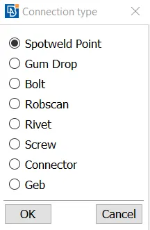
It appears as
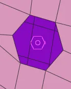
By using 'Connection Manager' this bolt is used to deploy connection
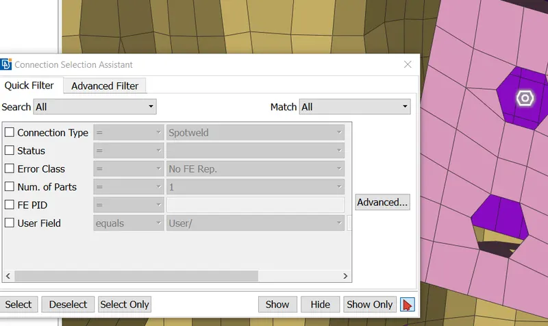
After selecting and confirming the bolt connection
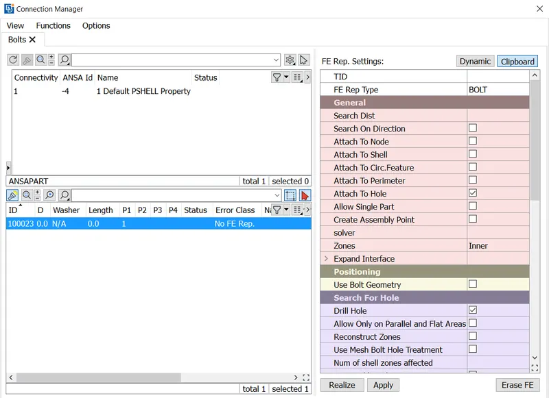
Selecting P1 and P2 and So on, for confirming the components between which the connection is deployed.
After giving Search Distance and using 'Realize' Bolt connection is deployed.
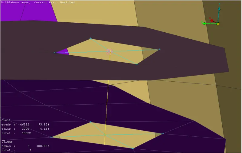
Bolt Connecting using 1D element
b. Using Nastran Deck -> Elements -> RBE2
Using RBE2 -> Many Nodes
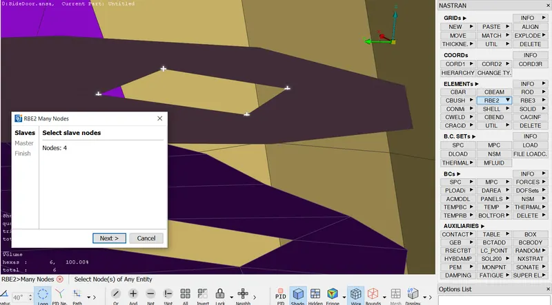
Selecting Slave Nodes using Loop and confirming it
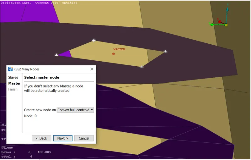
So, a RBE2 connecting is deployed for many Slave nodes and 1 Master Node
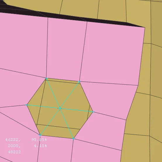
Using RBE2 -> Two Nodes we can deploy a 1D Element between two nodes a bolt connection is deployed.
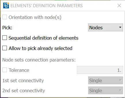
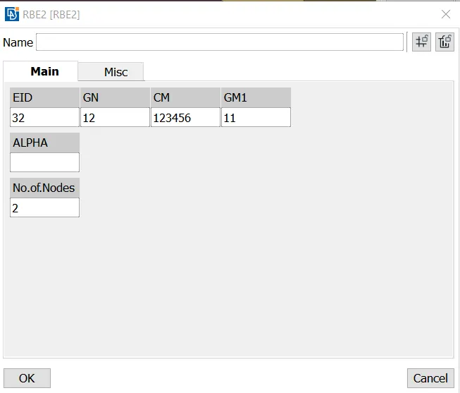
GN and GM1 is the Node ID and CM is Degree of Freedom constrained.
3. Deploying Spot Weld Connection
Similar to Bolt connection a 3D point is generated first and using Connection Manager a Spot Weld connection is Deployed
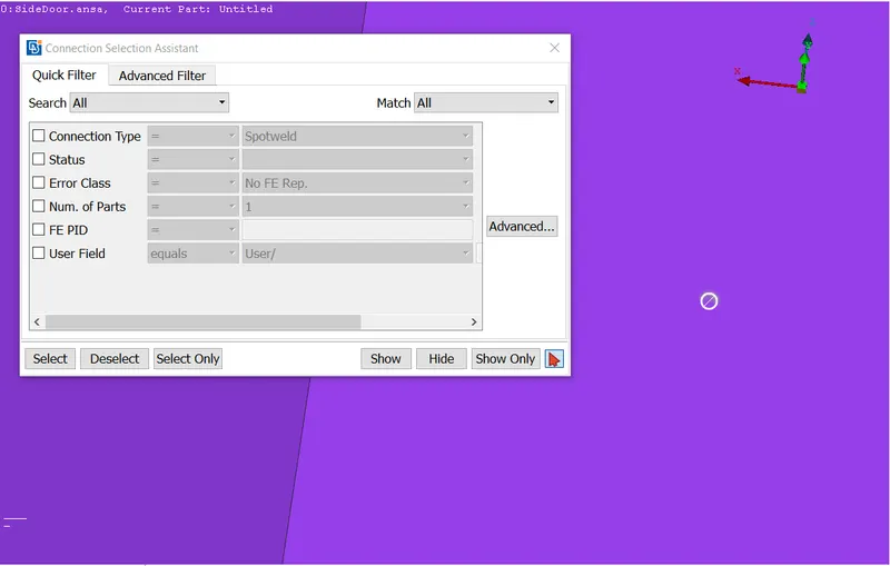
Selecting Spot Weld Point and Confimring it.
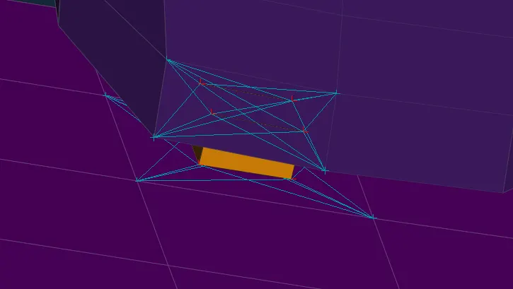
The element used is RBE3 - Hexa - RBE3
The Deployed Spotweld is shown below
4. Deploying Bush Connection
Here for deploying Bush connection for glass, we need a Spotweld Line
This is done by Using Mesh -> Perimeters -> Feature2Curve
a Curve is generated and using Convert a Spotline is generated similar to Bolt and Spotweld Connection.
Using Connection Manager and using CBUSh element we generate a Bush Connection.
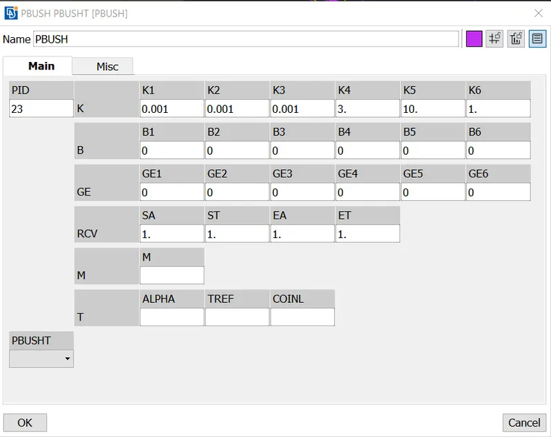
The stiffness K for all DOF is predefined.
Deployed Bush connection is Shown below
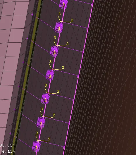
This Bush is arranged in same direction by changing
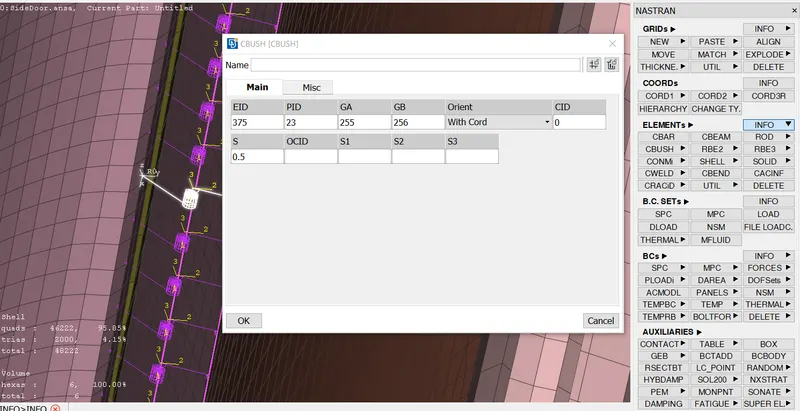
'Orient -> With Vector ' from Nastran -> Elements -> INFO to 'With Cord' and changind CID to the direction required.
5. Deploying mass connection
Some parts which are not necessary are modeled by concentrating the mass of that component at a node.
This is done by Nastran -> Elements -> CONMi
We are deploying mass connection for Door Handle by RBE2 -> Many Nodes

Using RBE2 -> Many Nodes between two nodes of above RBE2 a central node at mid point is generated and CONMi is deployed at that mid point.
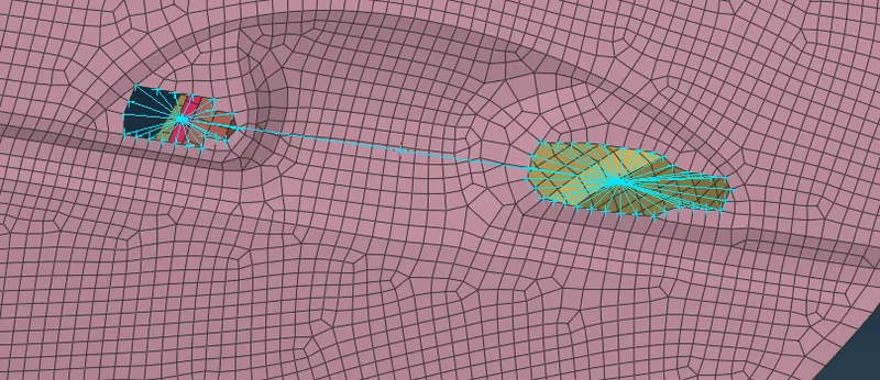
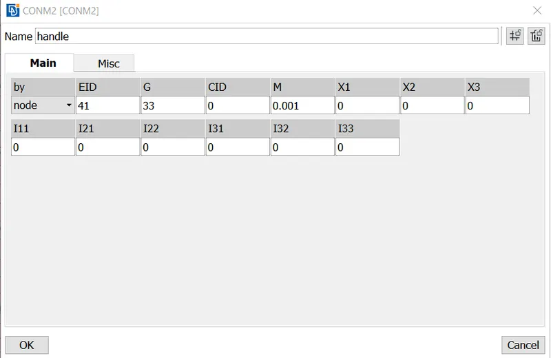
Here M is Mass of the component and it is given in Tonnes.
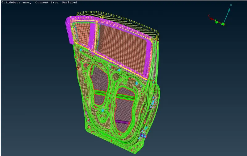
The final Side Door model after deploying connection is shown below
Learning Outcomes:
- Assigning Different PIDs
- Deploying BOLT, Spotweld and Spotline connection using Connection Manager
- How to effectively use CONMi, RBE2 from Nastran Deck -> Elements
- Converting 3D Points, curves to Bolt, Spotweld and Spotlines
Conclusion:
Assigning of PIDs and deploying of connections is done using ANSA v22.0