Creating connection for Rear door
Aim-
To deploy appropriate 1D connectors to the Rear Door model using ANSA.
Objective-
- To create separate PID's for individual parts of this car door.
- Creating RBE2 1D elements for bolt joints.
- Creating RBE2 on the door handle and then applying mass on the center.
- Creating RBE3-HEXA RBE-3 element for the spot weld joint.
- Creating RBE-3 CBUSH RBE-3 elements for weather strips.
Theory-
• Geometric entities that define connections between other entities
- Used for welding, bolts, adhesives, etc.
- Link geometry or FE entities
- Can be “realized” into FE representations of welds, etc. for any supported solver
- rigids, CWELDs, MAT100s, ACMs, etc
Types of Connectors-
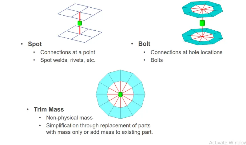
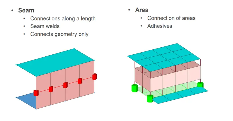
Link Entities - The entities that are being connected
• User can explicitly define link entities or specify a search tolerance
• Can be components, elements, surfaces, nodes, or tags
• Typically components are linked
Connector Location - Where the entities are linked
• Nodes – created at the node location
• Points – created at the point location
• Lines – created for the line
• line may be split into multiple projection locations as specified by the offset,
spacing, and density values
• Elements – created at the element location (adhesives only)
• Surface – created at the surface location (adhesives only)
Connector Realization – The creation of the finite element representation of that connector.
• Rigids, springs, etc., or custom configurations such as ACMs, CWELDS,
Types of connector state-
Connector State – Whether an FE representation of a connector has been created.
• Unrealized - The initial status of the connector entity upon creation.
• Realized - The status only if the creation of the FE weld representation at the
the connector was successful.
• Failed – The status of creating the FE weld representation at the connector
was not successful.
Procedure -
- The given Rear door model is opened in ANSA using the File -> Open option.
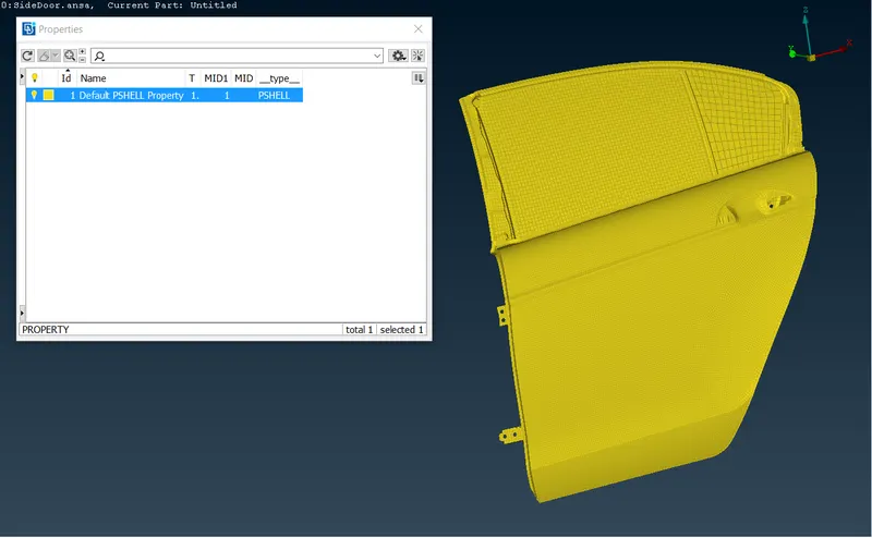
- When opened, the whole model was under one single PID. Therefore, the different parts of the model are arranged in separate PIDs.
Step 1: Deploying the Connections at Hinges:
Initially, the connections are deployed at the hinge regions. Which connects the door sub-system and the body of the car. The hinge region appears as shown in fig.
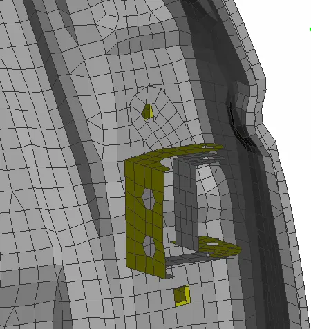
At the hinges, the bolted joint is used in the real scenario. So to replicate that virtually, the bolted joint is created. For creating a bolt connection, A COG point is required. Which is available in "Points" from the "Topo" module.
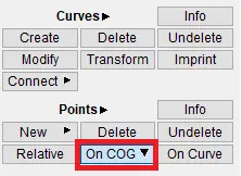
After selecting the COG option, any one of the closed perimeters should be selected.
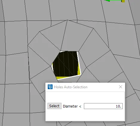
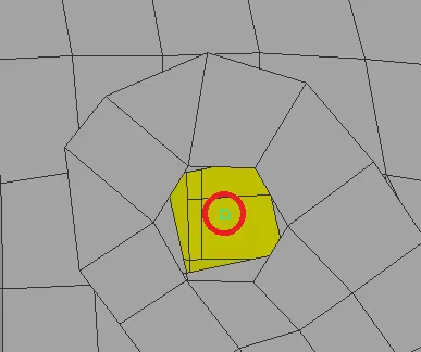
After selecting the closed perimeter by middle-clicking on the mouse, the COG point of that perimeter will be generated. Which is represented as a square with a sky-blue color, as shown in fig.
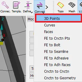
Then the created COG point should be converted to a 3D point from the "Convert" option in the assembly manager.
Then the 3D point should be selected and the bolt option should be selected. In order to convert the 3D point to bolt.
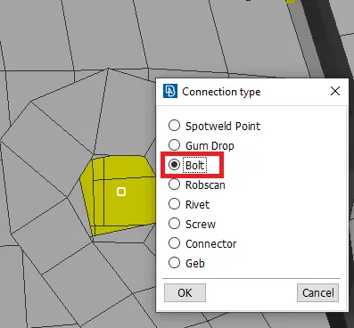
After converting the 3D point to bolt, the bolt will be represented as a hexagonal-shaped bolt.
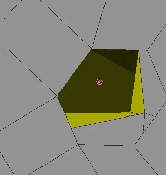
Then by using the "connection" option from the assembly manager, the bolt should be selected. The dialog box appears.
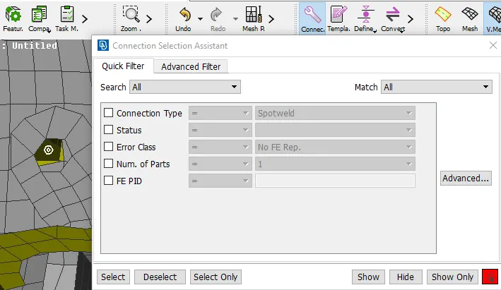
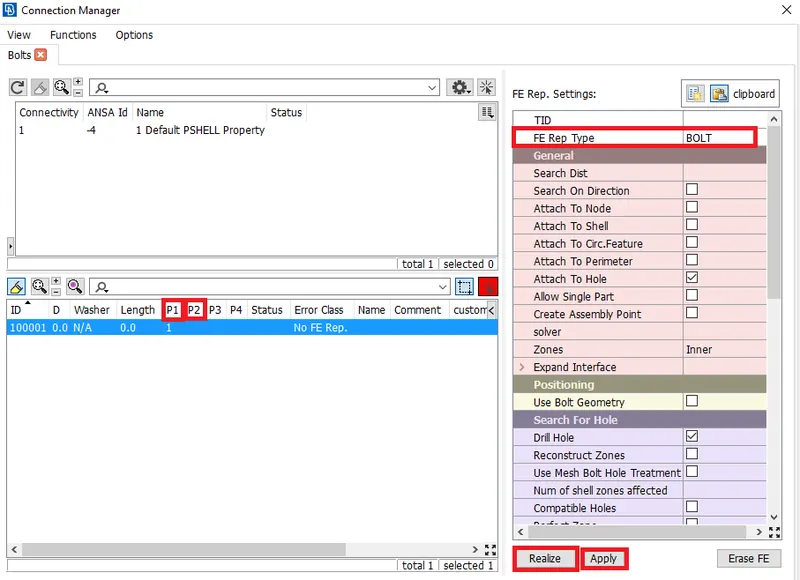
Then by middle-clicking, a dialog box appears as shown in fig. Which represents the connection manager. In which some parameters such as PID 1, PID 2, FE representation type should be selected. Then by selecting Apply, Realize the connection will be realized.
After realizing the connection, the formed bolt connection with the bolt stem appears as shown in fig.
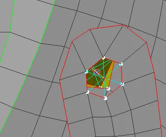
Then the connection is deployed using the RBE2 cluster in some regions. In which the RBE2 element---> Many nodes option should be selected. RBE2 cluster means, connecting so many nodes.
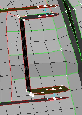
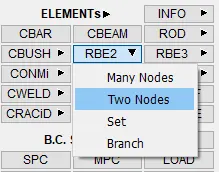
Then the RBE2 element, with two nodes option in the NASTRAN deck module is chosen. In order to connect the created RBE2 cluster.
After selecting the two nodes(i.e., Master nodes of the created RBE2 cluster), a dialog box appears as shown in fig. Which represents the info about RBE2 elements. In which, CM(Degrees of freedom) should be constrained in all directions except rotation in Z-direction(i.e., enabling CM only in 1,2,3,4,5). Because the door will be moved in rotation with respect to Z-axis.
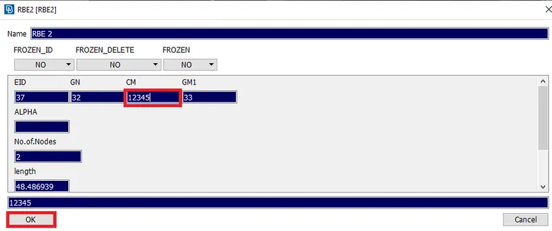
By clicking "Ok", the RBE2 element with 2 nodes is created in between two RBE2 cluster elements. Which is represented by a "Yellow" colored line.
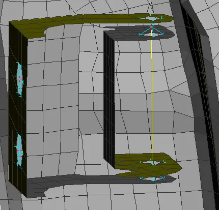
Step 2: Deploying the connections with RBE2 elements:
Similarly, the RBE2 elements are deployed in some regions. With many nodes option.
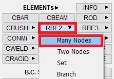
After selecting the many nodes option, The nodes should be selected as shown in fig. After selecting the nodes, by clicking on "Next" the slave nodes will be selected.
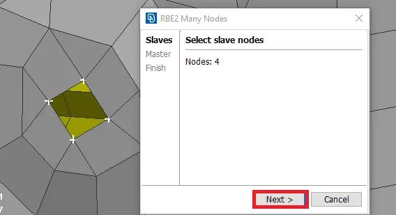
After selecting "Next", a dialog box appears. Which represents the method to create a master node. And the preview of the master node is also shown in red color.
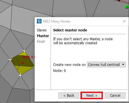
Then by clicking "Next", and RBE2 element will be created as shown in fig. And also shows the information regarding the created RBE2 element in a dialog box. By clicking "Finish", the connection will be realized completely.

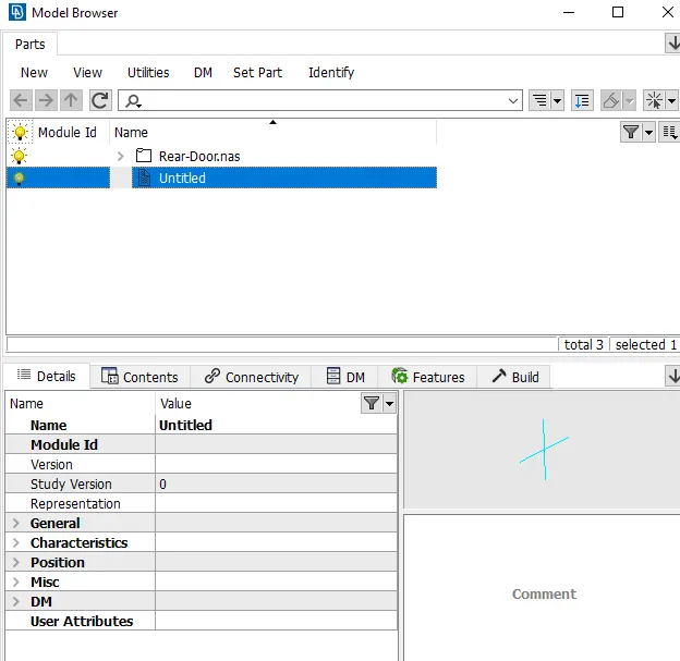
The created RBE2 links can be seen in the model browser.
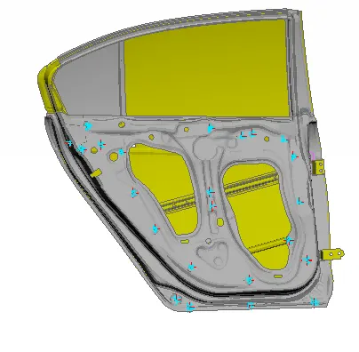
Similarly, the rigid(RBE2) elements are used to connect various PID's where the parts should be rigid enough at the time of the simulation. After deploying the connections with RBE2 elements throughout the model, the model with RBE2 elements appears as shown in fig.
Step 3: Deploying a connection at the door handle:
Then the connection is deployed at the door handle region.
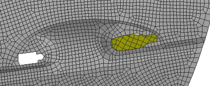
Initially, the RBE2 elements with many nodes options are used to connect all nodes at the perimeter of the handle. In order to possess the rigid nature.
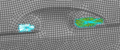
Then an RBE2 element with many nodes is used to connect both master nodes. After connecting.
Note: The reason behind using RBE2 with many nodes rather than RBE2 with two nodes is, to have a master node after connecting those two master nodes. But in the case of RBE2 with two nodes, there will be no master node after connecting those two portions.
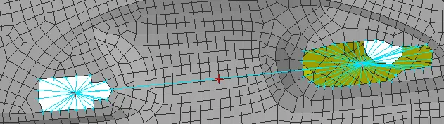
Then to represent the weight of the door handle, as in the case of a real-world scenario. The mass can be assigned by using the "CONMi" ---> CONM2---> Nodes. In the NASTRAN deck module.
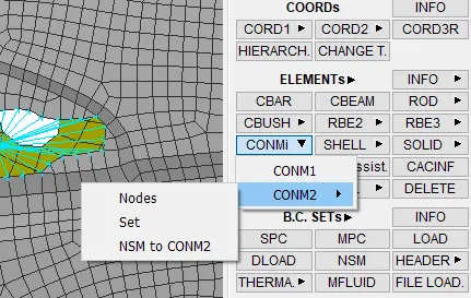
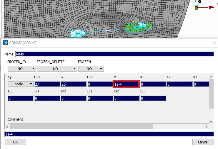
A weight is assumed as 1 kg and entered as "1e-4"(Which will be in the form of tonnes). And this is applied to the master node at the center.
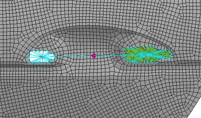
After assigning the mass at the center master node, it will be represented as highlighted.
Step 4: Deploying a Connection at the latch region:
As the latch is the part that is responsible for opening the door, it is connected by using the RBE2 element with many nodes to form a cluster.
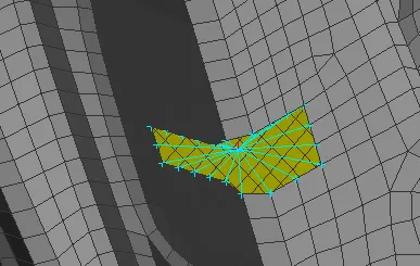
Step 5: Deploying a Connection between the rail & side glass:
In this step, the rail which is responsible for the movement of side glass up & down and the side glass are only isolated to have clarity on them.
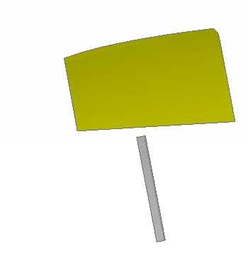
By isolating those components the thing noticed is, the rail component should be enlarged a bit more till the glass. This can be done by using the "Move free" option in grids from the mesh module. And the nodes at the edges are selected to enlarge in the z-direction.
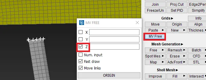
After enlargement, it appears as shown in fig.
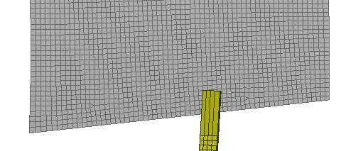
But the enlarged elements will be too high in terms of length. So, those elements are selected and reconstruction of elements is performed. By assigning the target element length, as by measuring any one element dimensions.
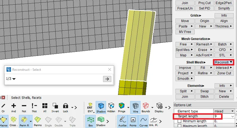
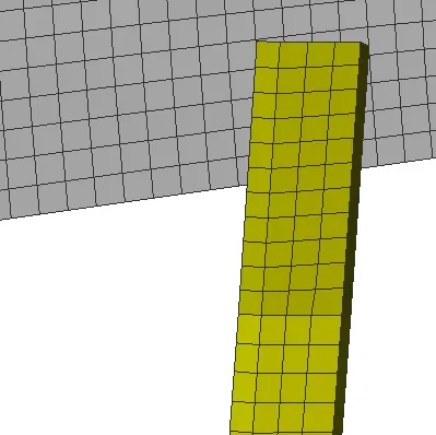
After performing reconstruction, the rail component appears as shown in fig.
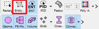
These two components are connected by using RBE2 elements. To possess rigid nature. So for proper selection of entities, the elements option is enabled. Which indicates the entities selected will be elements.
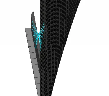
After selecting the elements and confirming the connection, the connection is deployed by an RBE2 cluster element between rail & glass.
Step 6: Deploying the connections using spot weld:
In some regions where the parts overlapped with each other with the minimal space between them is joined using the spot weld option. In order to represent the joint. So for creating a spot weld connection, the COG point is required. And the edges of the element are selected by choosing the "on COG" option.
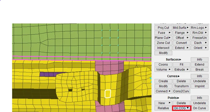
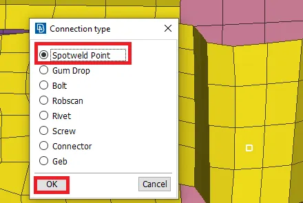
After creating a COG point, it is converted to a spot weld point. This is done by choosing, "Convert" option from the assembly manager. And in that, the connection type is specified as "spot weld point".
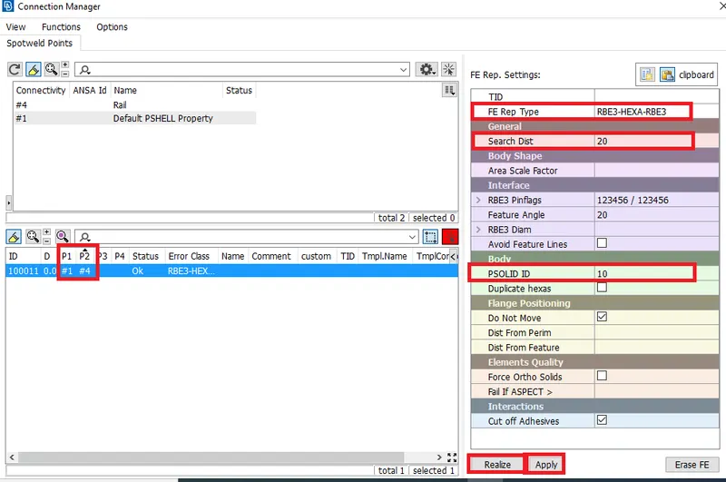
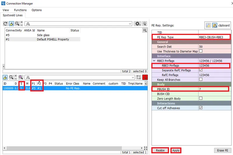
Then to realize this connection, the connection manager is opened from the assembly manager. And the converted spot weld point is selected. And some parameters are specified. And the FE representation of a spot weld connection in the NASTRAN deck is "RBE3-HEXA-RBE3".
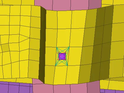
After realizing the connection, it appears as shown in fig. Similarly, the spot weld connection is deployed. Wherever it is necessary.
Step 7: Deploying the connections at the side glass region:
As the side glass is surrounded by a component called "Weatherstrip" which is made up of rubber material. And widely known as "Beading". So to represent that, the CBUSH elements are used. Because it possesses elasticity in all three directions.
So, initially, the curves are needed. For that, the "FEA to curve" option in the perimeters from the topo module is used.
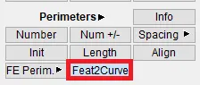
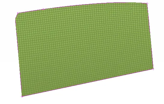
And the FEA edges are selected one by one and then it is converted into curves, which are represented by purple-colored lines at the edges.
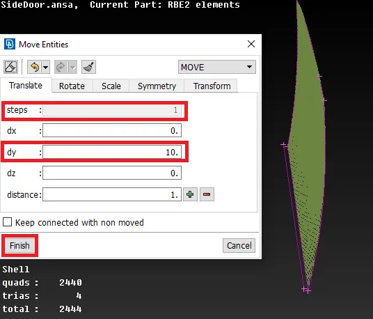
As the weatherstrips will be at both sides of the glass at the bottom, the CBUSH elements should be deployed at both sides of the bottom. For doing that, the curve created at the bottom should be copied by using "Transform" and moved to a certain distance such as 10mm.
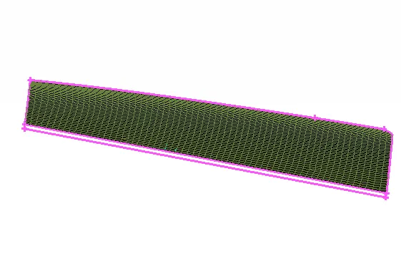
After copying & moving, the moving curve appears as shown in fig.
Then these curves are converted in to "spot line". And then this spot line is realized by selecting the line by line and specifying the parameters such as spacing between the CBUSH elements as 10 mm, specifying PART1 & PART 2, specifying FE representation type as "RBE3-CBUSH-RBE3" and assigning RBE3 pin flags(DOF) in all directions.
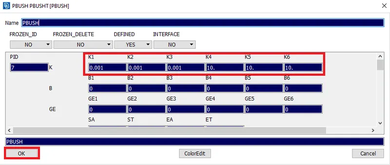
Then the PID should be created, which is done by selecting "Shift+?" from the key-board by placing the cursor in the PBUSH ID row. After selecting a "new" option, a dialog box appears as shown in fig. Which represents PID for the CBUSH elements. In that, the 6 stiffness values are entered, which are predefined.
After creating the new PID for CBUSH elements, the CBUSH elements will be formed in between the side glass and outer part.
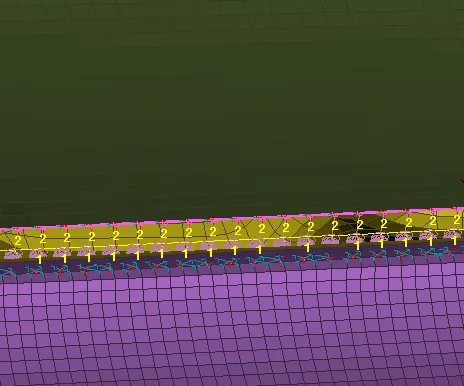
Similarly, the CBUSH elements are created on all sides of the glass. Then the created CBUSH elements are isolated. After isolating them the thing noticed is, the CBUSH elements are in different orientations. Which may lead to inappropriate results at the time of the simulation.
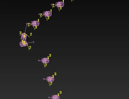
So to overcome that problem, the orientation of all CBUSH elements should be changed to that of a global coordinate system, For doing that, all of the CBUSH elements are enabled from the database window.
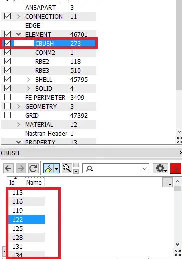
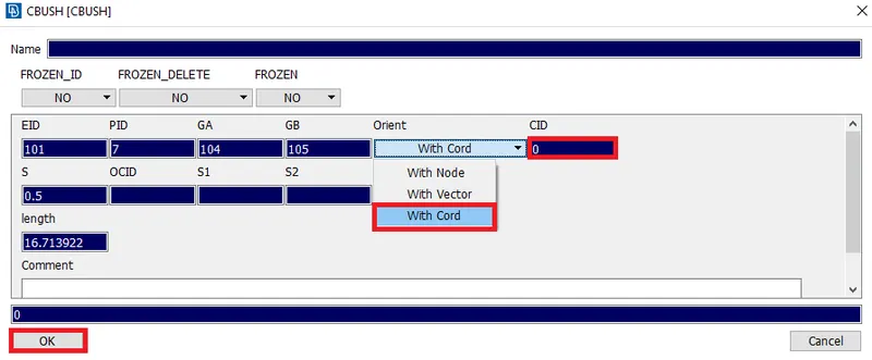
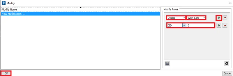
Initially, any one of the elements is selected and the orientation is chosen to "With Cord", which means "With respect to co-ordinate axis. And the CID is given as "0". The orientation with respect to global coordinates.
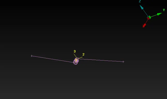
By isolating only that CBUSH element, the coordinates of that element will be changed to the same as that of global coordinates.
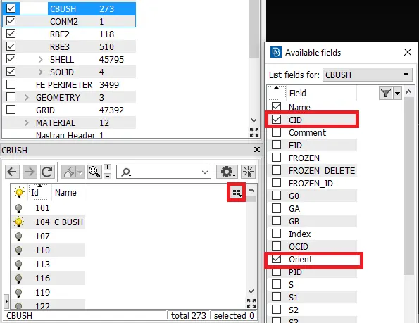
So for doing the same to all CBUSH elements, they are enabled. And by selecting the drop-down box which is highlighted in fig. The list fields to be included with the elements are shown. In that, CID & orientation are enabled. Thereby select the "modify" option in that CID region.
Then by clicking "Ok", a dialog box appears as shown in fig. Which indicates the selection of CID(Co-ordinate ID) for all elements. And the values are specified.
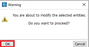
By clicking "Ok", a dialog box appears as shown in fig. Which depicts a warning message by indicating that the change in CID is ok to continue or not.
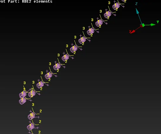
After clicking "Ok", all CBUSH elements will be in the same orientation.
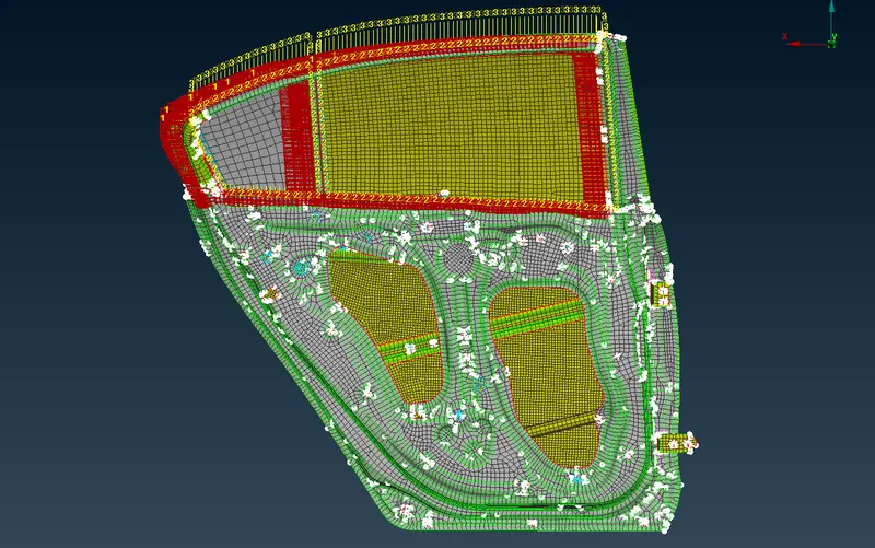
Final model with all appropriate connection's-
Learning Outcomes-
- How to make separate PIDs especially for connection types.
- How to make realized the connector successfully.
- How to debug a connector if it is failing from realization.
Conclusion-
- Finally, Deployed the necessary connections for the given meshed rear door model.