DOOR TRIM PANEL DEVELOPMENT
AIM: To Creation of CAD model considering Class A surface, Nominal thickness and Attachment strategy.
OBJECTIVES:
- To Creation of CAD model considering Class A surface, Nominal thickness and Attachment strategy.
- Create thickened part using master section for reference
- Create the mounting features as per design guidelines in the industry and with master sections
- Apply material details
- Draft analysis & Tooling analysis
INTRODUCTION:
10 Stages of Product life cycle of automotive Industry are
- Concept sketch
- Styling class A
- Feasibility check
- Concept validation
- New Product Design
- Product Development
- Proto Build
- Design Validation
- Pilot Production
- Mass production
- New Product Development CAD: This is the stage where the major work of product design, by taking inputs from the concept sketch to validate the product will go to design using design software such as NX, CATIA V5, Solidworks, Solid Edge etc. In this stage through design all the surfaces are divided into sub parts from the class A surface and ensuring product should be workable. Making the 3D model and 2D drawings for development. Here product design is going to complete 100%.
PROCEDURE:
- Class A Surface
In Automotive industry there will be a dedicated team who will perform the aesthetic designing of various components including the whole vehicle. They will create various concept sketches after ideation. After that, they will also create a Class A surface of the product. This class A surface is then passed over to the NPD CAD team. They will initially inspect the Class A surface in order to check if the design is manufacturable or if it is following the engineering principles. If there are any issues about the design, they will contact the product design team and will ask to modify the Class A surface in order to solve the problem. Here I received the Class A surface as shown below.
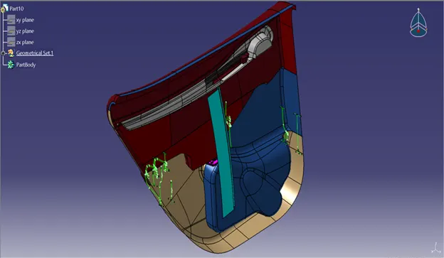
INPUT
Class A surface modification as per master section: From the given data we have to do cad model for Lower Substrate, Arm Rest and Map Pocket.
- MAP POCKET 1
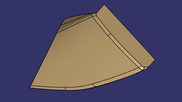
Initially, I extracted the Class A surface required for each part from the main input. Then started working on them one by one. Here I extracted the class A surface of map pocket from input as shown below.
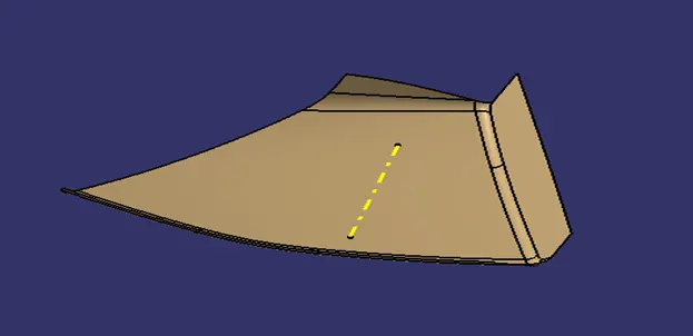
Next, main tooling axis was created by applying a zero-distance value on the surface as shown below.
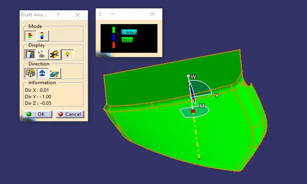
Next, the surface was inspected using draft analysis as shown below. In industry, if there is any issue with the surface after inspection, engineers must discuss the issue with the aesthetic design team whom provide the class A for troubleshooting the issue.
Class B surface development
Class B surface was created from the class A surface using offset at a distance of 2.5 mm thickness.
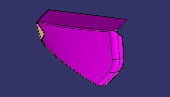
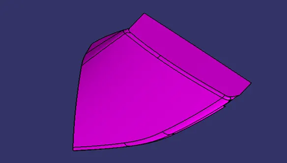
Class C surface development
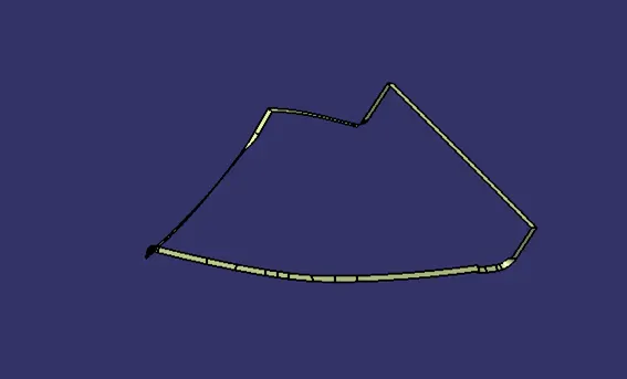
Class C surface was swept along the boundary of Class A using ' Sweep' option at an angle of 3 degree outwards with respect to tooling direction. In some areas 90 degree sweep was applied. Finally, all the swept surfaces were trimmed and joined together.
Then, class A surface of map pocket 1 and the Class C surface were joined together as shown below.
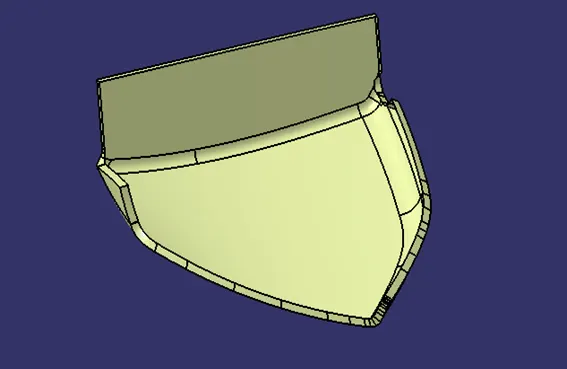
After joining Class A and C surfaces, it was trimmed together with the Class B surface in order to form the closed surface as shown below.
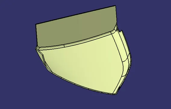
A part body was formed using the closed surface. Next step was the creation of mounting features for fixing the component on the lower substrate.
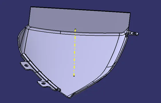
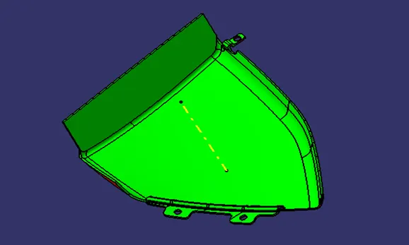
Finally, draft analysis of the component was successfully performed.
- MAP POCKET 2
Map pocket 2 was also created by following the same steps and procedures. Initially class A surface was extracted from the input surface as shown below.
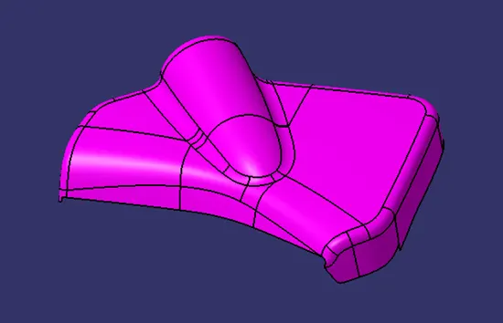
Next, I created tooling axis for map pocket 2.
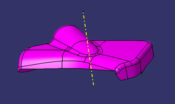
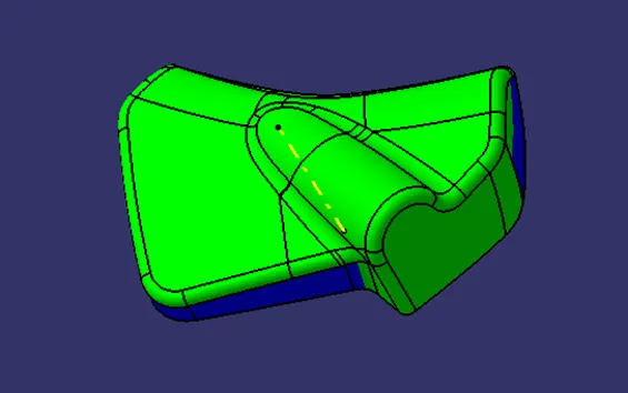
Next, the surface was inspected using draft analysis as shown below. In industry, if there is any issue with the surface after inspection, engineers must discuss the issue with the aesthetic design team whom provide the class A for troubleshooting the issue. The walls were below 3 degree (blue). If it is an industrial project, we must discuss it with aesthetic design team in order to avoid this issue by modifying the surface. But it is acceptable in this project. Green surface represents more than 3 deg angle.
Class B surface development
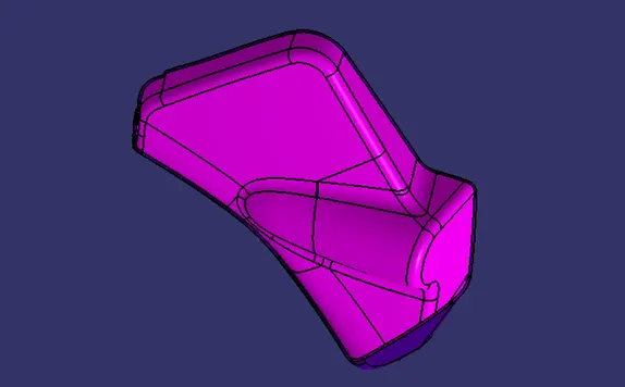
Class B surface was created from the class A surface using offset at a distance of 2.5 mm thickness.
Class C surface development
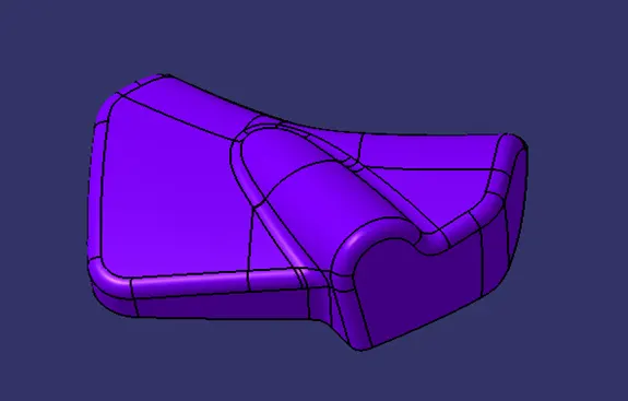
Class C surface was swept along the boundary of Class A using ' Sweep' option at an angle of 3 degree outwards with respect to tooling direction. In some areas 90 degree sweep was applied. Finally, all the swept surfaces were trimmed and joined together.
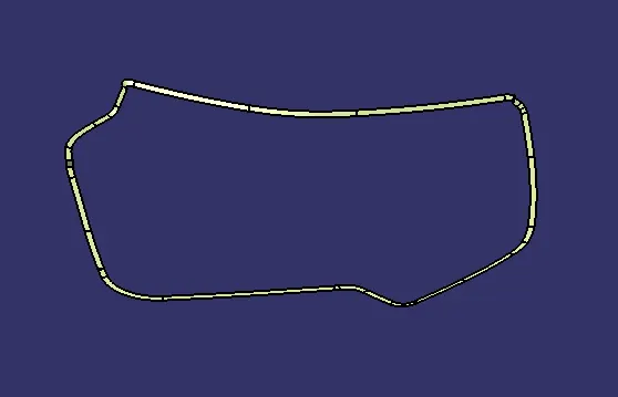
Then, class A surface of map pocket 2 and the Class C surface were joined together as shown below.
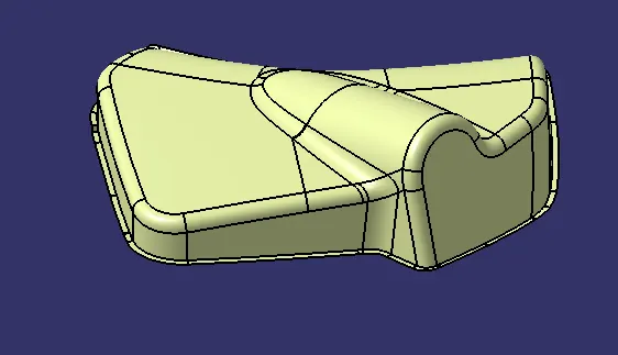
After joining Class A and C surfaces, it was trimmed together with the Class B surface in order to form the closed surface as shown below.
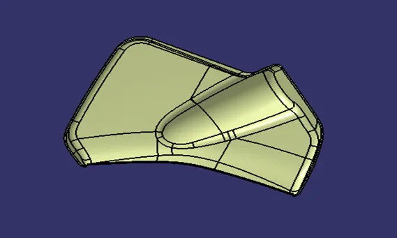
A part body was formed using the closed surface. Next step was the creation of mounting features for fixing the component on the lower substrate.
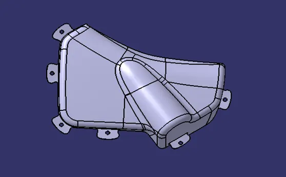
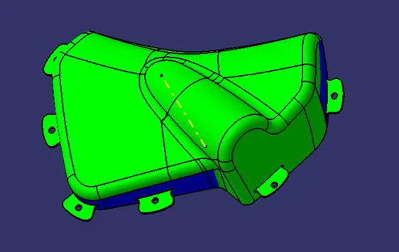
Finally, draft analysis of the component was successfully performed.
- ARM REST
Arm rest consist of two split parts. As the tooling was complicated if it manufactured as a single component, I split it into two.
Arm rest - Part 1
I extracted the required surface for class A of part 1 from the input surface.
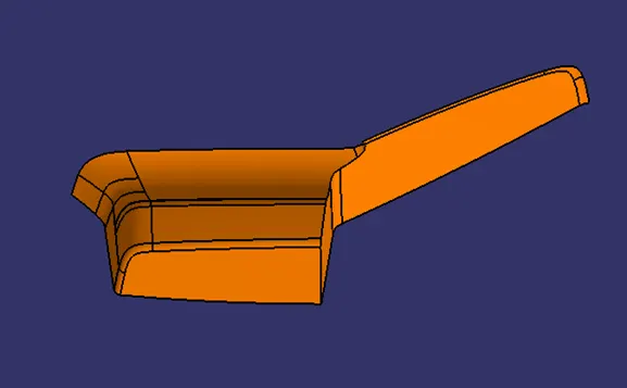
Next, I created tooling axis.
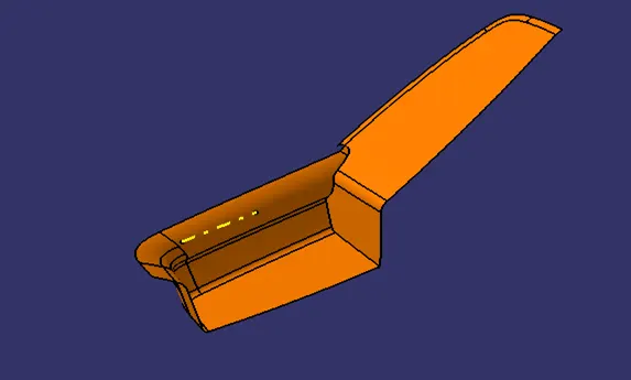
Successfully inspected the class A surface using draft analysis.
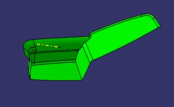
Class B surface development
Class B surface was created from the class A surface using offset at a distance of 2.5 mm thickness.
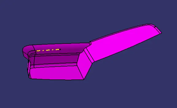
Class C surface development
Class C surface was swept along the boundary of Class A using ' Sweep' option at an angle of 3 deg outwards with respect to tooling direction. In some areas 90 deg sweep was applied. Finally, all the swept surfaces were trimmed and joined together.
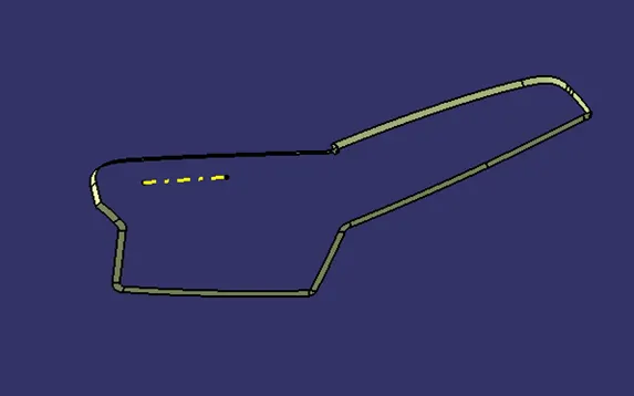
Then, class A surface of arm rest 1 and the Class C surface were joined together. After joining Class A and C surfaces, it was trimmed together with the Class B surface in order to form the closed surface as shown below.
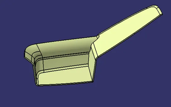
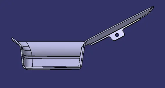
A part body was formed using the closed surface. Next step was the creation of mounting features for fixing the component on the lower substrate.
Arm rest – Part 2
The second part was also designed as the first one, following the same procedure.
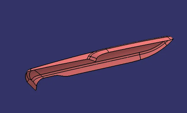
Next, I created tooling axis.
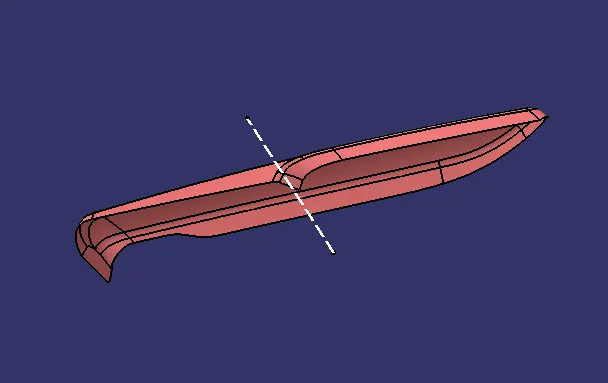
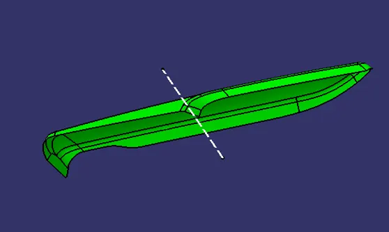
Successfully inspected the class A surface using draft analysis.
Class B surface development
Class B surface was created from the class A surface using offset at a distance of 2.5 mm thickness.

Class C surface development
Class C surface was swept along the boundary of Class A using ' Sweep' option at an angle of 3 deg outwards with respect to tooling direction. In some areas 90 deg sweep was applied. Finally, all the swept surfaces were trimmed and joined together.
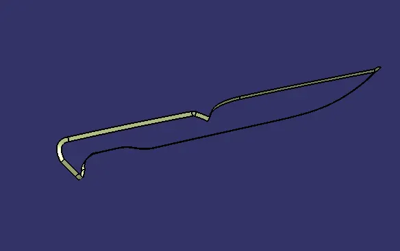
Then, class A surface of arm rest 1 and the Class C surface were joined together. After joining Class A and C surfaces, it was trimmed together with the Class B surface in order to form the closed surface as shown below.
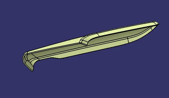
A part body was formed using the closed surface. Next step was the creation of mounting features for fixing the component on the lower substrate.
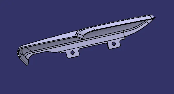
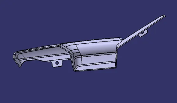
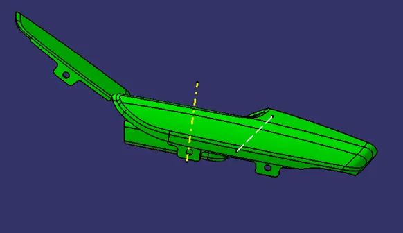
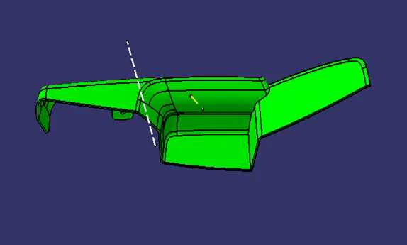
Finally, draft analysis of the component was successfully performed.
- LOWER SUBSTRATE
It is on the lower substrate all the earlier designed components going to fix at first. I extracted the surface for class A from the input surface.
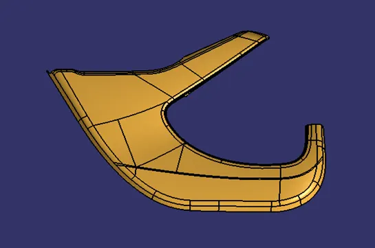
Next, I created tooling axis.
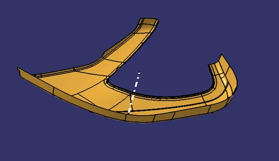
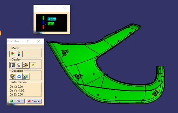
Successfully inspected the class A surface using draft analysis.
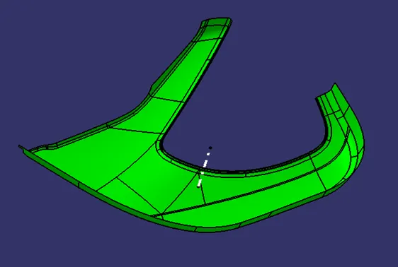
Class B surface development
Class B surface was created from the class A surface using offset at a distance of 2.5 mm thickness.
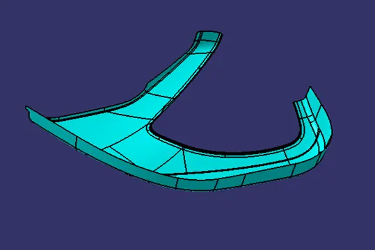
Class C surface development
Class C surface was swept along the boundary of Class A using ' Sweep' option at an angle of 3 deg outwards with respect to tooling direction. In some areas 90 deg sweep was applied. Finally, all the swept surfaces were trimmed and joined together.
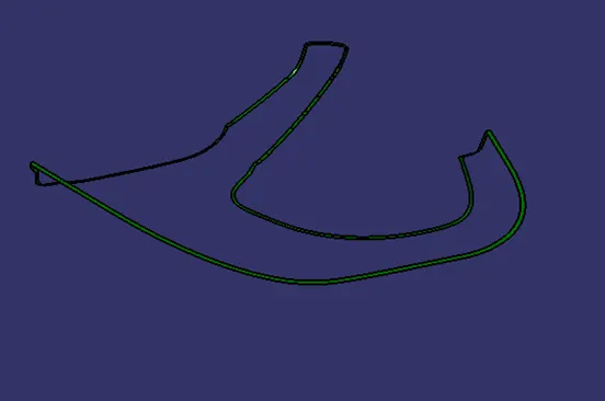
Then, class A surface of lower substrate and the Class C surface were joined together. After joining Class A and C surfaces, it was trimmed together with the Class B surface in order to form the closed surface as shown below.
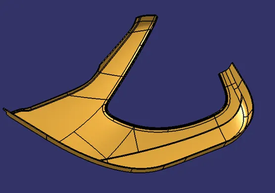
A part body was formed using the closed surface. Next step was the creation of mounting features for fixing the component on the lower substrate.
SCREW BOSS –
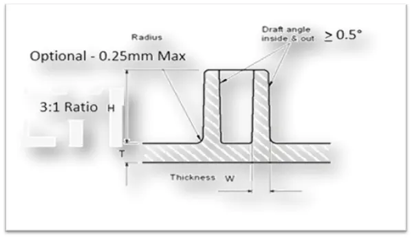
A boss feature finds use in many part designs as a point of attachment and assembly. The most common variety consists of cylindrical projections with holes designed to receive screws, threaded inserts, or other types of fastening hardware. Under service conditions, bosses are often subjected to loadings not encountered in other sections of a component. Provide a generous radius at the base of the boss for strength and ample draft for easy part removal from the mold.
GENERAL GUIDELINES FOR BOSSES –
- Draft - 0.5 degrees on walls of boss
- Thickness - Typically 40% of the nominal wall at the base.
- Height to Diameter Ratio - 3:1
- Radii - 0.25mm maximum radii.
DOG HOUSE –
It is a ‘doghouse’ looking embossment for screws to attach one piece of plastic to another one. For example, you have a bumper cover, and you want to add a garnish to it.
The shaded oval is where the screw comes in and, in this example, these doghouses are on the back of an a-surface bumper cover. Now the reason it's a doghouse is that you want to keep the legs of the doghouse thin so that there are no sink marks on the a-surface.
If a plastic component is too thick (as in where the a-surface thickness of 3 mm and the doghouse thickness of say 3 mm comes together, you would have a sink mark).
GENERAL GUIDELINES FOR DOG HOUSE –
- Doghouse wall thickness at the intersection of the part wall (C) should be 40% or less than the main wall stock (T).
- Height of (B) should be between 3.0 – 6.0 mm.
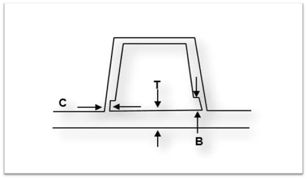
"C" is where the doghouse contacts the backside of the surface.
Thus, following all the above guidelines, I created the doghouse for locator pin as shown below.
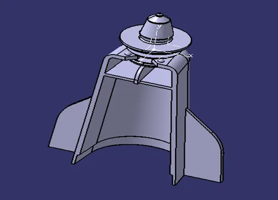
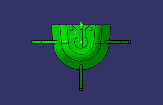
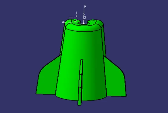
Then draft analysis of dog house is done for main tooling axis and side core axis.
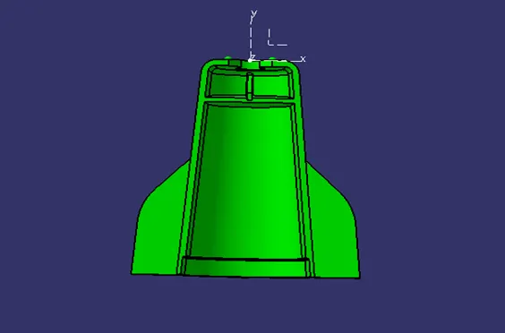
Then heat stakes are designed with 0.5 deg draft.
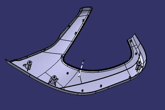
Draft analysis on the lower substrate was successfully performed with minimum 3 deg draft angle.
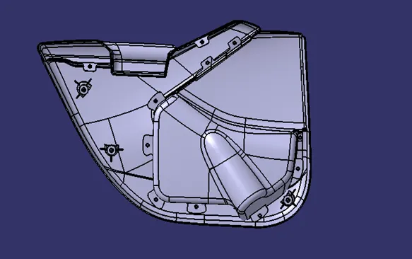
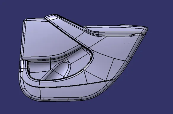
FINAL PRODUCT
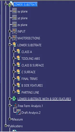
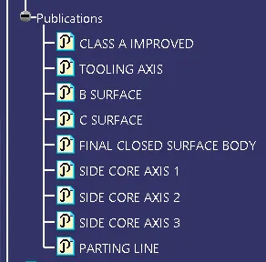
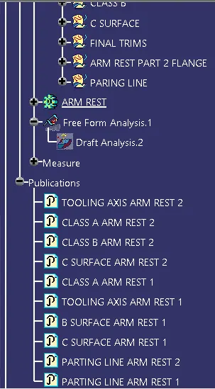
TREE STRUCTURE –
Lower Substrate
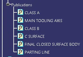
Map Pocket 1
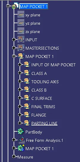
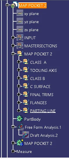
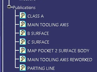
Map Pocket 2
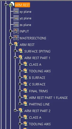
Arm Rest
CONCLUSION - Door trim panel is successfully created using Class A surface and master sections as input. And draft analysis is also performed successfully.