Week 6 - Creating connection for Rear door
Aim:
To create appropriate 1D connections for the given rear door FE Model.
Procedure:
Importing CAD model:
1. Import the CAD geometry in ANSA.
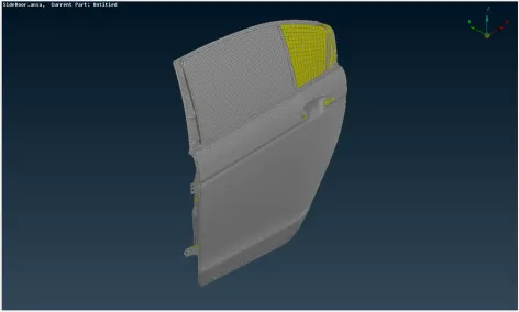
Figure 1 - Imported geometry of Rear door FE model
2. Separate PIDs were created and assigned to each of the bodies in the model
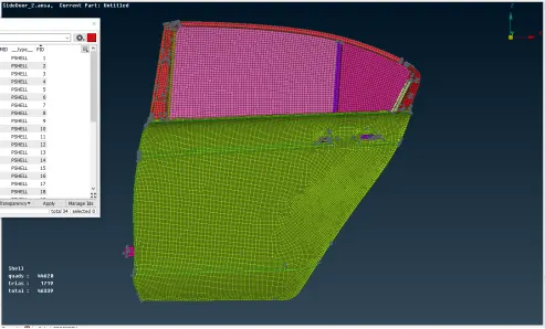
Figure 2 - Separate PID created for bodies in model
Door Hinge:
1D connectors are assigned to the door hinge as shown below:
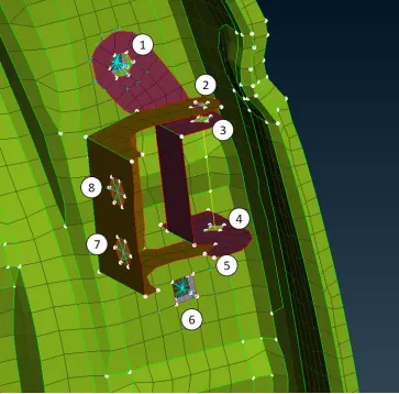
Figure 3 - 1D connector assigned to the door hinge
- Hole 1 clamps the hinge to the door through bolt. Therefore, RBE2 bolt connector is assigned and the procedure for it is as follows:
- 3D point is created on the top hole using Topo --> Points --> On COG
- The point is changed to Bolt representation using Convert --> 3D Points --> Bolt
- Using Connection Manager --> Select Bolt point --> Select the mating parts P1, P2,… --> Select FE Rep type as Bolt
- Select the zones (In/Out, Inner, …)
- Since, the bolt is used to clamp the parts together, bolt geometry is not checked
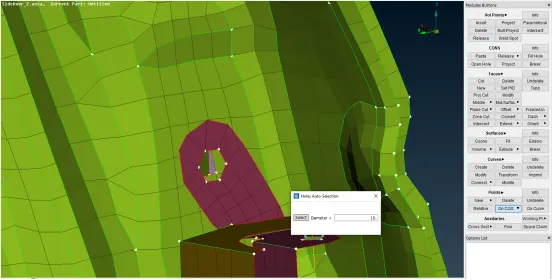
Figure 4 - COG Point creation

Figure 5 - Assign a Bolt connector
- Hole 2, 3, 4 & 5 are assigned with two node RBE2 element in the NASTRAN tab with DOF “12345”. The number 6 has been removed since it represents the rotational motion of the door hinge with respect to the body hinge
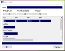
Figure 6 - Two node RBE2 element
- The holes 7 & 8 of body hinge are assigned with many nodes RBE2 element using NASTRAN --> Elements --> RBE2 --> Many Nodes --> Select Slave nodes --> Check the position of Master Node --> Finish
Door handle:
The door handle is assigned with a concentrated mass instead of a door handle model as shown below:
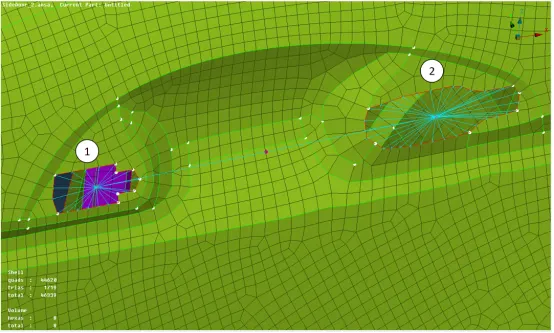
Figure 7 - Door Handle as concentrated mass
- For hole 1, select Nastran --> Elements --> RBE2 --> Many Nodes
- Select the slave nodes and repeat for hole 2
- Connect the center nodes of two holes using RBE2 element to get a master node (this represents the COG of handle)
- Select Nastran --> Elements --> CONMi --> CONMi 2 --> Nodes
- Select the master node created
- Enter the mass in “tonnes” (0.0001) in the property card
PBUSH Connection:
The glasses in the rear door are supported by strips of elastic material on all the sides and is located in between the door sheet and glass.
This is realized by PBUSH connection. The procedure is as follows:
- The outer contour of the glasses are converted to curves using Mesh --> Perimeters --> Feat2Curve
- Curves are converted to Spot line using Convert --> Curves --> Spot Line
- Select Connection Manager --> One of the created spot line. The below window opens:
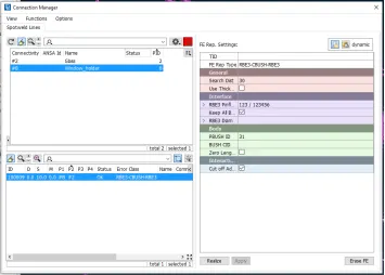
Figure 8 - PBUSH Connection Manager
- Select P1 for the part of the door which can contact the strip and P2 as glass
- Select FE Rep Type as “RBE3-CBUSH-RBE3”
- The option “Keep All Branches” are checked, since RBE3 element is used
- The PBUSH material is created with the following stiffness properties:
|
K1 |
K2 |
K3 |
K4 |
K5 |
K6 |
|
0.001 |
0.001 |
0.001 |
10 |
10 |
10 |
- Select “Realize” option to complete the process
- The CBUSH element by default is oriented with Vector. This causes the bush elements in each edge of the glass to be aligned in different X,Y,Z directions. Hence, they were changed to “With Cord” to align all the elements to the global coordinate system of the vehicle
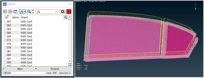
Figure 9 - PBUSH Connection for weather strips
Spot weld connection:
Several parts of the door are joined by spot weld. This is realized in the following procedure:
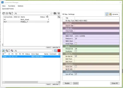
Figure 10 - Spot Weld connection manager
- The COG point is created using Topo --> Points --> On COG --> Edges
- The point is then converted to spot weld using Convert --> 3D points --> Spot weld
- Then, select Connection Manager --> Select the spot weld point --> Select P1 & P2 bodies --> Enter FE Rep Type as “RBE3-HEXA-RBE3” --> Choose / Create PSOLID ID --> Realize
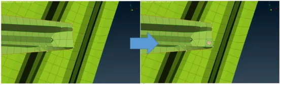
Figure 11 - Spot weld connection
Final completed model:
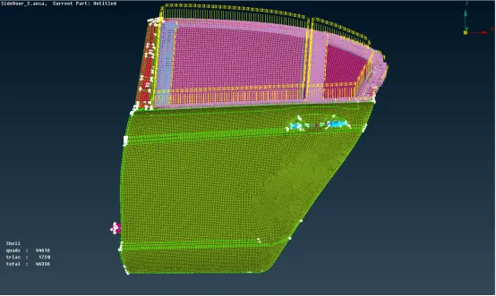
Figure 12 - Completed model 1
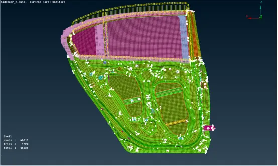
Figure 13 - Completed Model 2
Learning Outcomes:
Assignment of different 1D connectors to a model using the elements in Nastran tab and Connection Manager.
Conclusion:
Thus, the given rear door FE Model have been assigned with appropriate 1D connections.