Week 6:- Clamp Unit & Pin-Clamp Unit Design Challenge
Aim: Design 3 different types of clamp units and a clamp-pin unit.
Clamp Unit Basics:
- 3-2-1 Principle: This principle is used for locking the 6 degrees of freedom of the component. A resting unit locks 3 degrees of freedom. The up and down movement and 2 rotational degrees of freedom.
- For locking all 6 degrees of freedom, 3 supports are placed to form the first datum.
- Next, we add clamping units to and add minimum of 2 pin units to arrest all 6 degrees of freedom.
- Forces on Clamp Units: Clamping force: It is the gripping forces acted on the panel due to the gripping of the clamping mylar. Holding Force: it is the maximum force by the resting mylar after locking it into position. It is an important factor and if the force level is exceeded then it can cause distortions in the components after procedures like welding are carried on it.
Factors to consider while designing clamp unit:
- There should be enough space between the cylinder and other parts for free and correct movement of the calm arms.
- The contact area for stopper-clamp arm and the cylinder-clamp arm should be finished surface for smooth motioning.
- All parts should snap at correct positions.
- All clamp unit parts should be at least at a distance of 10mm in order to not damage the panel.
- Clamps should be made such that it can clamp 2 panels at once.
Clamp Plan:
- Clamp plan is provided by the customer and should not be modified without their knowledge.
- It mentions the cad data and the parts and placements of the units along with tolerances.
- In case of changes, the modified positions need to be approved the customers before implementation.
*Note: Stroke Length for all Clamp units maintained at 100mm.
Parts of Clamp Unit:
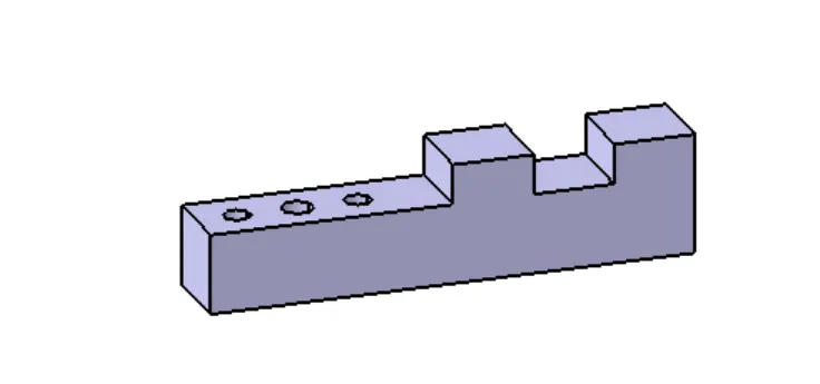
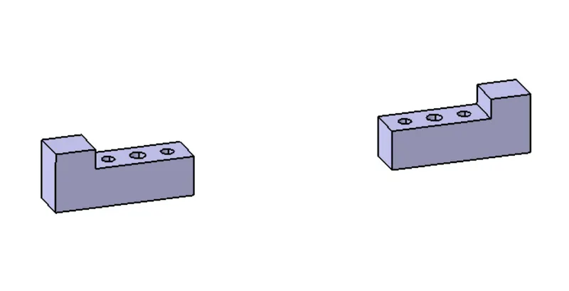
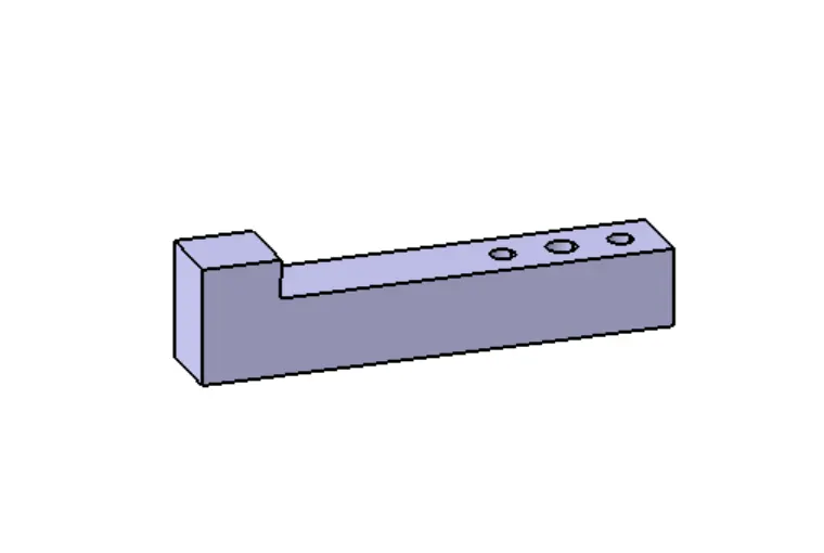
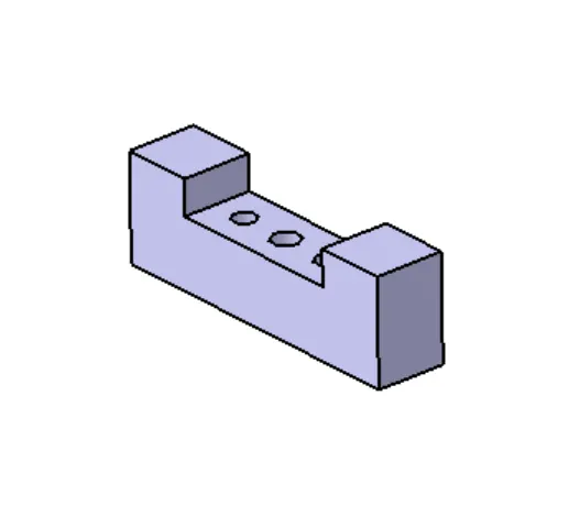
- Resting Mylar: Same as in rest unit, it is used to hold the component in place and the holding force is kept in mind while designing.
- Clamping Mylar: the clamp holds the component from above and is placed directly above it. The clamping force is determined by the outreach of the clamp mylar. It is calculated by calculating the horizontal distance between the center of the finger touching the car panel and the center of the rotating axis of the span arm.
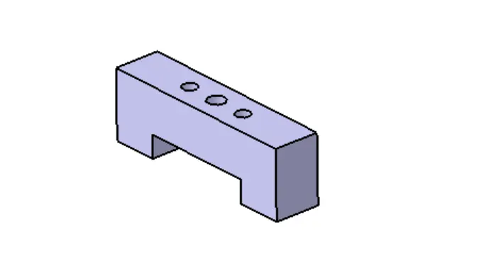
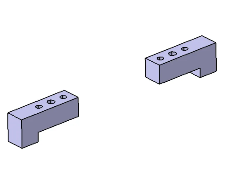
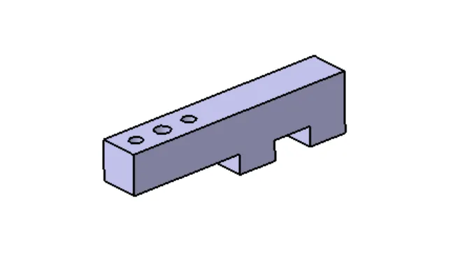
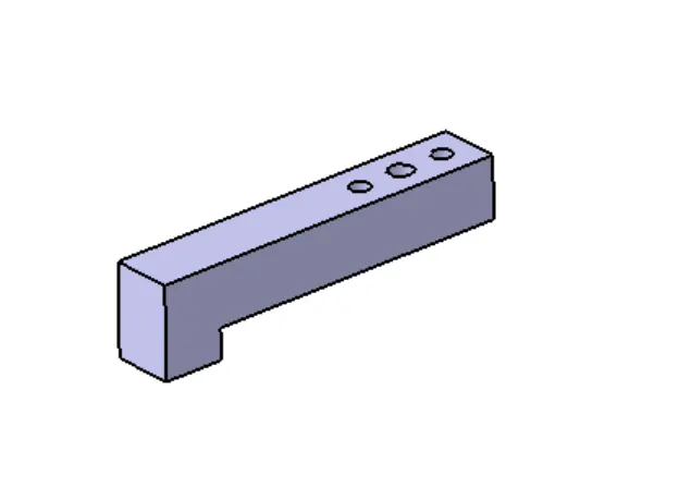
- Blade: Used to attach the resting mylar to the riser. As well as support the cylinder. It has a pivot hole to attach clamp arm. Stopper is mounted on the blade.
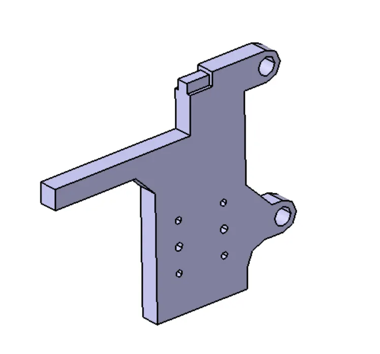
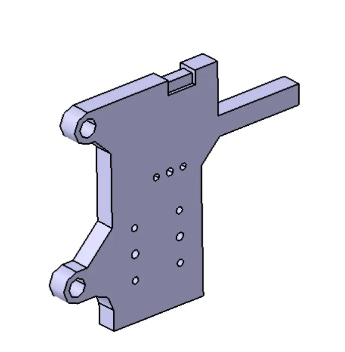
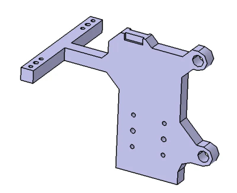
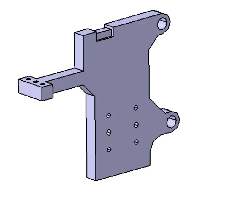
- Stopper: Stopper is used to stop the clamp arm at a position desired. It is mounted on the blade.
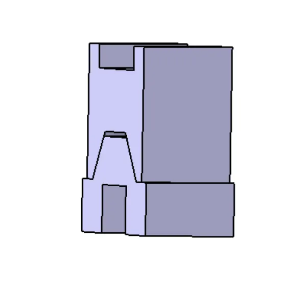
- Clamp Arm: Clamp arm is attached to the clamping mylar and is used to lift the clamping mylar with the help of cylinder. It has a pivot point with the blade.
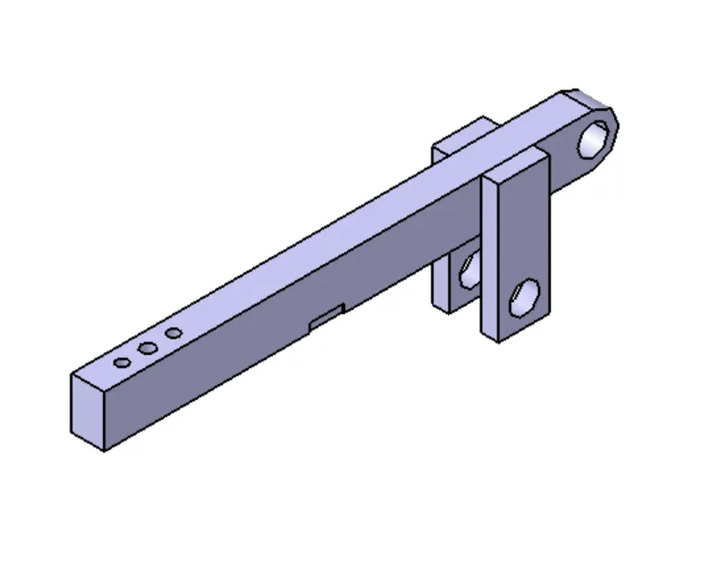
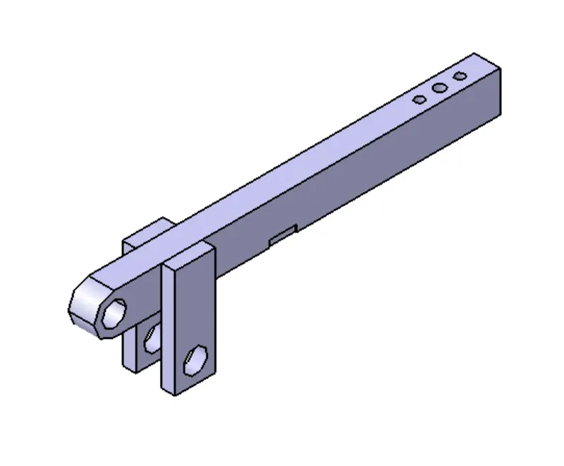
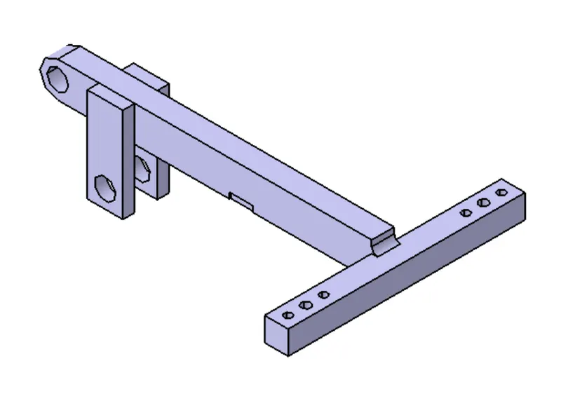
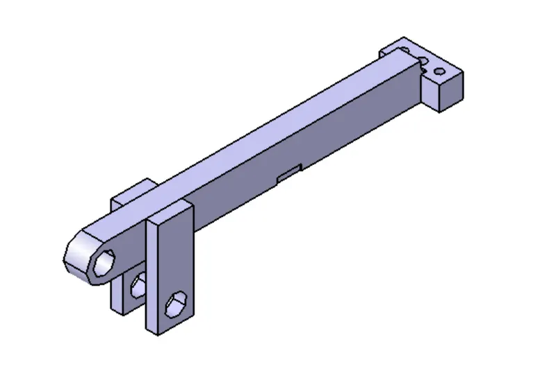
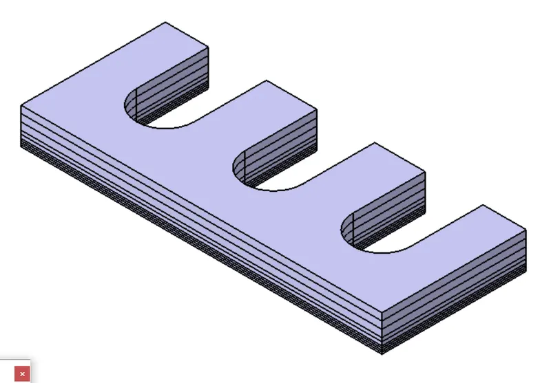
- Shims: Used to compensate for the stack up tolerances and is usually of an overall thickness of 5mm.
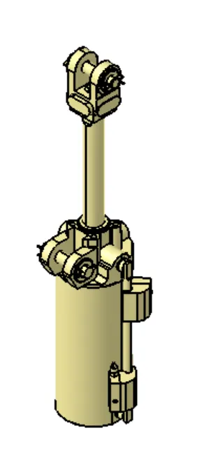
- Cylinder: It is a bought-out part and the span arm is attached to the cylinder which is connected to the clamping arm.
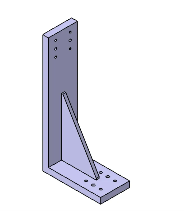
- Riser: Is the attached to the base plate and all the other parts are mounted on it.
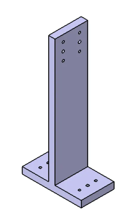
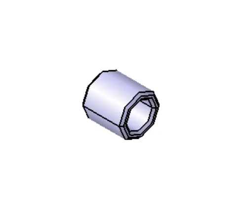
- Bush: It is used to reduce friction during motion of the swivel cylinder and for better contact.
Clamp-Pin Unit:
It consists of all the parts mentioned in the clamp unit. In addition, there are following parts to it,
- Pin: It is the locating pin, which can be a round or diamond pic depending on the need. It is used to keep the panel steady, so that is does not move which different process are carried out on the panel.
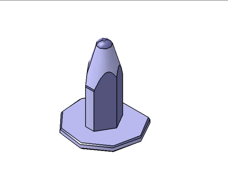
- Retainer: It is used to provide a two-way shim for adjusting the pin location which might change depending on the stack up tolerances.
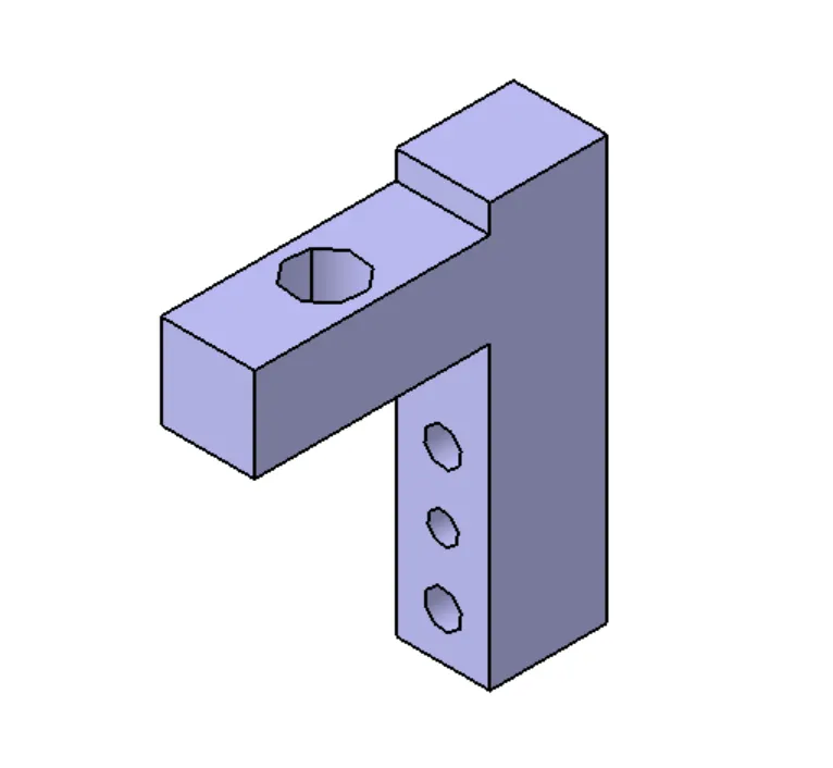
- Arm: It is used to connect the pin unit to the clamp unit. One end of arm is attached to L-block and the other end is attached to the blade.
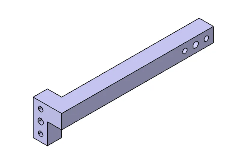
Swivel Clamp-Pin Unit:
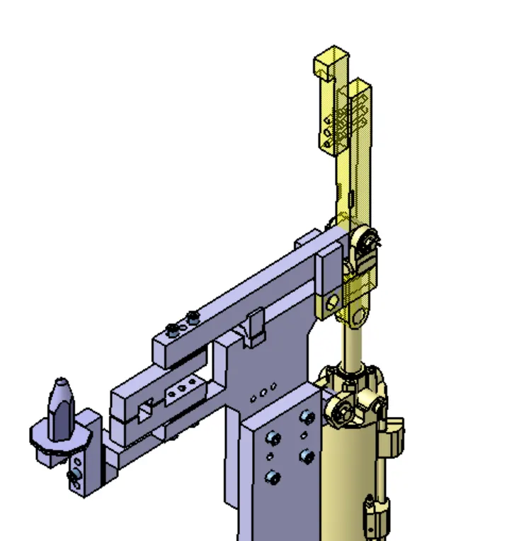
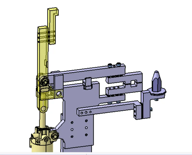
Swivel Clamp Unit 1:
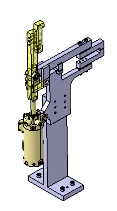
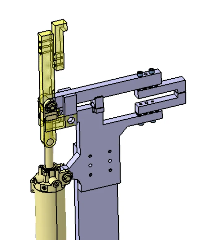
Swivel Clamp Unit 2:
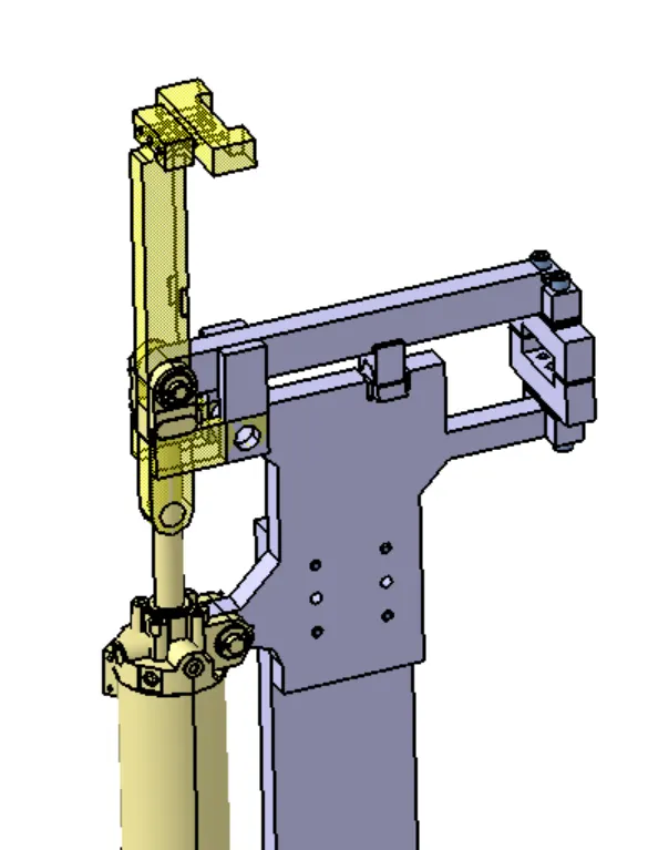
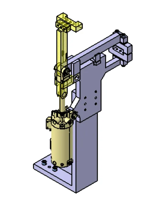
Swivel Clamp Unit 3:
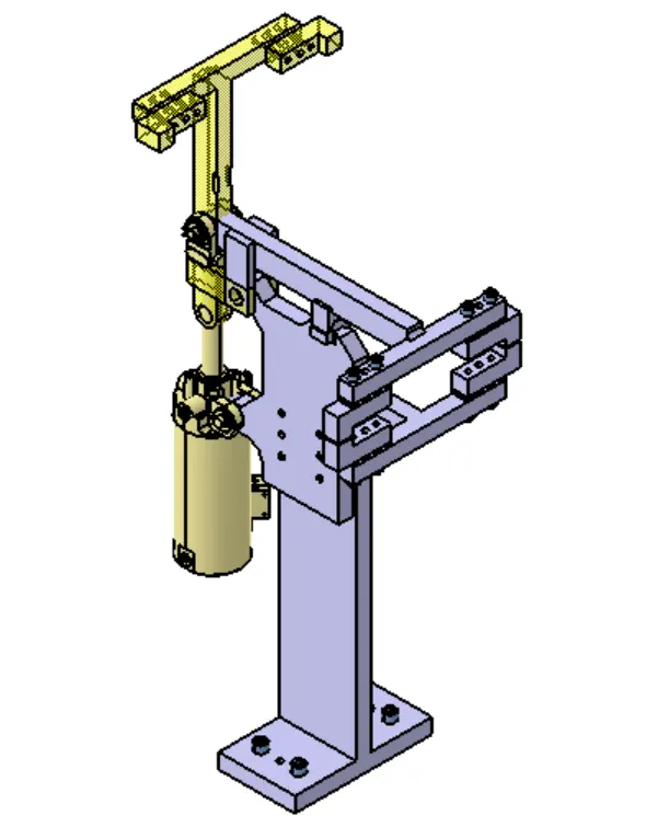
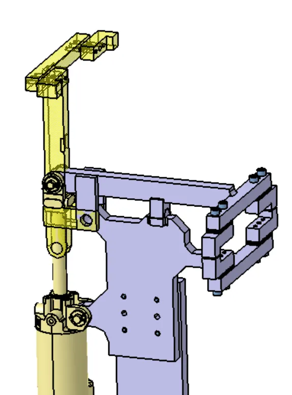
Assembly:
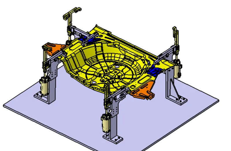
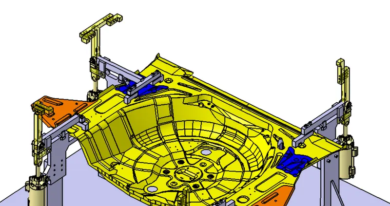
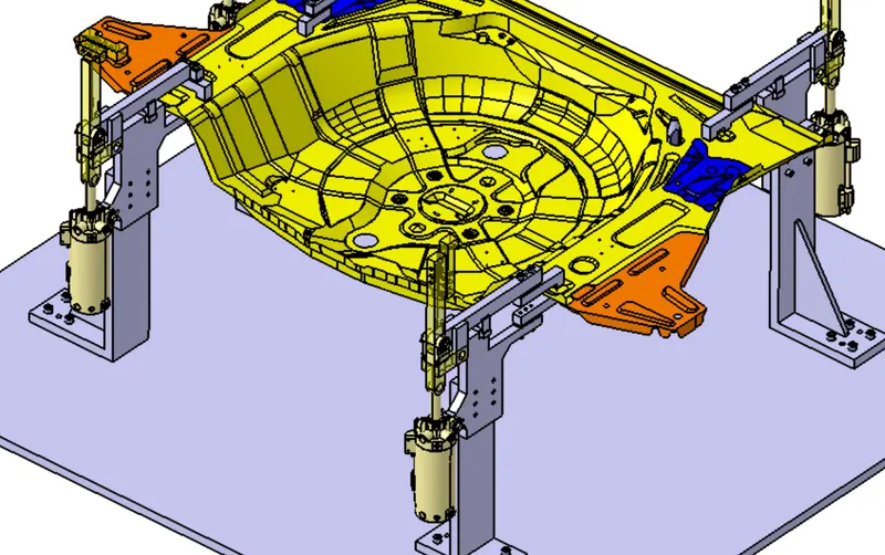
Conclusion: Thus, 3 Swivel Clamp Units with one Clamp-Pin is designed as mentioned.