CHT Analysis on a Graphics card using Fluent
OBJECTIVE:
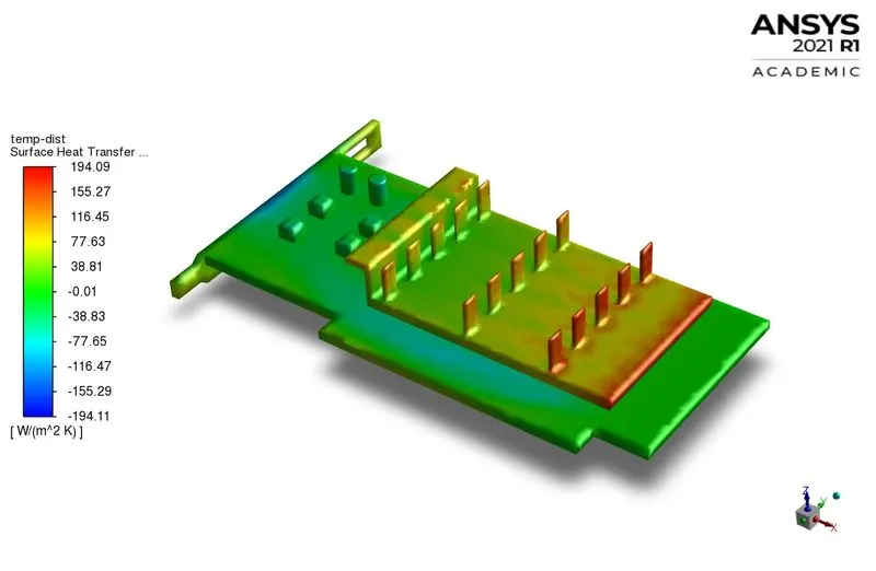
The aim of this challenge is to simulate Conjugate Heat Transfer (CHT) in a Graphics Card using Ansys Fluent. The temperature distribution is to be obtained on the surface of the Graphics Card. The Surface Heat Transfer Coefficient (HTC) is to be obtained on the surface of the fins and the GPU of the Graphics Card.
CONJUGATE HEAT TRANSFER [CHT]:
Modes of Heat Transfer:
i) Conduction: Conduction is the mode of heat transfer that occurs from a more energetic particle to the adjacent less energetic particle and it takes place in a stationary medium. It is the most predominant mode of heat transfer in solids. It can occur in liquids and gases as well but with relatively diminishing efficiencies. In solids, conduction takes place through the movement of free electrons and Lattice vibrations.
ii) Convection: Convection is the mode of heat transfer between a solid surface and the adjacent fluid that is in motion. It involves the combined effects of conduction and fluid motion. Convection may be Free convection, Forced convection and it may occur with phase change like Boiling and Condensation. The aim of the convection study is to calculate the Heat transfer coefficient (HTC).
iii) Radiation: Radiation is the mode of heat transfer that takes place through Electromagnetic Waves [EM Waves]. This mode of heat transfer is the fastest and it does not require any medium for the propagation. Usually, at low temperatures [room temperatures], Conduction and Convection dominate over Radiation and hence effects of radiation would be neglected.
Conjugate Heat Transfer:
Conjugate Heat Transfer (CHT) is a class of simulation that is used to model heat transfer which occurs simultaneously within and between solid and fluid regions. The exchange of thermal energy takes place at the solid-fluid interface. The predominant mode of heat transfer in fluids is convection and in that of solids is conduction. CHT is performed when the user is interested in capturing the temperature distribution from the solid to liquid region. Examples include simulation of heat transfer in the Engine from the Engine block to the flowing coolant, etc. Different governing equations are solved in the solid domain and the liquid domain simultaneously and the temperature is estimated at the interface.
Equations solved in the solid domain:
Steady state heat conduction equation:
`Cunderset(p)()*rho(delT)/(delt) = nabla(knablaT) + Sunderset(h)()`
Equations solved in the fluid domain:
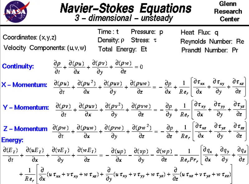
Navier Stokes Equations:
CASE SETUP IN ANSYS FLUENT:
I) Introduction:
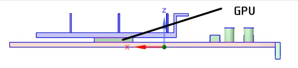
The physical model of the problem is as follows: A graphics card is kept inside an enclosure with moving air. The graphic card is made of multiple solid components that are defined in the next section. The heat transfer occurs as follows: The GPU of the graphic card generates heat. The GPU is in contact with the PCB and the heat sink. The PCB is of FR-4 material which is a composite material composed of woven fiberglass cloth with an epoxy resin binder that is a thermal resistor. Hence it does not conduct heat significantly. The heat is conducted to the heat sink. The fins of the heat sink increase the effective area of convective heat transfer. Forced convection occurs from the fins to the fluid. The HTC is determined wrt for different magnitudes of velocity.
It is expected that with an increase in the magnitude of velocity, the HTC must increase and the temperature distribution must become more localized. Three cases involving different air velocities are simulated:
Case #1: Air velocity of 1 m/s.
Case #2: Air velocity of 3 m/s
Case #3: Air velocity of 5 m/s
II) Geometry:
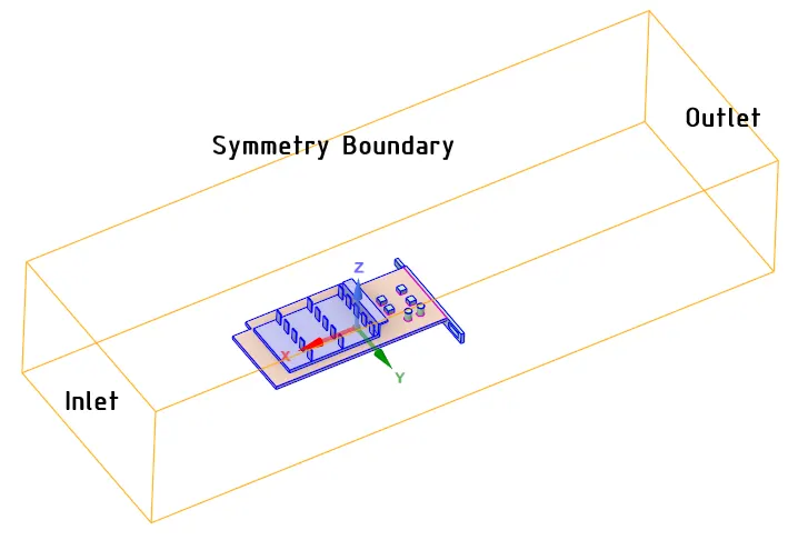
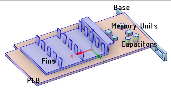
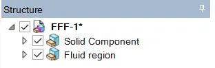
The physical model is shown below. The graphics card is a made-up CAD model that is imported to Spaceclaim in the .stl format. This made-up model contains the major components of a real graphics card- GPU, Fins, PCB, Memory Units, and Capacitors. The dimensions of the enclosure are (191 X 65 X 40.5) mm. The solid regions and the fluid regions are kept as separate components in Spaceclaim (shown below) so that Fluent does not consider all regions as a fluid region by default. The final topology is 'shared' using the Workbench --> Share option in order to create a Conformal mesh.
III) Meshing:
The base element size is given as 3 mm. Named selections are created on the enclosure and to different components of the Graphic card to specify the material. The named selection are as follows: Inlet, Symmetry and, Outlet on the enclosure; GPU, Fins, Base, Capacitor, Memory unit, and PCB on the graphic card.
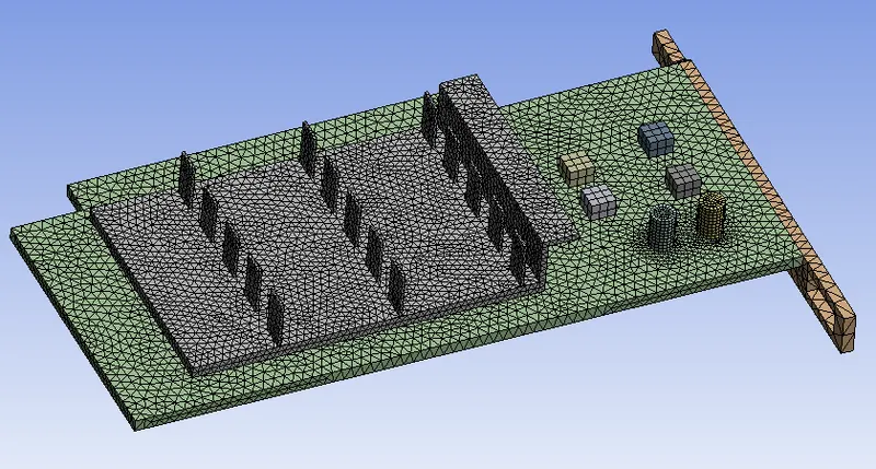
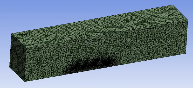
Only the heat transfer at the macroscopic level is of interest. Hence the mesh is refined based on the total cell count and the ability to capture curvature. The temperature distribution and the HTC is to be determined on the surface of the graphics card. The GPU (heat source) is connected by both the PCB and the heat sink. Hence, these three components are refined to the maximum possible extent keeping the mesh of the enclosure relatively courser.
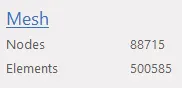
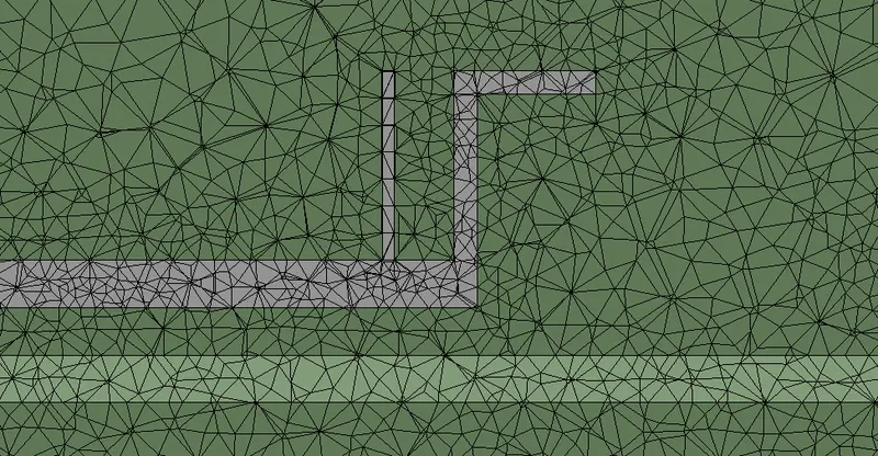
Mesh Body sizing is specified on the GPU, Fins, and PCB. The mesh sizes are shown below. The generated mesh is checked for conformity by creating a section plane. Shown below are the images depicting the mesh on the Graphics card and the conformity of the mesh between the solid and the fluid regions respectively.

IV) Fluent:
- A pressure-based, steady-state solver is used.
- The energy equation is switched on.
- The Standard `k-epsilon` turbulence model is selected.
- The solid zones and fluid zones are defined in 'cell zones' under the Physics tab.
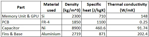
- Materials are chosen in the 'Create/Edit Material'. The materials are then specified to the different components of the Graphics card. The table of materials for the corresponding solid parts are shown below. The material properties are constant and do not change under any condition.
- Since there is an enclosure, each zone in this CHT simulation has a two-sided wall meaning the mesh is present on both sides of the walls of any zone inside the enclosure. Hence, no specific convection/ conduction boundary condition needs to be specified. The heat source is specified on the GPU. The velocity at the Inlet of the enclosure is specified according to Case #1, #2, or #3. The outlet boundary is to pressure BC of 1 atm.
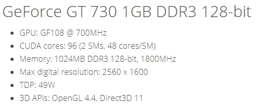
- The volume of the GPU is 64 mm^3. Considering a standard Nvidia GT 730 graphics card, its Thermal Design Point [TDP] i.e, the amount of heat that is generated by the GPU which is to be dissipated by the heat sink is 49 Watts. Fluent requires the heat generation term to be entered as a source term in W/m^3. This source term is specified on the GPU under 'Cell zones'. The Heat generation rate is calculated as = `(49 )/(64e-9) = 7.65 e+8 W/m^3`
- The solution scheme is a 'Coupled' pressure velocity scheme.
- The solution is initialized using the Hybrid solver.
- The temperature contours, the temperature on GPU and Fins, Wall HTC on the surface of fins and GPU, are all set up under the 'results' tab.
- The time scale is set to 1 and the number of iterations is set to 400. The case is run.
RESULTS AND POST-PROCESSING:
I) Convergence:
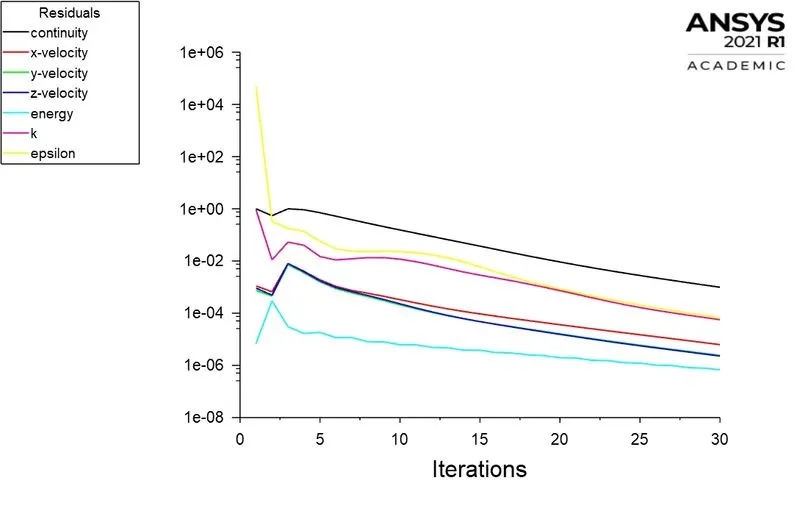
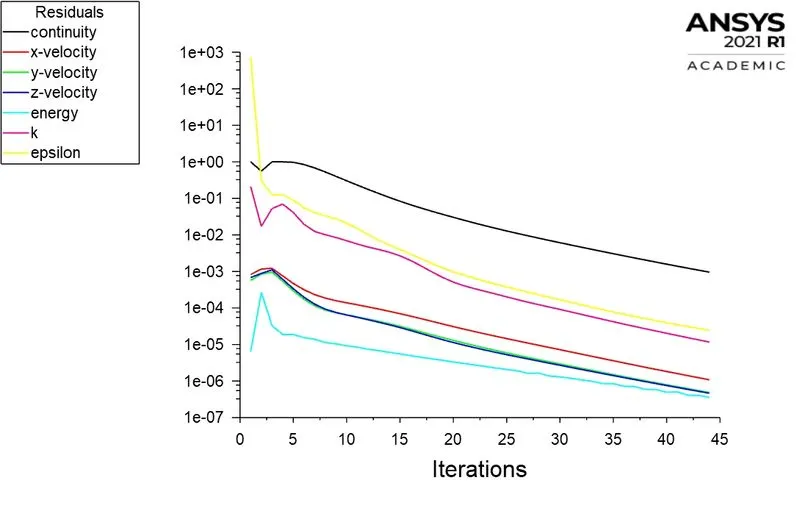
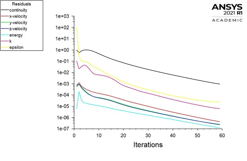
Shown below are the residual plots for all the cases. The simulation was set to run for 300 iterations but the solution attains convergence before. The plots are shown below.
Case#1:
Case#2:
Case#3:
II) Velocity and HTC Contour:
- The velocity contour is an important output parameter in convection heat transfer and is shown below for Case #3.
- Low-velocity zones are formed between the fins and close to the trailing edge of the graphics card, the magnitude of velocity increases.
- It is later shown from the vector plots that these low-velocity zones are local recirculation zones.
- Since Nusselt Number is a function of Reynolds number and Prandtl number, the magnitude of velocity directly affects convective heat transfer.
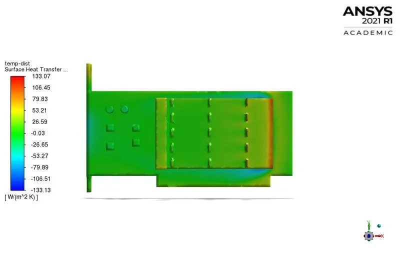
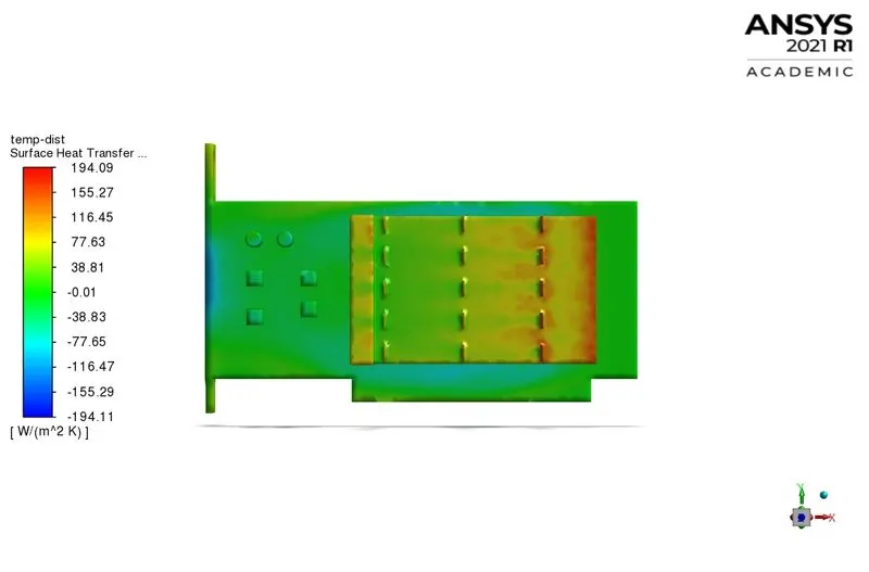
- From the surface HTC shown below for case #3, it is observed that the HTC is maximum for the fins at the leading edge of the graphic card and it decreases subsequently for the next layers of fins.
- Similar velocity and HTC contours are obtained in other cases. (not shown)

III) Total Temperature and HTC Contour:
Case#1:
 Case#2:
 Case#3:
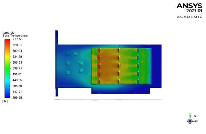
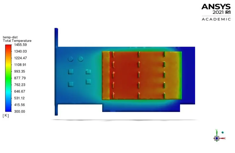
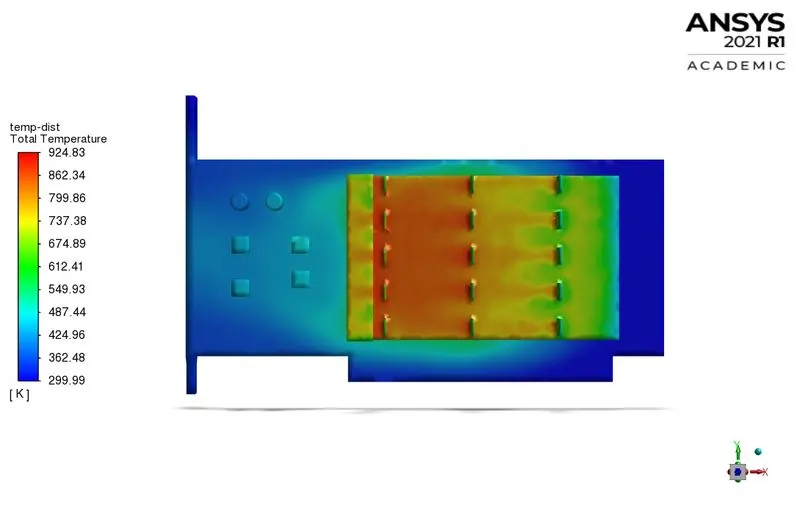
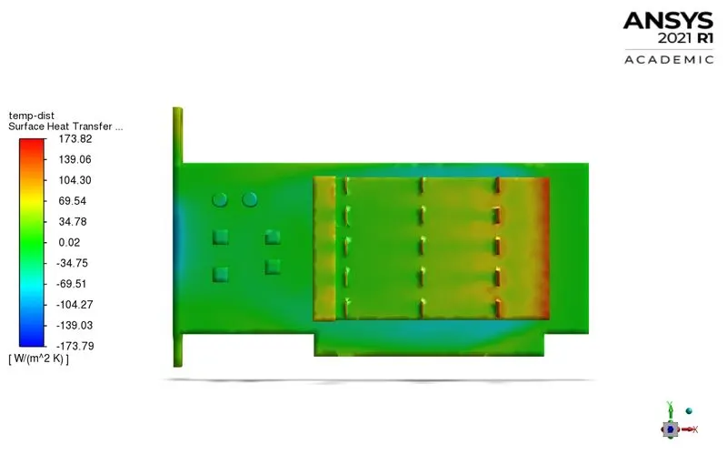
- The plots on the LHS depict the total temperature contour and those on the RHS depict the surface HTC contour. The total temperature rather than static temperature is considered to account for the changes in temperature due to the fluid flow.
- In Case #1, the heat sink shows high temperatures. This is because the PCB does not conduct and the fins (aluminum) have high thermal conductivity. The HTC is high for the first layer of fins close to the leading edge of the graphics card and decreases subsequently for the next layers. Hence the heat transfer decreases from the second and the third layer of fins. This region between the second and the third layer of fins forms a thermal hotspot and must be taken into account during the design of the fins. The temperature at the hotspot must not get close to the melting point temperature of the material.
- This thermal hotspot becomes more local to the region between the second and the third layer of fins with increasing magnitude of velocity at the inlet as the Convective HT becomes more effective with an increase in velocity.
IV) Variation of HTC and Max temperature wrt velocity:
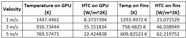
- With an increase in velocity, the HTC increases, and the area-weighted average temperature of the GPU and the fins decreases as expected.
V) Recirculation region:
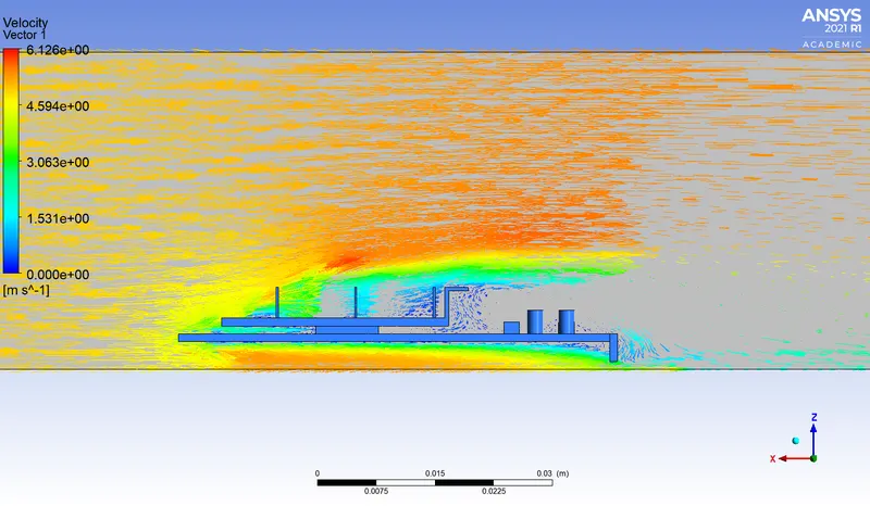
- This is a vector plot colored by velocity on a plane perpendicular to the flow for Case #3.
- It is observed that there are local regions in flow between the fins where there are no vectors visible. At these locations, the vectors are very small in magnitude because of the formation of local recirculation zones. At these locations, there is a drop in velocity and an increase in pressure.
- It is because of the formation of these recirculation regions, that the HTC drops between the layers of fins that eventually leads to the formation of a thermal hotspot.
- Beyond the fins, there exists a bigger, visible recirculation region.
CONCLUSION:
A Steady-state Conjugate Heat Transfer simulation is performed on a Graphics Card inside an enclosure subjected to a moving fluid. These cases are run at different magnitudes of fluid velocity. The temperature distribution, the wall Heat Transfer Coefficient (HTC) on the fins of the heat sink, and the GPU are determined. With increasing velocity, the area-averaged temperature on the GPU and the heat sink decrease, and the HTC increases. A thermal hotspot is identified in the heat sink whose max temperature must be considered during the design.