Week 6 - CHT Analysis on a Graphics card
CONJUGATE HEAT TRANSFER ANALYSIS ON A GRAPHIC CARD
AIM : To perform a steady-state simulation on a graphics card, and observe the thermal effects of air velocity over the graphics card geometry
INTRODUCTION:
Conjugate heat transfer (CHT) allows the simulation of the heat transfer between Solids and fluid domains by exchanging thermal energy at the interfaces between them. Conjugate heat transfer (CHT) analysis can accurately predict heat transfer by simultaneous solving all the relevant solid and flow field heat transfer processes.
- Typical applications of this analysis type are
- the simulation of Heat exchangers
- Cooling of electronic equipment
- General-purpose cooling Heating systems
Conjugate heat transfer corresponds with the combination of heat transfer in solids and heat transfer in fluids. In solids, conduction often dominates whereas, in fluids, convection usually dominates. Efficiently combining heat transfer in fluids and solids is the key to designing effective coolers, heaters, or heat exchangers. Forced convection is the most common way to achieve a high heat transfer rate. In some applications, the performances are further improved by combining convection with phase change.
The CHT approach has an advantage over FE thermal Analysis in that wall heat transfer coefficients and their local variations on surfaces are directly calculated within the model rather than based on simplified empirical calculations. The CHT approach, therefore, has benefits for those applications where heat transfer is either non-uniform or difficult to calculate empirically. Typical design problems involve the determination of: Overall heat transfer coefficient, e.g. for a car radiator. The highest (or lowest) temperature in a system, e.g. in a gas turbine, chemical reaction vessels, food ovens. Temperature distribution (related to thermal stress), e.g. in the walls of a spacecraft. Temperature response in time-dependent heating/cooling problems, e.g. engine cooling, or how fast does a car heat up in the sun and how is it affected by the shape of the windshield?
GRAPHIC CARD:
Graphics Card is one of the most important components of a gaming PC or a professional high-performance PC. It packs a huge amount of power and has different components that work altogether for graphics processing. The Graphics Card is responsible for rendering an image to your monitor, it does this by converting data into a signal your monitor can understand. The better your graphics card the better, and smoother an image can be produced. This is naturally very important for gamers and video editors
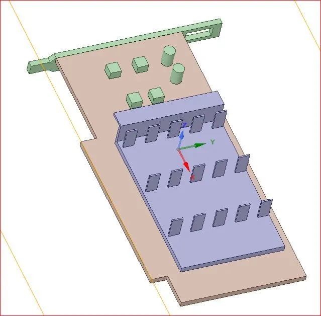
The main components of graphic card are
- Processor
- Fins
- Base
PROCESSOR:
A GPU(graphics processing unit) is designed specifically for performing the complex mathematical and geometric calculations that are necessary for graphics rendering. Some of the fastest GPUs have more transistors than the average CPU. A GPU produces a lot of heat, so it is usually located under a heat sink or a fan.
FINS
Fins act as a passive heat exchanger that transfers the heat generated by an electronic or a mechanical device to a fluid medium, often air or a liquid coolant, where it is dissipated away from the device, thereby allowing regulation of the device temperature at optimal levels. Aluminium alloys are the most common heat sink material. This is because of aluminium cost lesser than copper.
here also we have used aluminium as a fin material. Some heat sink are combination of aluminium fins with copper base.
BASE :
The base is defined as a part on which various component is attached. The base is the part where processor, fins and other connections are connected to it.
He have used ABS as base material the material which is at base should not be a good conductor of heat so we have employed a ABS with thermal conductivity of 0.25w/mk
The graphic card that is taken to analyse the conjugate heat transfer
ASSUMPTIONS:
- The fluid medium is considered to be air with a velocity of 3m/s, 4m/s, 5m/s .
- The processor is considered of Silicon, fins of aluminium and base are of ABS
- The thermal design power(TDP) of the processor is assumed to be 10W. SO the total heat generated is calculated by using this.
GEOMETRY:
- The geometry of model consists of base , processor and fin assembled together.
- And an enclosure is built around it for flow analysis
- The given geometry is imported into ansys spaceclaim
- Check for any extra edges and enable the share topology between the parts so that conformal mesh is generated
- Check for interference if any then resolve those before moving to mesh
- then go the workbench tool in spaceclaim and using share option enable share topology to have an conformal mesh in mesh setup
MESH SETUP:
Now open mesh setup by double clicking on it
- First create a named selection of inlet and outlet if any.
- then generate the baseline mesh
- then check for mesh conformity, if mesh is fine then check for mesh metrics and refinement
- if mesh is not conformal then go to space claim again and enable share topology
BASELINE MESH FIGURE AND MESH DETAILS
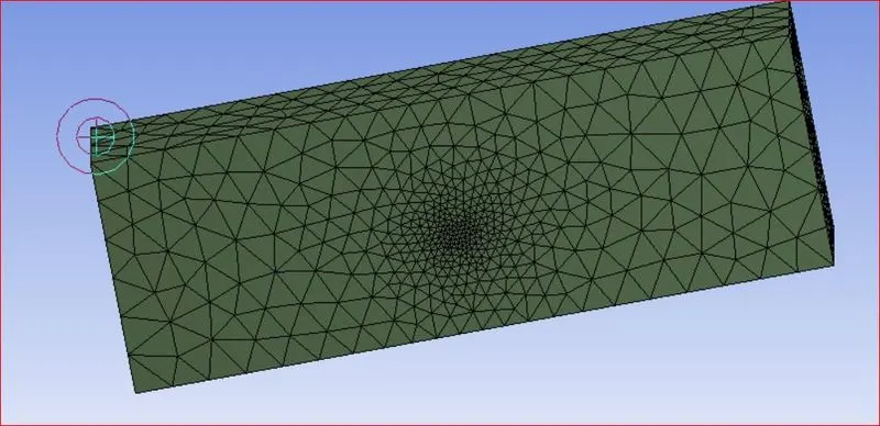
|
BASELINE MESH |
|
|
No of nodes |
11304 |
|
No of Elements |
52991 |
MESH REFINEMENT:
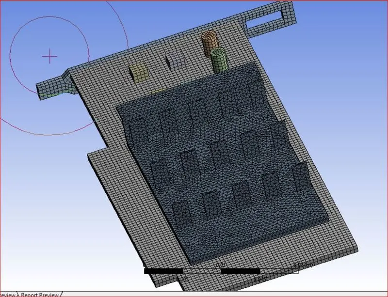
with baseline mesh the results obtained are may not be correct there may be a huge variation also sometimes so that refinement of mesh has to be done for a very good results
Refinement of meshing is done for the baseline mesh
first method is chosen for mesh set up by right clicking on mesh and then add insert method
then again further refinement is done by using body sizing for processor and fins and base of the graphic card by choosing the mesh size of 0.1mm
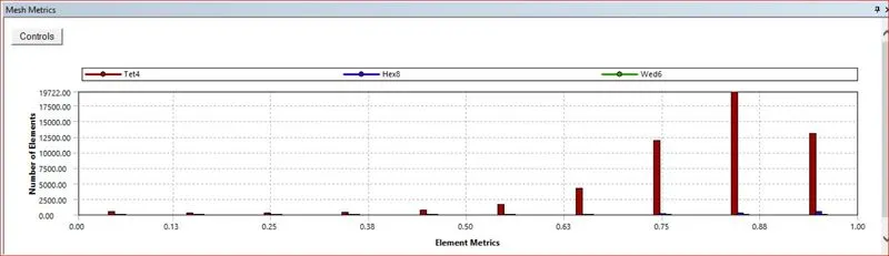
now check of the element metrics skewness if it is acceptable level then meshing is closed and proceed to fluent
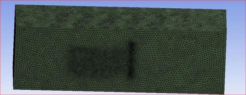
MESH DETAILS:
| REFINED MESH DETAILS | |
| No of nodes | 210997 |
| No of Elements | 1100393 |
ELEMENT METRICS:
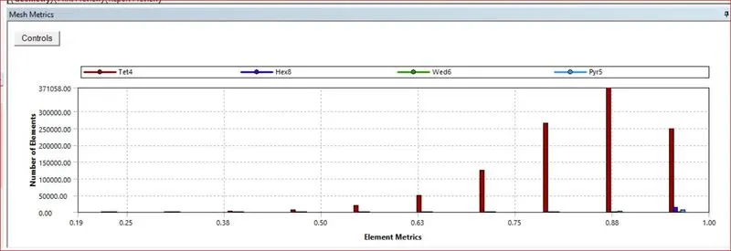
from the mesh metrics the refined mesh is good and we can proceed for fluent setup.
FLUENT SET-UP:
GENERAL:
Time: steady
Solver: pressure-based
Viscous model: K-Epsilon Realizable model is selected, as it is faster to converge.
ADD-MATERIAL:
- Fins : solid - Aluminium
Standard aluminium is available in Fluent database.
Density = 2719 Kg/m^3
Heat capacity = 871 J/KgK
Thermal conductivity = 202.4 W/mK - Processer : solid - Silicon
Since the silicon is not available in Fluent's solid database, we need to define it
Density = 2330 Kg/m^3
Heat capacity = 705 J/KgK
Thermal conductivity = 148 W/mK - PCB : solid - ABS
Since the ABS is not available in Fluent's solid database, we need to define it
Density = 1050 Kg/m^3
Heat capacity = 1390 J/KgK
Thermal conductivity = 0.25 W/mK
In material, we have created all three solid material, for our model. After creating material, we have assigned materials to their zones. Various zones created for processor, fins, and base. And one fluid zone is created for the domain, with material air, which will act as heat transfer source from fins to air. As, we have one energy source as the processor, which will generate a large amount of energy as heat, that's why heat source is created in the processor zone, with a constant value.
let us assume that the processor is generating heat of 10W
then we should add a energy source to processor in cell zone condition
energy source Qv = W/V = 10/(64*10^-9)=1.56*10^8 w/m^3
CELL_ZONE_CONDITIONS
Defining of solid and and fluid zones in cell zone condition correctly is very important is any mistake done then the total result is going to be a garbage value
Enclosure as Fluid : Air Fluid Temperature : 300K
Fins as Solid: aluminium (as mostly used)
Processor as Solid : Silica (one source is added to processor Energy : 1.56e+8 W/m^3 )
Base as Solid : ABS
Energy : 1.56e+8 W/m^3
BOUNDARY CONDITIONS :
Inlet : Velocity : 3m/s,4m/s and 5m/s
Outlet: Pressure : 0 Pa (Gauge Pressure)
Walls of Enclosure: Symmetry
Then after imposing boundary conditions the solution is initialized
Then moved to CFD-POST and the contours required are plotted
RUN CALCULATION:
Now solution is made to run till the residuals are converged
The convergence is checked upto 1e-5 to avoid error value in output
Here the solution is run under three different velocity ( v=3m/s, v=4m/s, v=5m/s)of air inlet and results are discussed
No of iterations = enter required no of iterations to be done
then calcuation is done
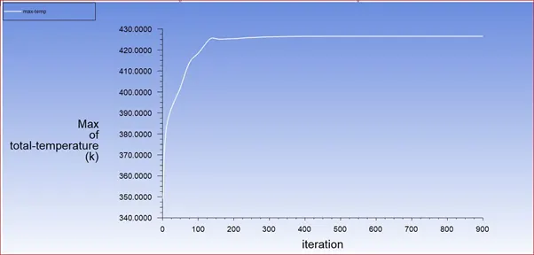
CASE1: with air inlet velocity V = 3m/s
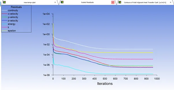
from the residuals plot it is observed that the residuals are converged at 600 iterations
CONTOURS:
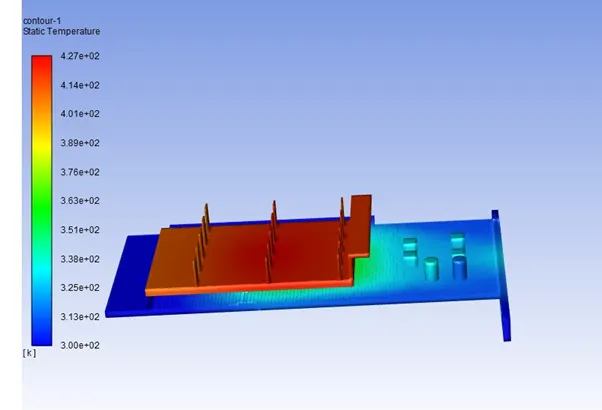
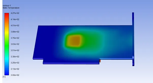
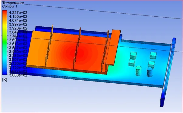
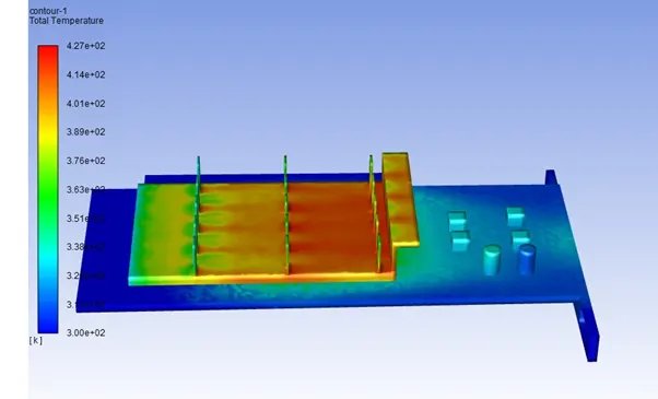
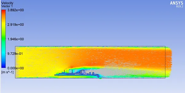
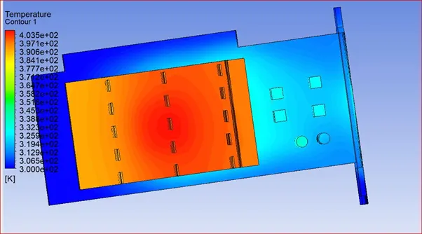
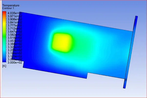
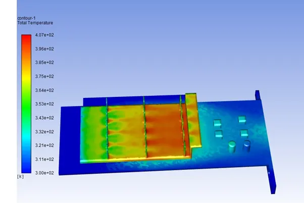
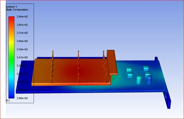
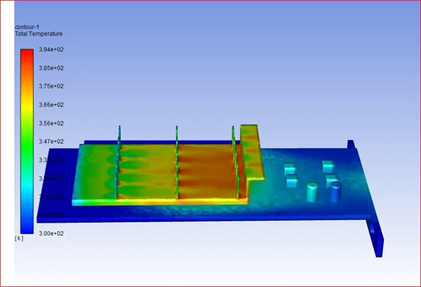
- Here we can observe that front portion of fins is more cooled then rear portion.
- Stagnation of air at the rear portion of fins, and so the temperature is high in that area, which can more clearly observed.
- Also we can see that at the lower portion of fins are hot, and as we go from lower to upper portion, it can be observed that heat transferred more at the top of the fins.
- As air can easily passes on the top of the fins, more it cools, where it is difficult to reach to bottom fast for the air, so it is high in temperature.
- Also rear portion of fin, where high temperature can be observed as it collides to the walls of fins, it cools and the rest area remains hotter than that.
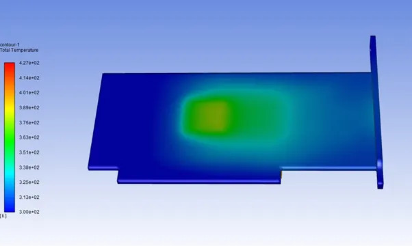
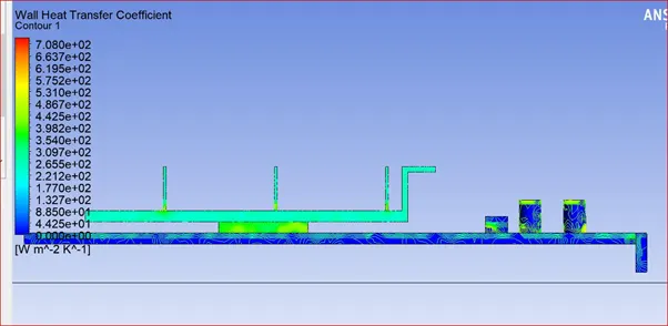
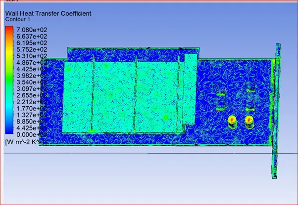
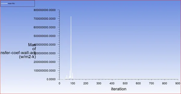
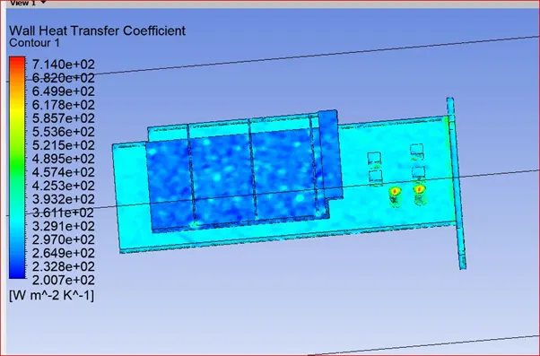
- From above image we can see more clearly that lowest heat transfer coefficient measured at rear portion of the fins.
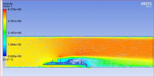
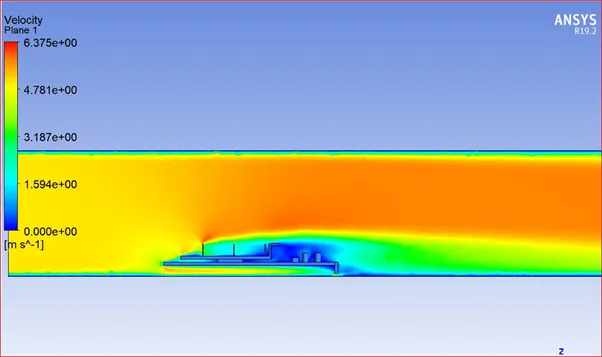
- Which is due to low velocity behind the fins or due to recirculation of air
- When velocity decreases, Reynolds number decreases, and due to that there can be lower heat transfer coefficient.
- Due to fine mesh it is observed very clearly from above image.
- Lower the velocity; lower the rate of heat transfer.
PLOTS:
CASE2: with air inlet velocity V = 4m/s
RESIDUALS:
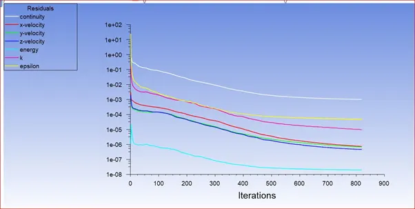
from residuals it is observed that the solution is converged at 700 iterations
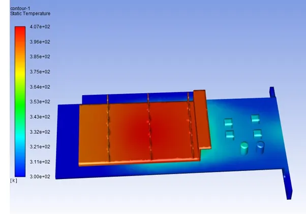
CONTOURS:
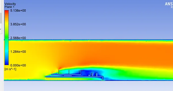
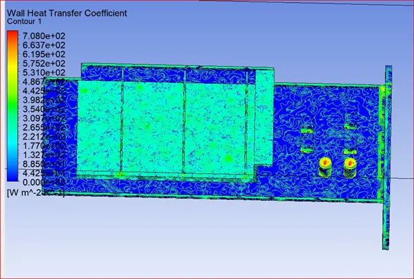
PLOTS:
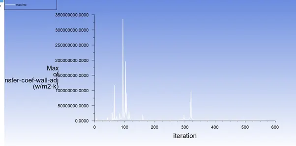
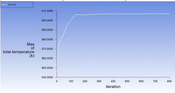
CASE3: with air inlet velocity V = 5m/s
RESIDUALS:
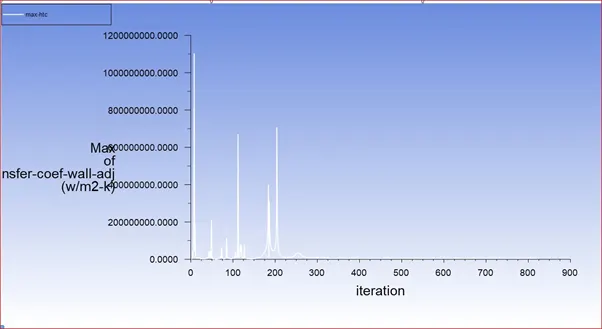
from the residuals it is clear that the residuals are converged at 800iteration
CONTOURS:
PLOTS:
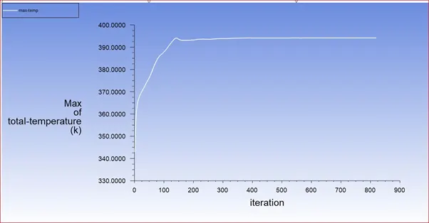
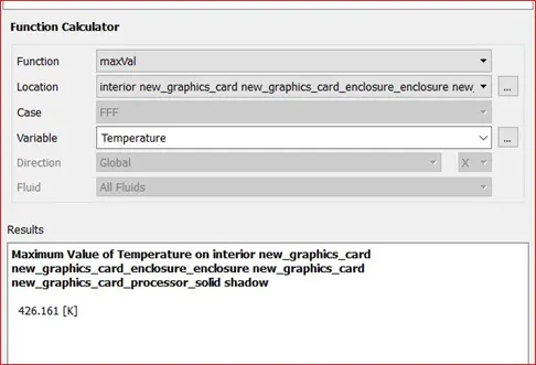
MAX VALUES OF TEMP OF PROCESSOR AND HTC IN ALL THE CASES:
CASE1: V= 3m/s
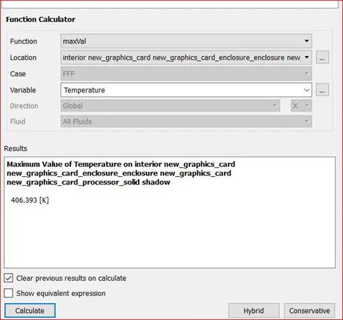
CASE 2: V= 4m/s
CASE 3: V= 5m/s
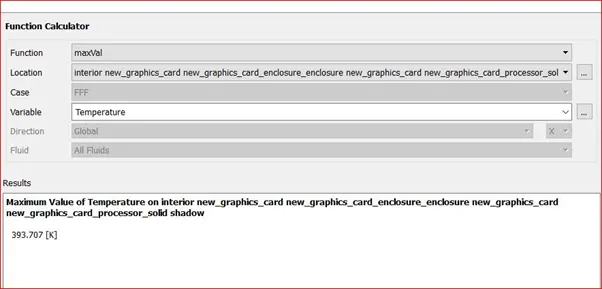
The value of HTC(h w/m2k) is calculated from the formula
Q = hA(Tmax-Tref )
h = heat transfer co efficient w/m2k = value to be calculated
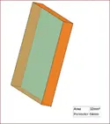
A = exposed area for convective heat transfer m2 = 4*(8mm*1mm )= 32 mm2 =32*10-6 m2
Tmax-Tref = temp difference of temp of processor and temp of surroundings K = varies with velocity
Q = heat generation of processor W = assumed to be 10w
CASE1 :
At v=3m/s
Tmax-Tref = temp difference of temp of processor and temp of surroundings = 426.161-300
10 = h* 32*10-6*(426.161-300)
h = 2476.99 w/m2k
CASE2 :
At v=4m/s
Tmax-Tref = temp difference of temp of processor and temp of surroundings = 406.33-300
10 = h* 32*10-6*(406.33-300)
h = 2938 w/m2k
CASE3 :
At v=5m/s
Tmax-Tref = temp difference of temp of processor and temp of surroundings = 393.707-300
10 = h* 32*10-6*(393.707-300)
h = 3334.86 w/m2k
POTENTIAL HOTSPOTS ON THE MODEL OF GRAPHIC CARD:
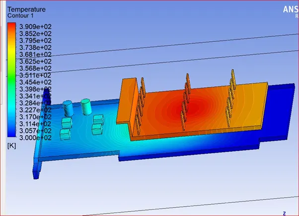
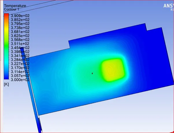
The potential hotspots on the model of the graphic card is the area above and below the processor and the processor as it is the only energy generating source.
Observing the heat transfer coefficient plots and temperature plots under different inlet velocities above, two potential hotspots can be identified.
The contours above display the HTC of the graphic card. The first location that will be discussed is the area just beyond the processor, after the fluid flows over the processor. Upon observing the HTC contour of the case with a freestream velocity of 1 m/s, it can be seen that a low heat transfer coefficient is present in that area. A low heat transfer coefficient suggests that heat transfer is not taking place at a desirable rate in this area.
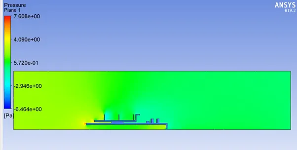
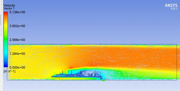
This is area is important, as the heat generated by the processor should be taken away by the air, and cool down. But, this is not the case, as the closed nature of the geometry, and the low velocity contribute the heat remaining in that area. Flow separation takes place after the fluid crosses the processor, creating a low pressure region in that area. The low pressure region influences the fluid flowing around it, and the fluid in and around that volume slows down. Since the velocity of the air is extremely low in this region for the first case, the heat transfer by convection reduces and it results the region begins to heating up.
This phenomenon can be seen to great effect in the contour plot for temperature. The high temperature present in this area can cause damage to the components present in its proximity. However, this effect reduces with an increase in the freestream velocity of air. The average high speed of the air is enough to offset the effects of the flow separated zone for two reasons. Since the speed of the air is high, the low pressure zone that has been created behind the processor is unable to exert enough force on the fluid flowing just at the boundary of the flow separated zone. Due to this, the flow separated region does not grow larger in size, and hence, the effect of the flow separated region reduces.
The second hotspot that is identified can be seen in the cases with higher velocity. The high velocity air upon impinging the surface of the processor, decrease in velocity creates a high pressure zone, due to the impact. The fluid present in this zone exert a force on the fluid surround this area, and the velocity of the fluid around the zone increases. A positive pressure gradient is created at the edges of the processor, and the fluid velocity increases. However, the impact of the fluid on the processor causes the velocity to decrease in this area, and the fluid is unable to immediately re-join the fluid flowing around it, as it does not possess the required energy. Since the velocity of the fluid has reduced, the heat transfer in this region reduces as well, creating a hotspot. The temperature contour plots displayed below show both of these hotspots.
CONCLUSIONS FROM RESULTS:
|
|
MAX TEMP |
MAX HTC |
|
CASE1(v=3m/s) |
426.161K |
2476.99 w/m2k |
|
CASE2(v=4m/s) |
406.33K |
2938 w/m2k |
|
CASE3(v=5m/s) |
393.707K |
3334.86 w/m2k |
Observing the results obtained after simulating three different cases with different values of inlet velocity.
it can be concluded that the heat transfer coefficient increases with increase in freestream velocity.
The heat generated by the processor is taken away by the air flowing over it, and increasing the velocity will result in an increase in the heat transfer by convection. This ultimately results in a lower processor temperature.
it can be concluded that the velocity of air over the geometry has a profound impact on the temperature of the processor, and the body itself. A higher value of inlet air velocity will help maintain the health of the graphics card processor.
while a lower value of air velocity cannot prevent the processor from high temperature this results in damaging the components around its proximity.
Two main hotspots were observed after running the simulation, due to flow separation near the processor for the first case, and due to a high pressure zone caused by fluid(air) impingement on the processor body for the last two cases.
The heat transfer coefficient increases consequently then heat transfer will increase with an increase in freestream velocity of air inlet.