Week 6 - CHT Analysis on a Graphics card
AIM: Conjugate heat transfer on a graphic card
THEORY:
What is conjugate heat transfer?
- Conjugate heat transfer corresponds to the heat transfer in solids and fluids simulatenously. In solids conduction is more dominant whereas in fluids convection is more dominant.
What is a graphic card?
- Graphics card is a hardware which is used to increase the video memory of a computer, and make its display quality more high-definition. It makes the computer more powerful and gives it the capacity to do more high-level works.
What are the major components of the graphic card?
- There are three main components in a graphic card:
- Processor: The processor is the main unit of the graphic card which is also known as the graphic processing unit. The processor is a specialised unit which is designed to accelerate graphic rendering. They can process many piece of data simultaneously making them useful for machine learning, video editing and gaming applications. Processors are made using silicon or germanium.
- Fins: Fins are heat sinks that are using in a graphic card to remove excess heat from the processor. They are made using material that are capable of good conductors of heat like copper.
- PCB (Printed circuit boards): The PCB is the base of the graphic card where all the ports, processors etc are mounted. They are commonly made using fiberglass. Fiberglass is used to meet critical electrical, corrosion resistance, thermal conductivity, dimensional stability and dielectric properties critical to the performance of the final parts.
Which component is responsible for generating heat in the graphic card? Why?
- Heat is generated mainly by the processor. The processor is made using semiconductors. They have resistances within them. When the electricity flowing through the processor increases due to the resistance high heat is generated.
SOLVING AND MODELLING APPROACH:
- The model of graphic card will be uploaded to ANSYS fluent. In spaceclaim, the model will be oriented properly and it will be made sure that all the edges/faces that needs to be connected together are connected in order to create a conformal mesh.
- After that we will move to the meshing module and check whether the geometry has been meshed properly or not. We will name the components here so that it is easy for us to find the components while solving.
- We will use a k-omega model for our analysis. We will use a steady state solver. Since we need to calculate the heat transfer rate we need to make sure that we provide proper cell zone condition by differentiating fluid and solid boundaries.
- In the graphic card, different materials are used for different component which will be assigned to their respective components.
- Processor is the heat generating source here hence the processor will be treated as a heat source.
- After providing the boundary conditions, we will plot different contours to analyse the heat transfer taking place.
PRE-PROCESSING/ GEOMETRY CLEANUP:
- We will import the geometry in spaceclaim.
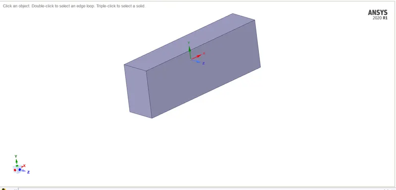
- We would need to change the default view of the entire geometry. We will use the move feature to rotate the geometry by 270 degrees.
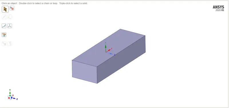

- Once the orientation has been completed, we will use the share feature to share all the faces within the geometry.
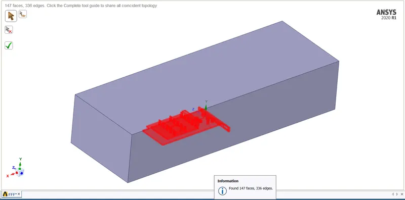
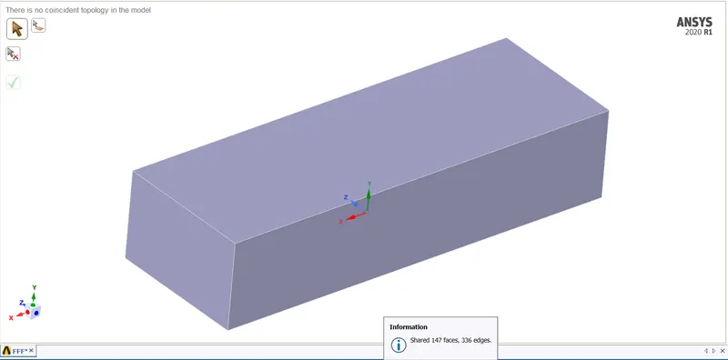
- Once the geometry has been shared, we will close spaceclaim and move to meshing.
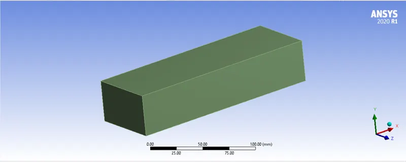
- Once we have loaded the model we can go forward and given names to different components of the body which will help in identifying the component while fluent.
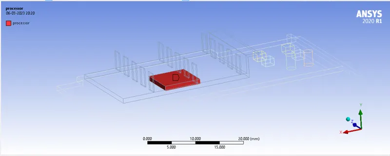
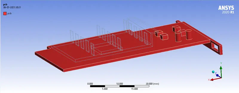
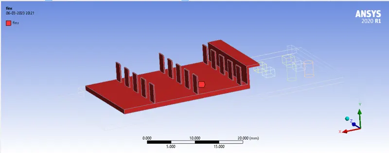
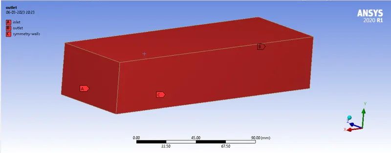
- First we will give coarse mesh throughout the model to evaluate the results. The mesh length to be given will 5mm.
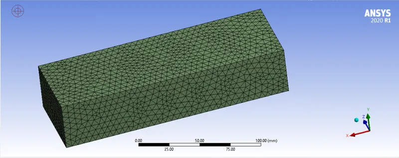
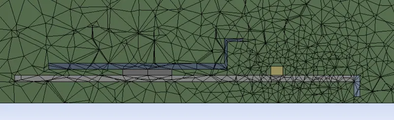
- The mesh formed is conformal which is what we needed. We can close the meshing window and go to the setup to provide the material and boundary condition for our analysis.
BOUNDARY CONDITIONS:
- We will be using steady state solver for our analysis.
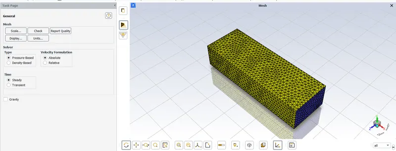
- We need to create three different materials for different components
- Fins: Copper (Cu)
- Processor: Silicon (Si)
- PCB: Fiberglass
- We will make sure we have these three material with us.
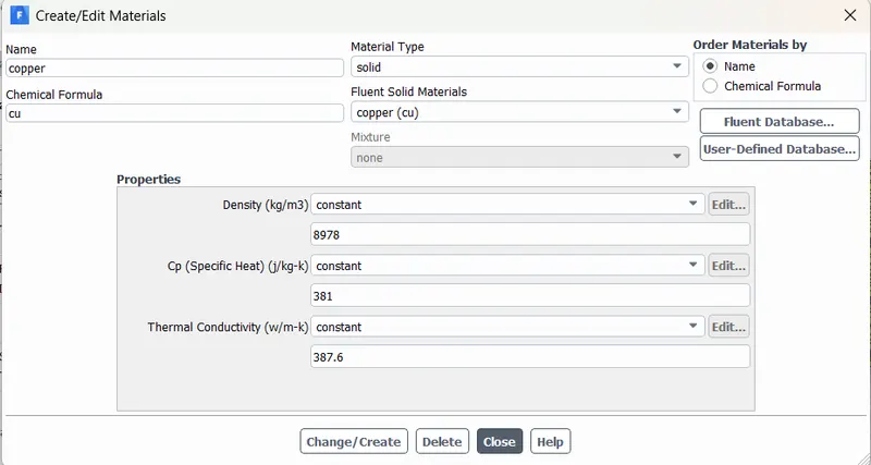
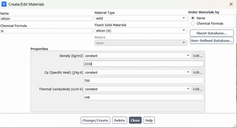
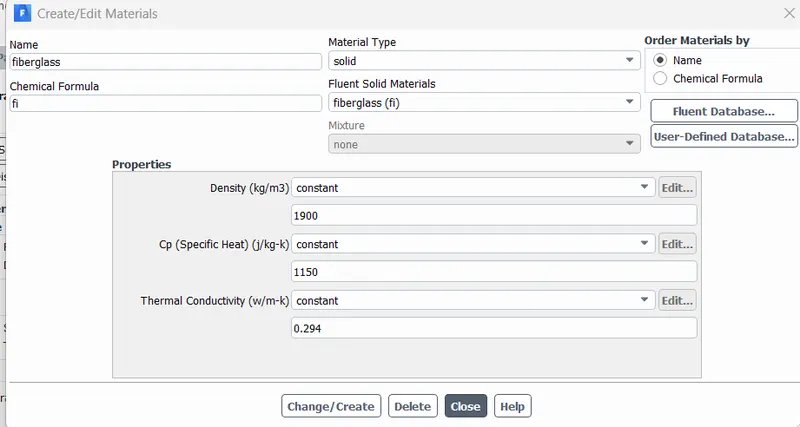
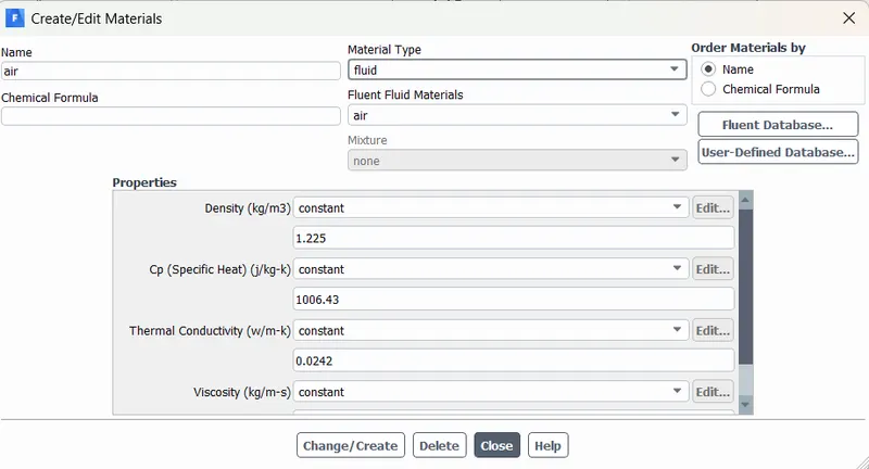
- After the materials have been defined, we need to make sure the cell zone conditions are correctly applied.
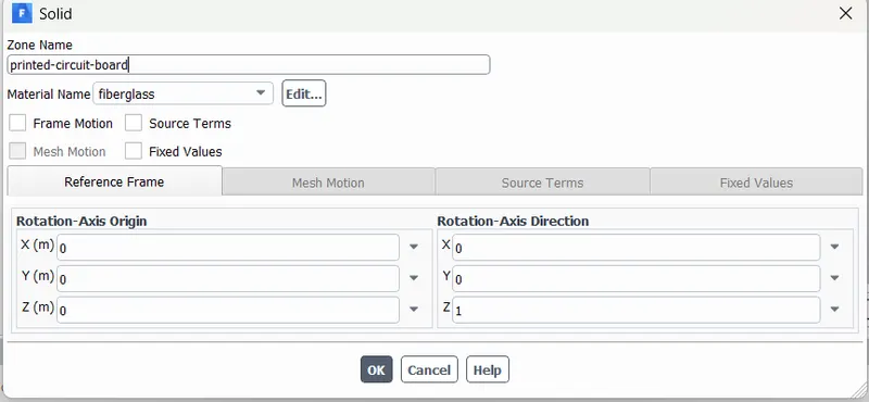
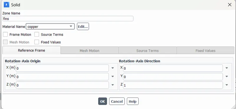
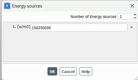
- Since the processor is an energy source where heat is generated due to resistance, we would need to calculate the heat flux generated at the processer.
- The dimensions of the processor are 8mm x 8mm x 1mm.
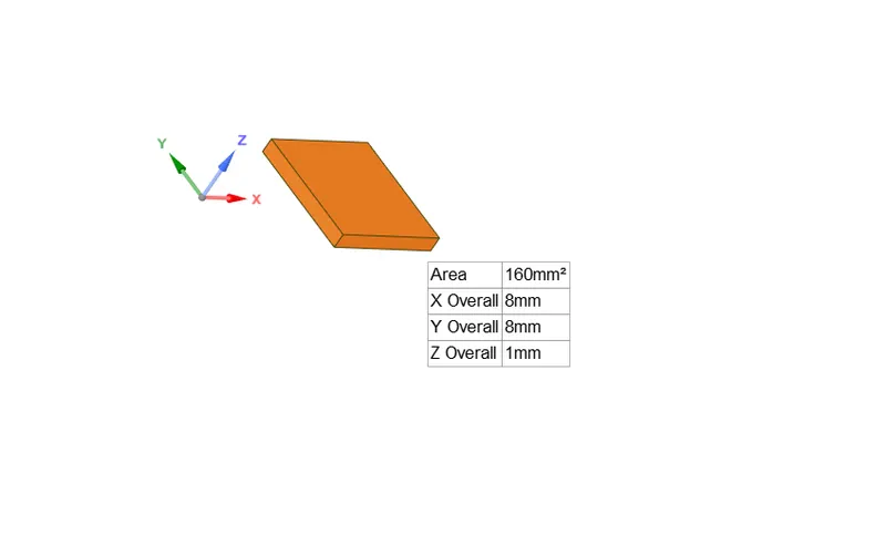
- Let the power generated by the processor is 10W. The heat generated by the processor can be said to be the heat generated per unit volume.
- Source heat = heat generated per unit volume = `(power)/ (volume)` = `(10W)/(64 xx 10^(-9)` = 156250000 W/m^`
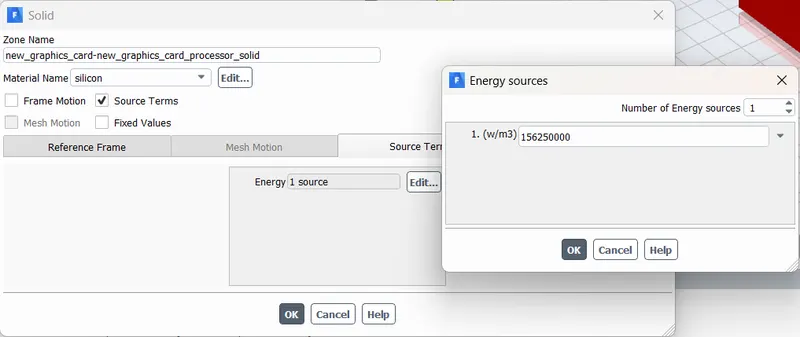
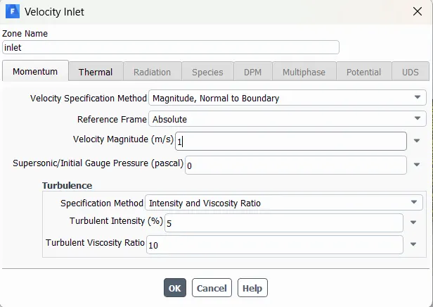
- The velocity at the inlet is 1m/s.
- The outlet will be given as pressure outlet.
- After we are finished with the boundary conditions, we can go on create the necessary plots to view the results after initialization.
RESULTS:
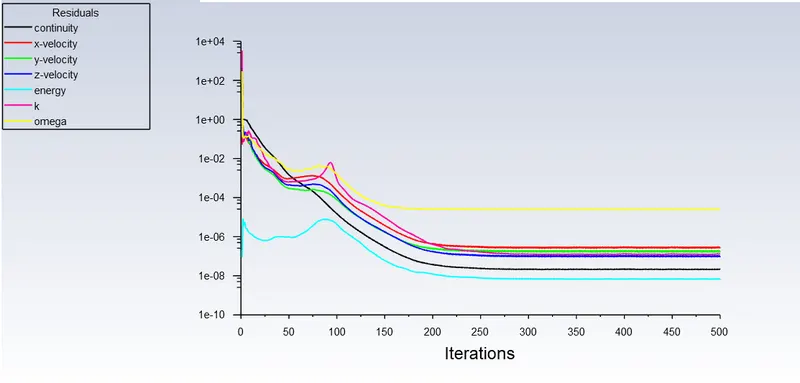
- Scaled residuals:
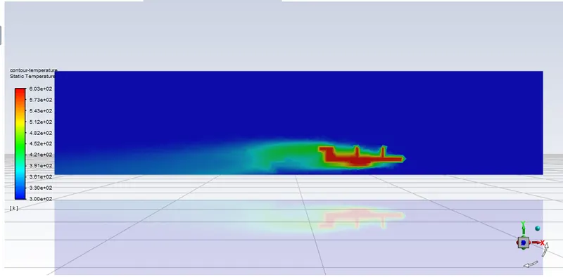
- Temperature contour:
- Velocity contour:
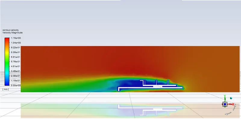
- We can see the areas where we need to improve the mesh in order to study the results better.
REFINED MESH:
Case 1: Inlet velocity = 1m/s.
For refining the mesh, we will reduce the mesh size in areas where the heat transfer takes place on a greater extent i.e., the processor and fins.
The boundary conditions are kept same.
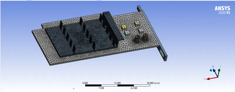
- Fins:
- The fins were meshed with a mesh length of 0.5mm.
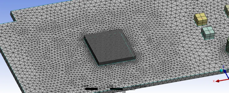
- Processor:
- The processor was meshed with a mesh length of 0.25mm.
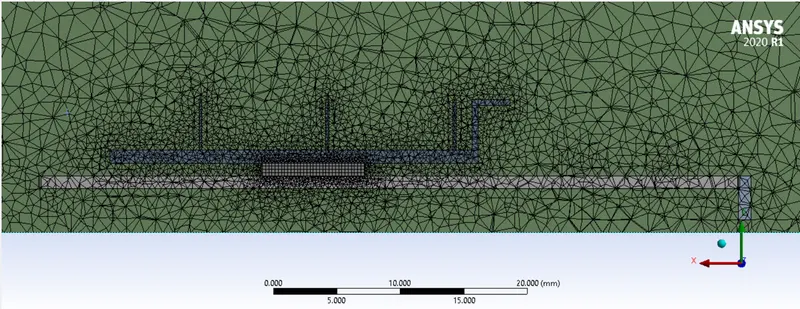
- The element length for the remaining section was kept to be 2mm.
RESULTS OF REFINED MESH:
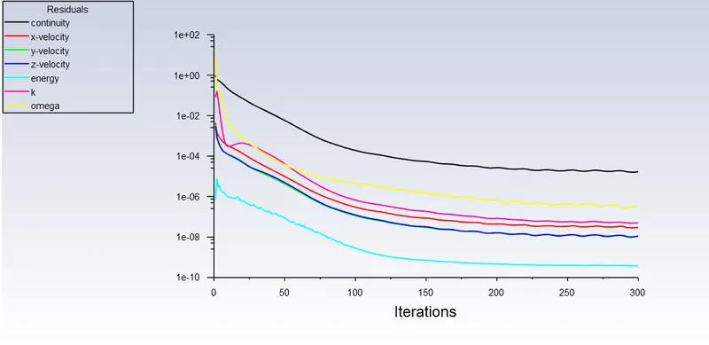
- Scaled residuals:
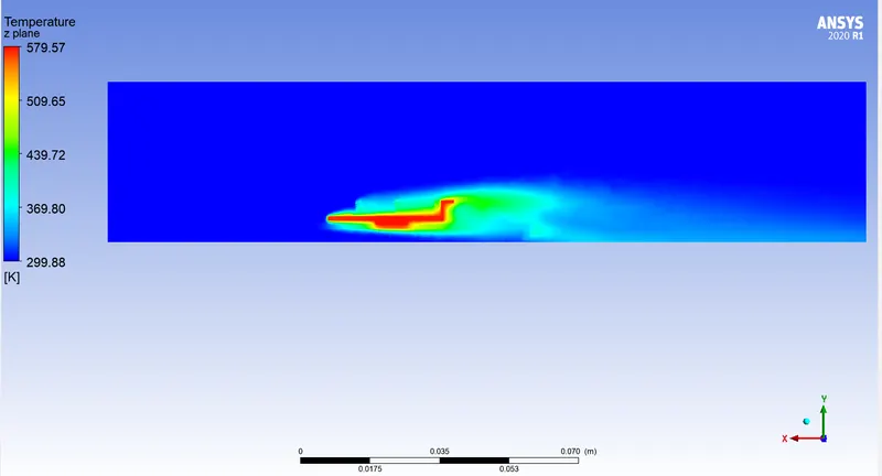
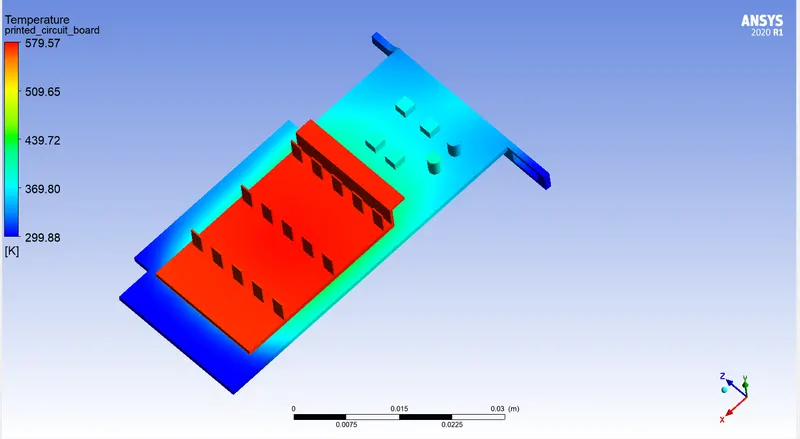
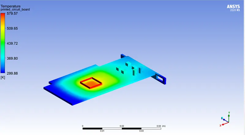
- Temperature contour:
- Velocity contour:
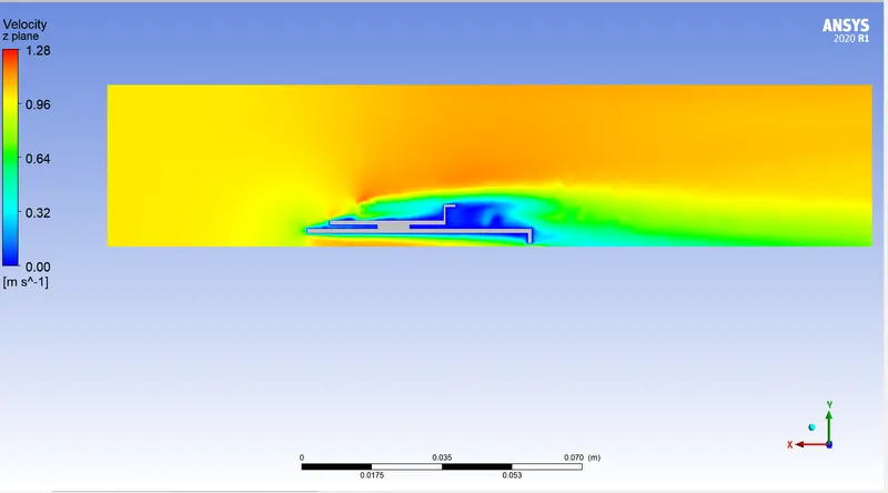
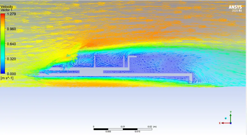
- Temperature contour of processor:
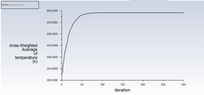
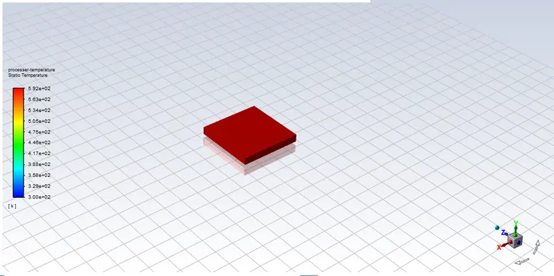
Temperature at processor for case - 1: 578K = 304.85C
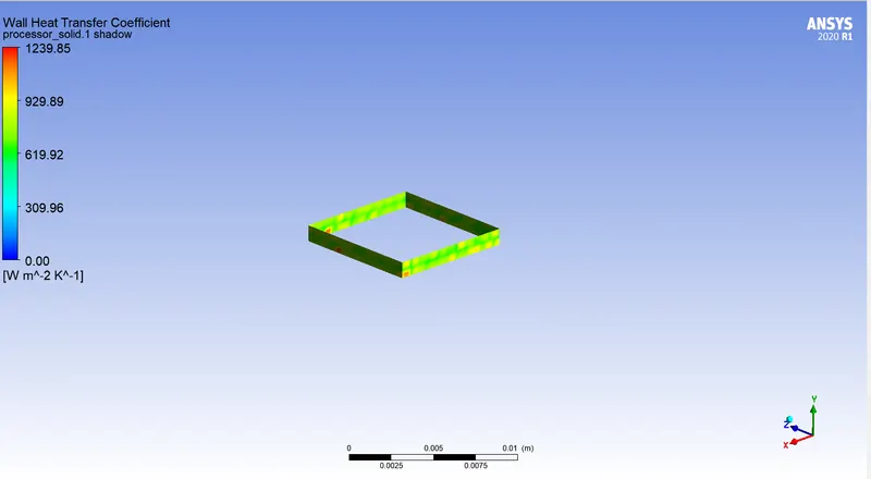
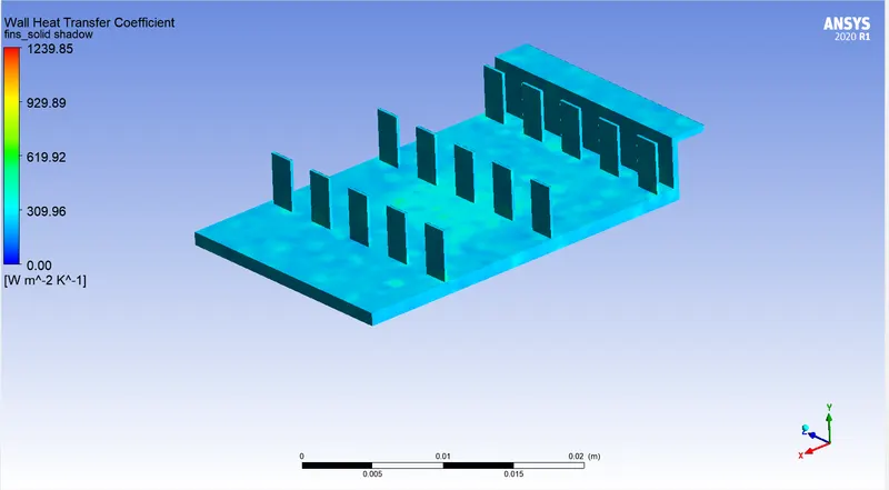
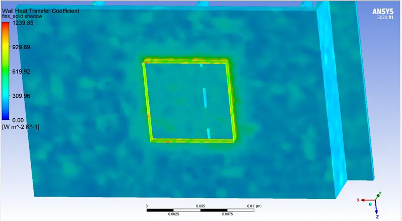
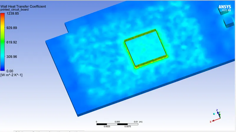
- Wall heat transfer coefficient:
1. Processor
2. Processor on fins:
3. Processor on PCB:
Case 2: Inlet velocity - 3m/s.
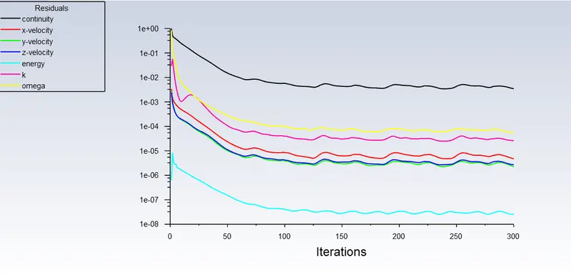
- Scaled residuals:
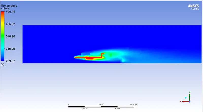
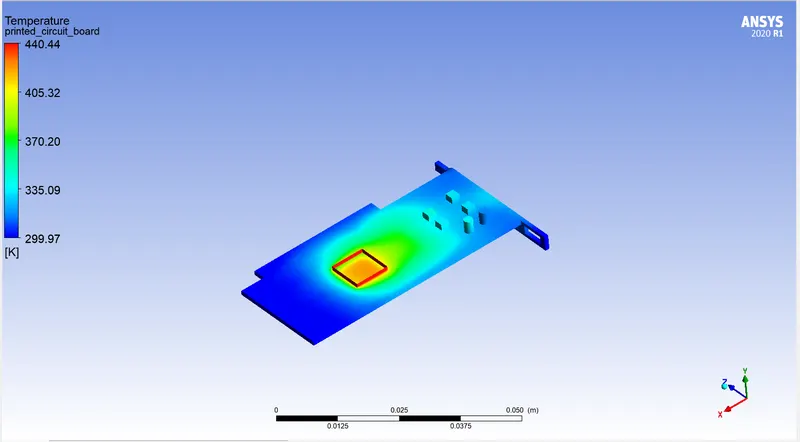
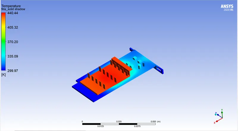
- Temperature contour:
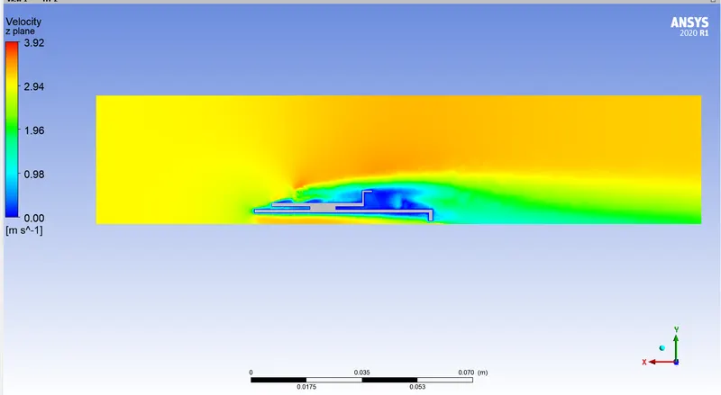
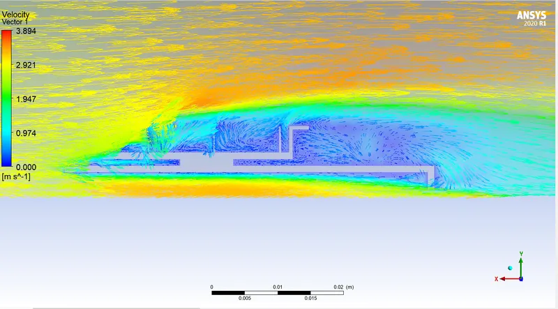
- Velocity contour:
- Temperature at processor:
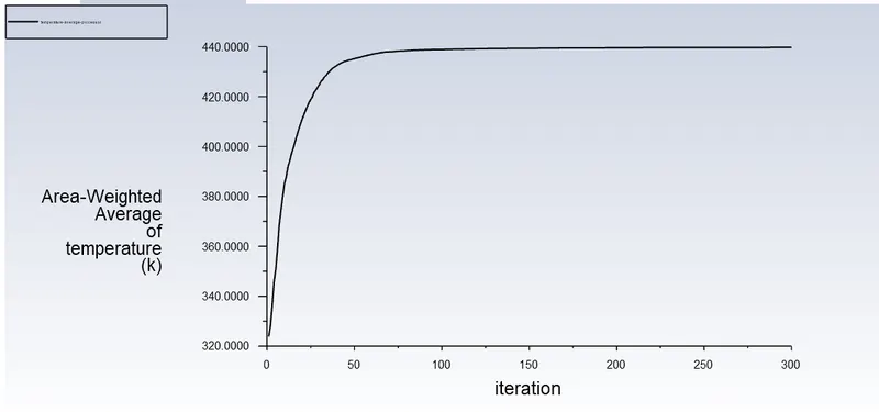
Temperature at processor for case - 2: 439k= 165.85°C
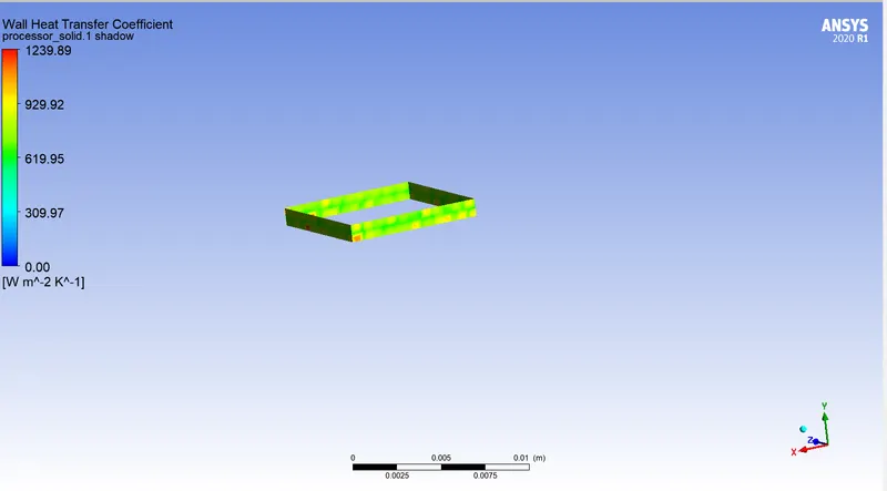
- Wall heat transfer coefficient:
1. Processor:
2. Processor on fins:
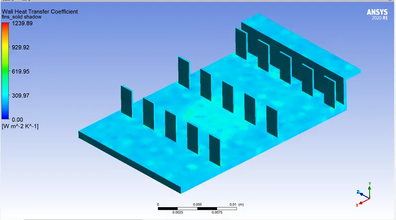
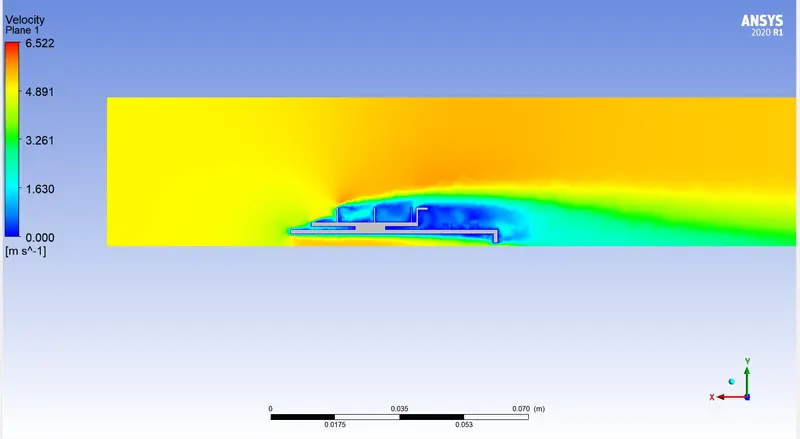
Case 3: Inlet velocity = 5m/s
- Temperature contour:
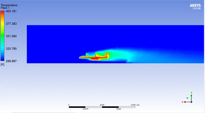
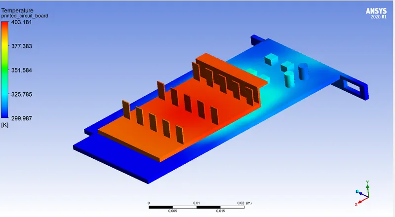
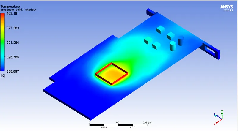
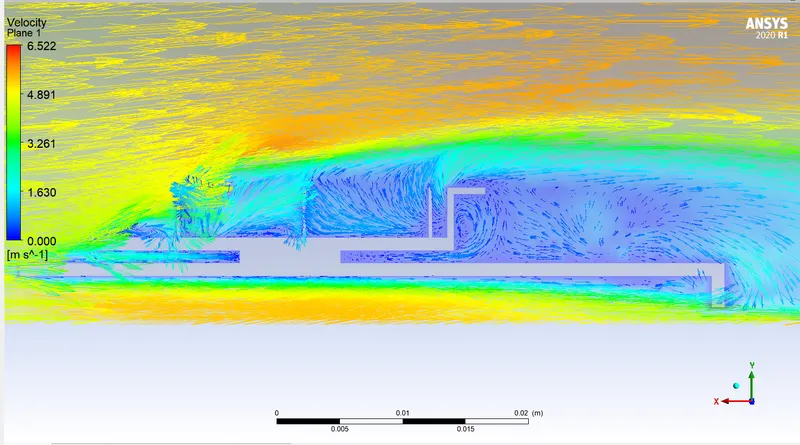
- Velocity contour:
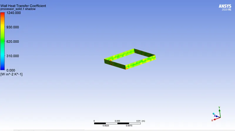
- Heat transfer coefficient:
1. Processor:
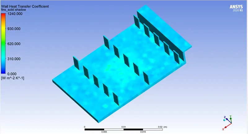
2. Fins:
- Temperature at processor:

Temperature for case - 3 is 402.24 k = 129.09°C.
CONCLUSION:
| Variable | Case - 1 | Case - 2 | Case - 3 |
| Temperature of processor | 578 K | 439 K | 402.25 K |
- As we increased the velocity of air flowing around the graphic card, we observe a drop in temperature.
- With increase in mesh quality around areas where accuracy of variable is important like processor, we can observe improved accuracy.
- Increasing velocity increases the vortex formation at the end of fins.