Week 6 - CHT Analysis on a Graphics card
week 6 challenge:
CHT analysis on graphic card.
Aim:
to simulate a graphic card on conjugate heat transfer.
introduction:
Graphic Card:
a graphic card is an expansion card which generates a feed of output images to a display device such a a computer monitor. graphical processing units (GPU) that performs a necessary computations is the main components is the main component of graphic card. most memory cards are not limited to simple output. the GPU can be used for additional processing . which reduces the load from the CPU.
In this article we shall talk about the key features and specs of graphics cards that you need to know when buying one.
- GPU - AMD, Nvidia
- Core Count
- Core Clock Speed
- Memory Type
- Memory Size
- Memory Bandwidth
- Motherboard Interface
- Thermal Design Power
- Power Connectors
- Video Output Ports - HDMI, DisplayPort
- API Support - DirectX, Vulkan
- Compute Performance - TFLOPS
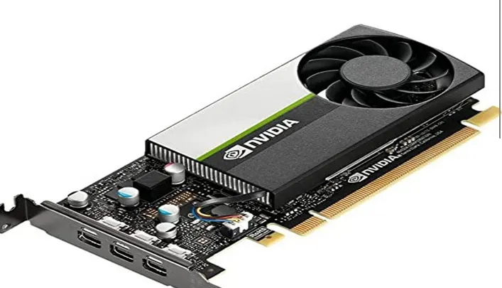
There are only 2 brands that make GPUs, namely Nvidia and AMD. Their GPUs are then used by 3rd party manufacturers to make graphics cards. Both the brands offer a really large collection of GPUs in various prices points and feature set. The GPU is often referred to as the graphics co-processor or the graphics chipset, both of which mean the same thing.
The Nvidia RTX 2080 has a 225W graphics card power, with Nvidia recommending a 650W minimum system power. The succeeding RTX 3080 (12GB) card saw the graphics card power jump to 350W, with a recommended system power of a whopping 750W.
Conjugate Heat Trnasfer:
Conjugate heat transfer is a type of heat transfer analysis between solids and fluid(s). This type of heat transfer includes both convection (between fluids) and conductive (between solids) heat transfer, as well as both forced and natural convection.
Computational Fluid Dynamics (CFD) and more specifically conjugate heat transfer (CHT) analysis can accurately predict heat transfer by simultaneous solving all the relevant solid and flow field heat transfer processes, for example: conduction through solids, free and forced convection in the gases/fluids.
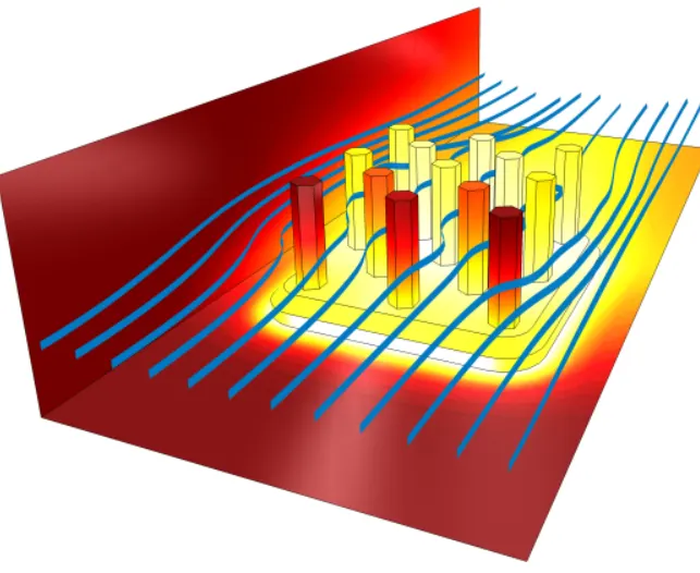
from the above example figure shows that the blue stram indicates the fluid flow and rest are solid parts.
CFD processes:
- Pre-processing. ...
Pre-processing is the first step in CFD simulation - which can help to define the parameters of the simulation in an accurate way, if done properly.
In this step, you will need to identify the domain of interest and divide it into several small segments – this includes preparing the geometry, meshing it, defining the properties of the materials involved, and setting the boundary layer and conditions.
- processing. ...
Every simulation process through a CFD program has to follow a defined set of steps. After all, simulations are a set of steps that must be complied with - as these set guidelines help to avoid getting stuck or receiving error messages in subsequent stages.
Lastly, each of these steps are interdependent on one another, which is why proper pre-processing is so critical to being with.
- Post-processing.
After getting results in the simulation stage, your next step is to analyse those results. Use the available methods such as vector plots, contour plots, data curves and streamlines to achieve this.
That way, you will get accurate reports and graphical representations. Some of the popular software tools used in the post-processing stage include EnsSight, ANSYS CFD-POST, ParaView, FieldView and Tecplot 360. Processes in this stage include:
- Calculation of the derived quantities
- Calculation of parameters
- Visualization
- Systematic data analysis and
- Debugging, verification and validation of the CFD model
CFD WORKBENCH:
pre processing:
first open the ansys workbench and create a new sript.
then double click on geomentry to open the spaceclaim.
here then , import the graphic card model to the geomentry by open>chose the file and click on open.
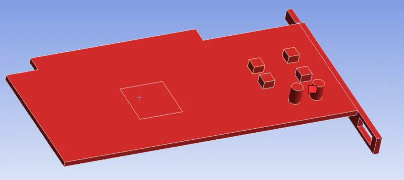
now the model has been imported.
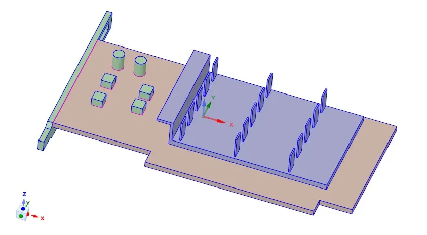
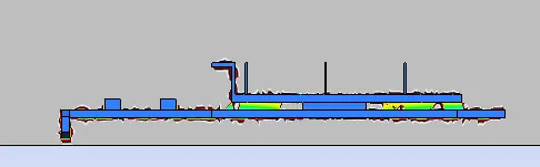
The above geometry is a rough modelof a graphics card with a PCB board, cooling fins and processor inbetween them. The model is kept inside a rectangular enclosure.
then close the window.
in geomentry we have to give share topology. this share the edges and boundary.
Meshing:
Now from the ansys flow system double click on mesh.
The model was first given a default mesh automatically generated by fluent to test the simulation. Later a refined mesh was made. The graphics card, although a hardware with countless components, was grouped into 4 basic components and named as;
- Processor
- Fin
- PCB board
name them accordingly. and the by using mesh sizing refine the mesh by 1mm for processor, fin and base.
for enclosure set the element size as 2mm.
by using inflation layer create a inflation layer at the end of the solid parts.
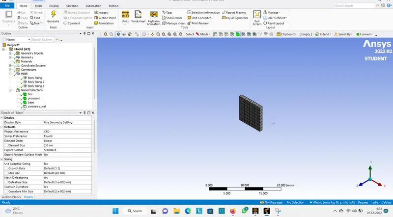
processor
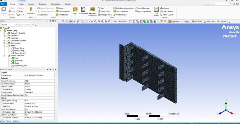
fin
base
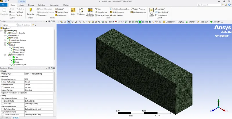
enclosure.
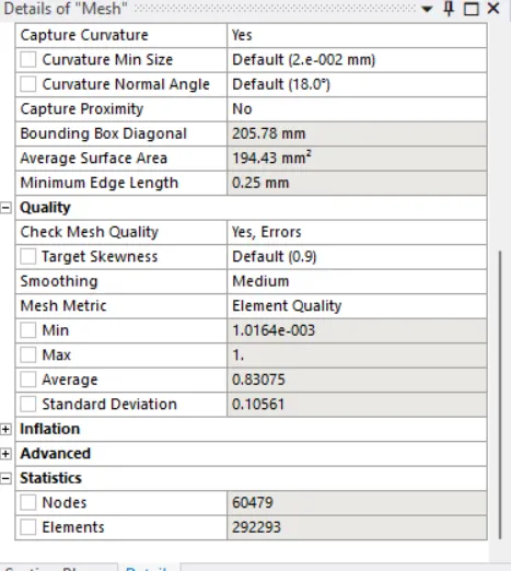
mesh size.
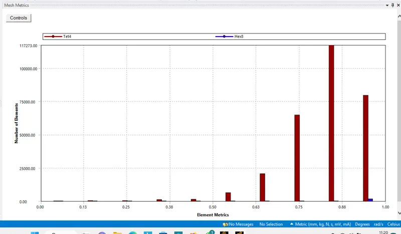
element quality.
processing::
double click on setup . now the setup has been open.
1.Solver: Steady
2.Type: Pressure Based
3.Turbulence Model: k-Omega(SST)
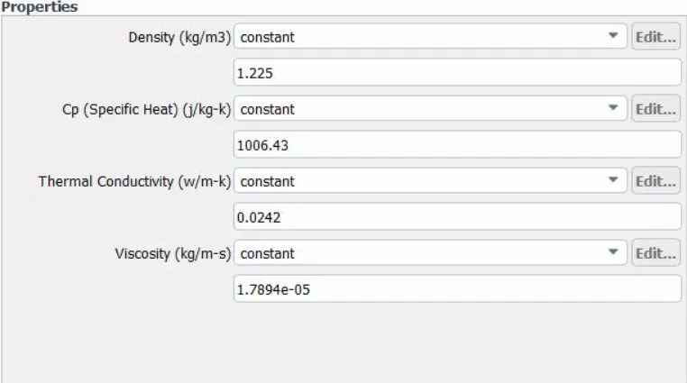
4.Materials: Different materials are used for each part, some of which are custom created
(1) copper
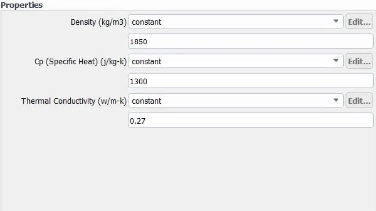
(2) Aluminium
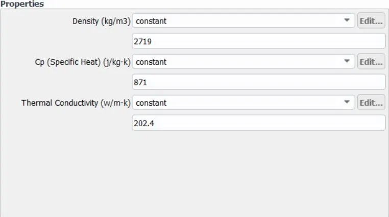
(3) Silicon
(4) Air
5.Boundaries:
- Inlet:
Type: Velocity Inlet
Velocity: 5m/s
Temperature: 300 K
- Outlet:
Type: Pressure Outlet
Pressure: 0 Pa(Gauge Pressure)
Temperature: 300 K
- Symmetry: Symmetry
- Wall: Wall
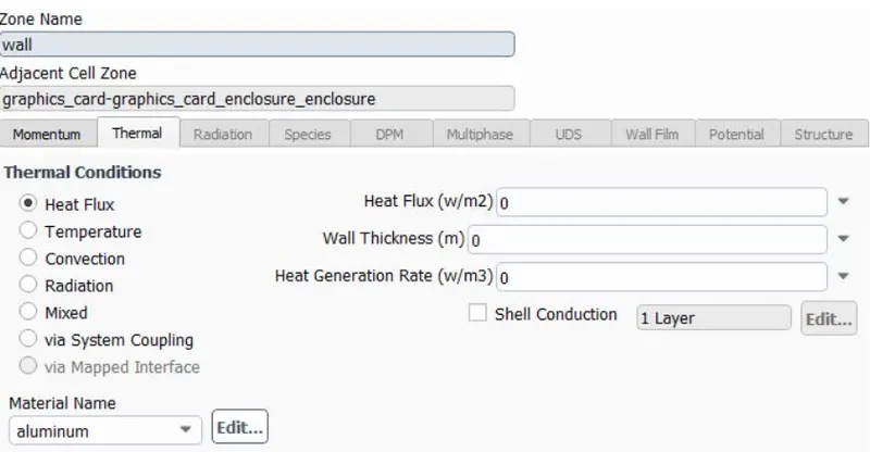
6. Cell Zone Conditions
power resources.
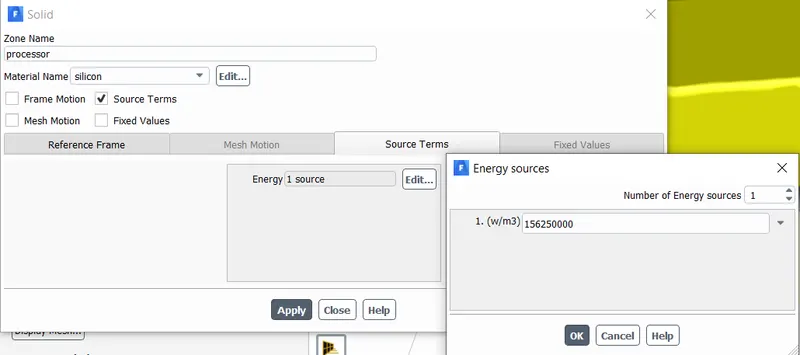
The processor is assumed as the only source of heat. The heat generated by the processor is calculated as:-
Graphics Card Power = 10W
Volume of the card = 8 x 8 x 1
= 64mm3=64e−9m
Heat Generated = P/V=10/64e−9=1.5625e^8
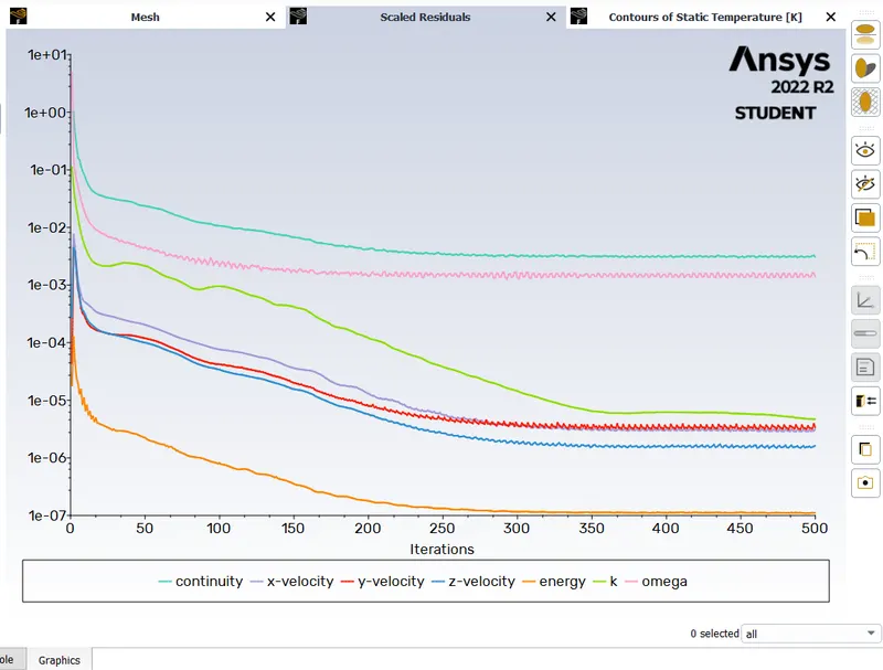
7. Solution
- Method: Standard
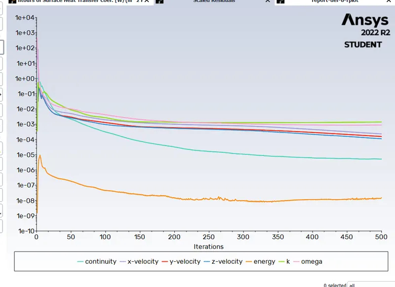
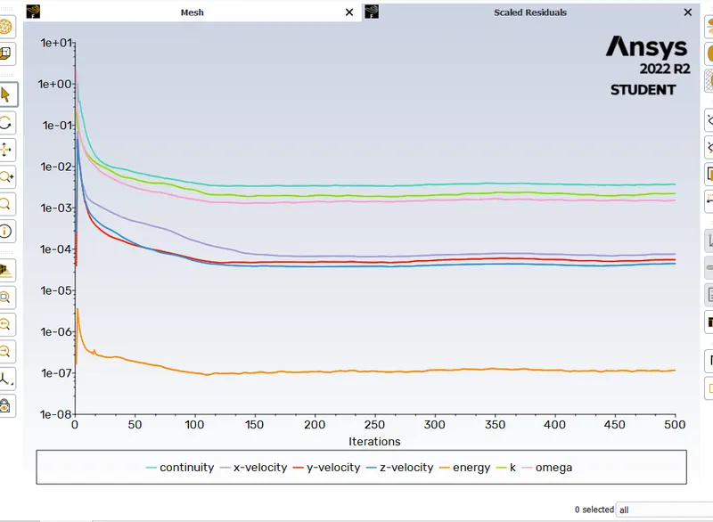
- Number of Iterations: 500
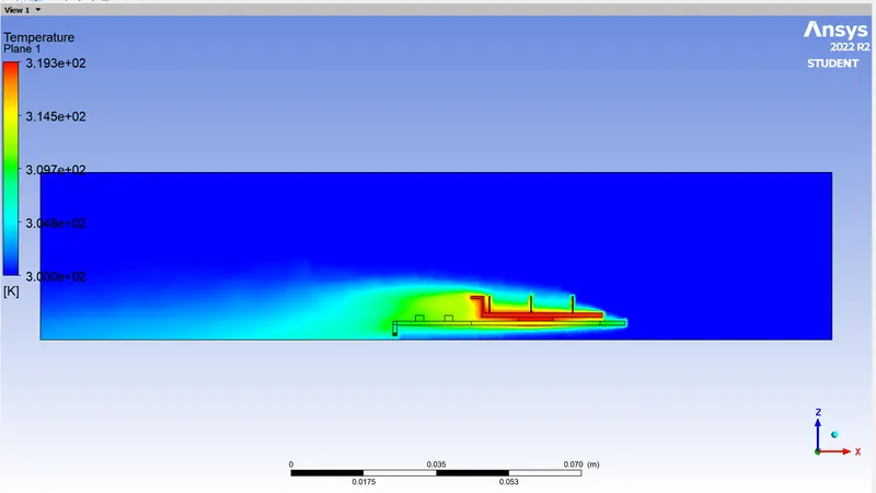
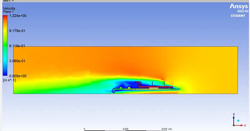
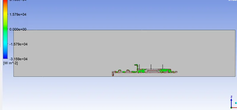
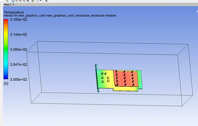
case1:
velocity of 1m/s
temperature:
velocity:
wall adjacent heat:
potential hotspot:
case2:
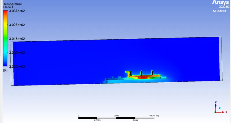
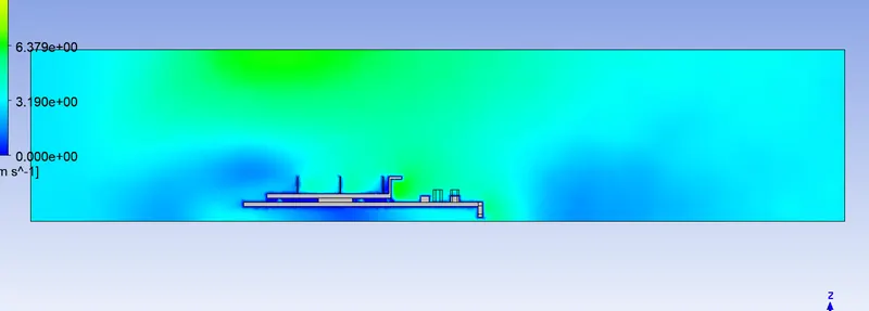
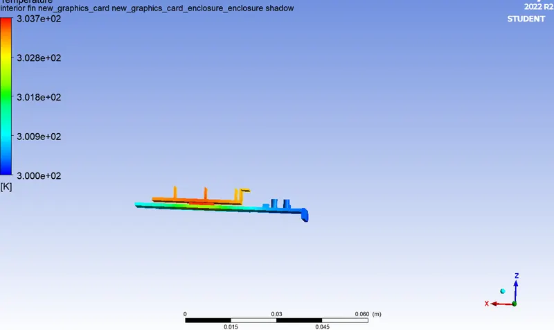
velocity of 3m/s
residual:
temperature::
velocity:
potential hotspot:
wall heat transfer:
case3:
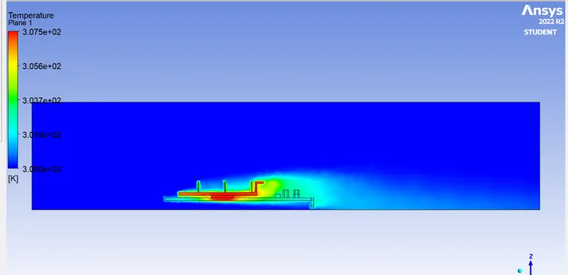
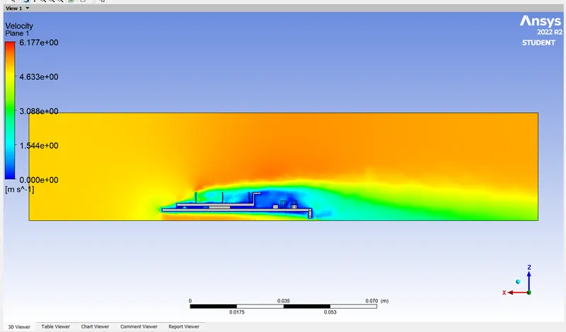
velocity of 5m/s
residual:
temperature:
velocity:
potential hotspot"
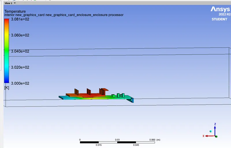
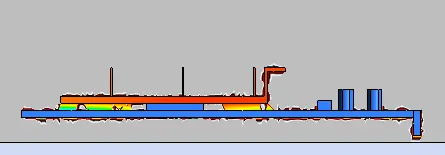
wall heat transfer coefficient:
conclusion::
- the net temperature of components of graphics cards decreases with an increase in inlet velocity.
- Hence it can be inferred that a higher inlet velocity results in better cooling and lower the average temperature thus keeping the components safe from damage.
- Furthermore, it can be observed that the temperature of components increases as the inlet velocity decreases from 5 m/s to 1m/s, also proving that higher velocity results in better cooling.
- hence, computed the simulation of conjugate heat transfer of graphic card.
-------------------------------------------------thank you----------------------------------------------------