Week 6 - CHT Analysis on a Graphics card
Problem Statement:
1. Perform conjugate heat transfer analysis on graphics card considering appropriate materials.
2. Apply refined mesh for different components of the model and reason for the same.
3. Run 3 simulations by varying the inlet velocity.
4. Find the maximum temperature and heat transfer co-efficient attained by the processor.
5. Identify the potential hotspots on the model.
Introduction.
Conjugate heat transfer (CHT) is used to describe the variation of temperature between the solids and fluids due to the exchange of thermal energy between them.
The important parameters for any heat-transfer devices are temperature, heat flux, and heat transfer coefficient of the surfaces exposed to heating or cooling environment. However accurate calculation of convective heat transfer coefficient requires boundary conditions consist of the coupling of solid and fluid fields. Such boundary conditions assume that the heat convected in or out to or from the solid is absorbed from or rejected by the fluid passing over the solid surface. This situation is highly complex to analyze theoretically since the wall and freestream parameters vary from time to time. So, an analytical solution for the simplest case of heat transfer problem necessitates a lot of simplified assumptions. Conventionally the solution for the problem has been sought explicitly for fluid and solid. That means the heat conduction in the solid is solved by assuming a constant or time-dependent heat flux at the solid boundary and the flowfield is analyzed with the assumption of either constant wall heat flux or isothermal wall boundary. However, the isothermal wall boundary condition is far away from reality in most of the practical heat transfer situations. Hence the heat transfer coefficient prediction employing isothermal boundary layer condition is also found to be erroneous To have the analytical or numerical prediction of heat transfer coefficient close to experimentally obtained values, one must focus on conjugating the boundary condition at the fluid-solid interface through a couple of heat transfer analysis. Such a coupled field study is termed as Conjugate Heat Transfer (CHT) analysis.
Applications of the CHT is widespread. Some of them are in heat treatment of materials in the manufacturing processes. The study of heat transfer and temperature distribution of the material as it undergoes various manufacturing phases. CHT analysis not restricted to manufacturing sectors but also in gas turbine blade cooling, thermocouple design, design and sizing of heat exchangers, furnace design, aerospace applications, etc
Need for heat transfer simulation on the graphics card
The main heat generation source term is the processor in the graphics card. As the temperature increases the performance of the processor drops and eventually the outputs poor graphic performance, in certain cases the computer operations stop. Hence heat sinks are provided to reduce the overheating of the processor. But the heat transfer inside a computer case between processor and heat sink is unknown hence computational flow simulation is carried out to simulate and observe the heat transfer inside the computer case and heat sink to reduce the overheating issue of the processor.
Modeling of the geometry:
Dimensions of the model:
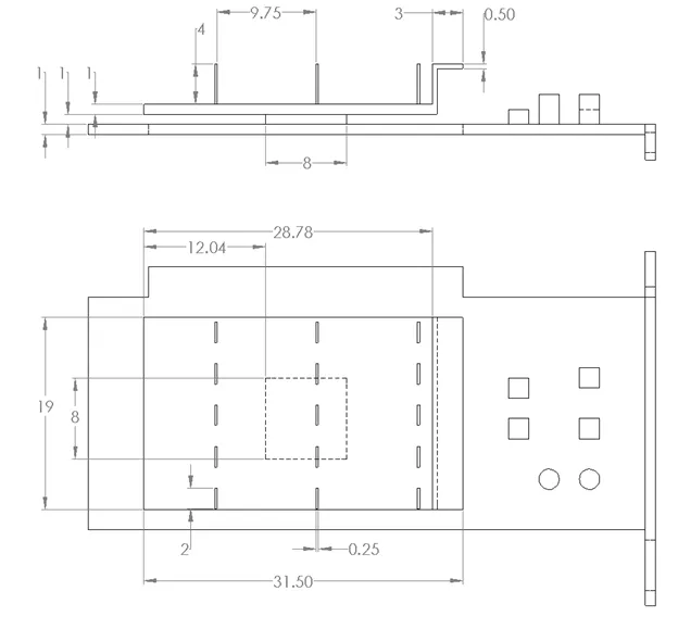
Dimensions of the enclosure:
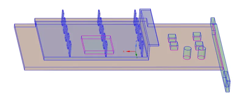
Share topology:
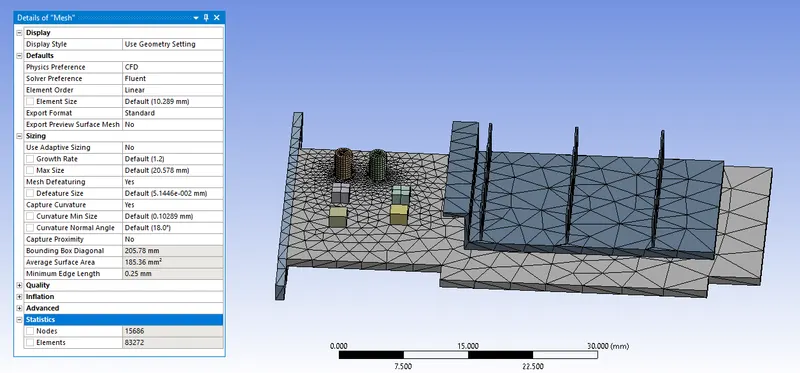
Mesh Parameters for base mesh:
Setting up physics:
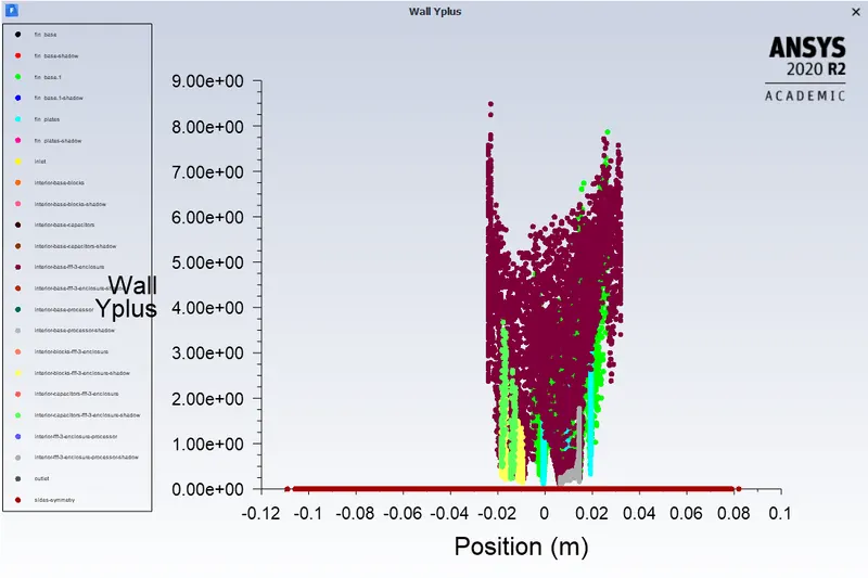
1. K-omega turbulence model is used as this heat transfer coefficient is a wall phenomenon. K-omega turbulence model is accurate at boundary layers. Mesh parameters are assigned such that the Y+ range is less than 5.
2. As the temperature is involved energy equation is enabled under the physics menu.
3. Apart from the enclosure where the fluid flows remaining components of the graphics card are assigned solids which are made of aluminum.
4. The main source of heat generation is from the processor which is assigned 100W in the cell zone for processor under source terms.
5. Contour plot is created for temperature for the graphic card components which is used for the animation creation.
Results for base mesh shown below:
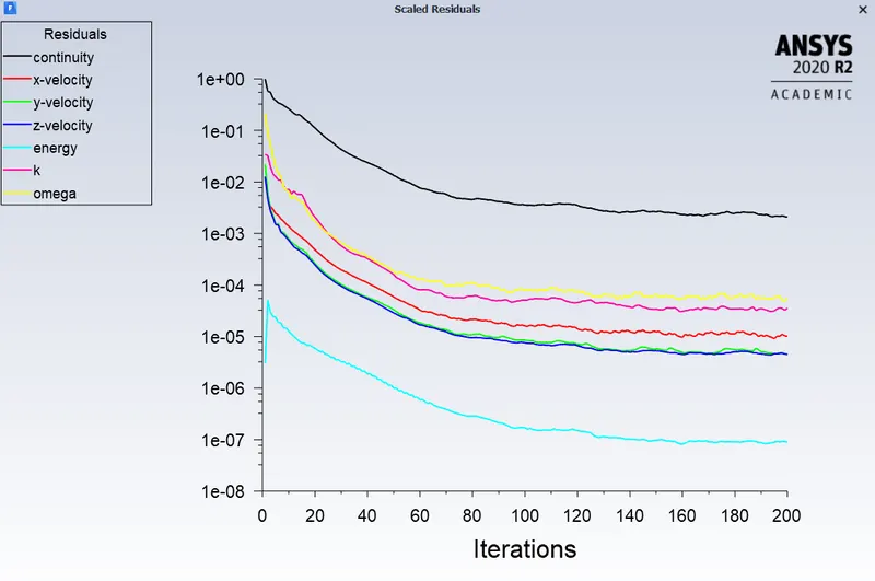
Residuals.
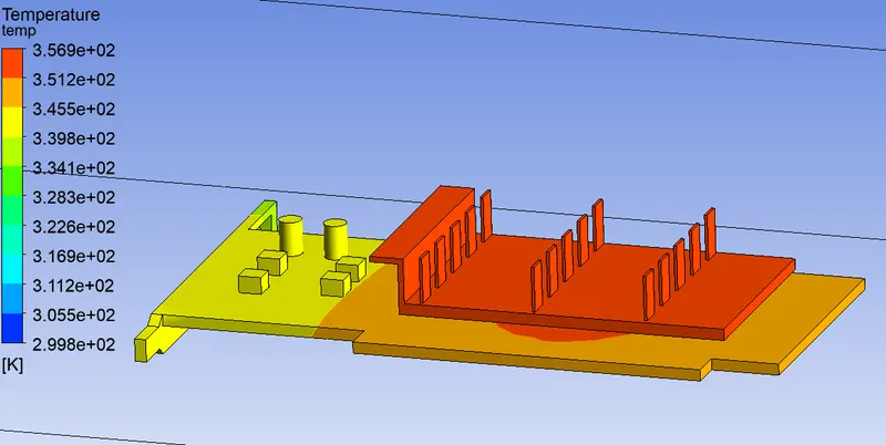
Global Temperature contour.
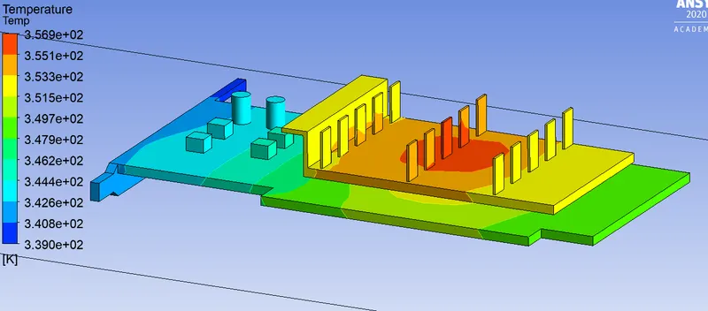
Local Temperature contour.
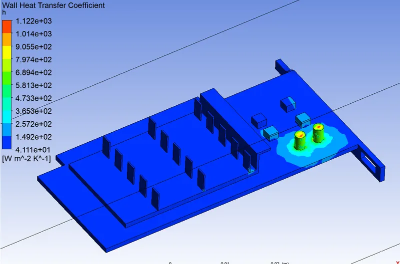
Contour plot of Heat Transfer Co-efficient.
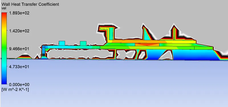
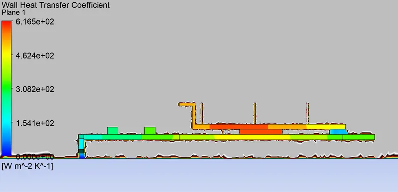
Wall heat transfer Co-efficient using a plane.
Vector plot for Recirculation region with temperature as the variable:
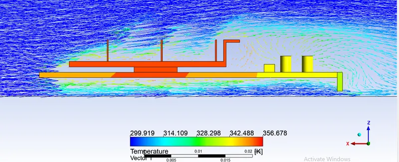
From the base mesh, we can see that there are local hotspots created at the unwanted locations which might be due to the mesh size elements. Hence refinement of the mesh is done at fins, fin base, and processor to calculate accurately temperature and wall heat transfer coefficient and also to visualize the recirculation regions formed at the graphic card which have a significant effect in the heat dissipation.
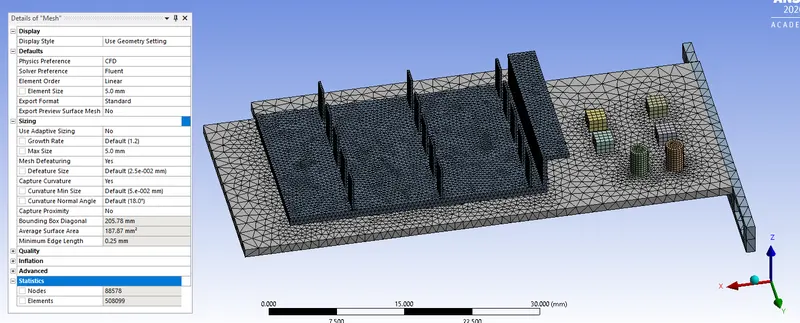
Refined mesh parameters.
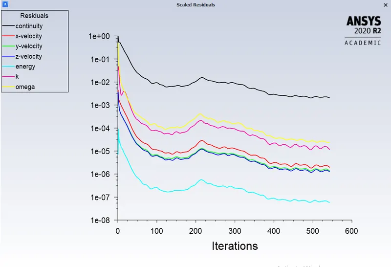
Residuals:
Y+ plot.
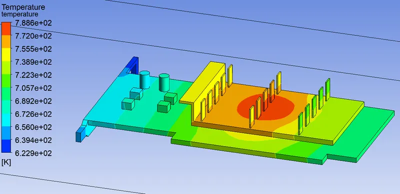
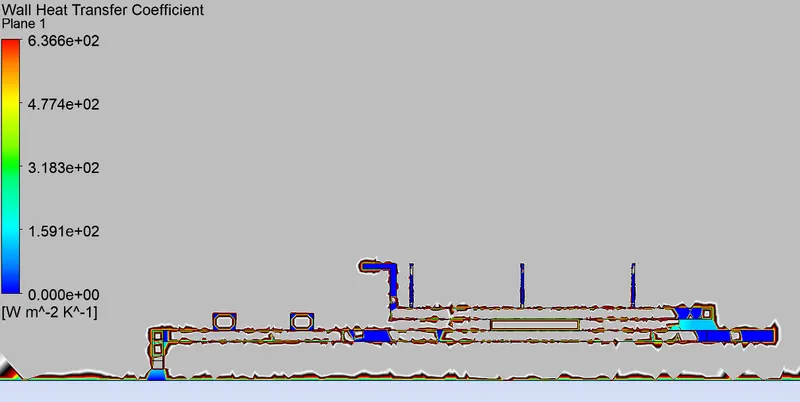
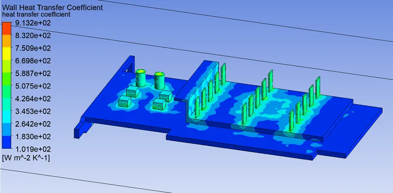
Results considering inlet velocity of air 5 m/s.
Global Temperature Plots.
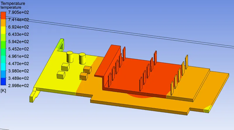
Local Temperature Plots.
Wall heat transfer Coefficient:
Contour plot for heat transfer coefficient.
Vector plot for Recirculation region with temperature as the variable.
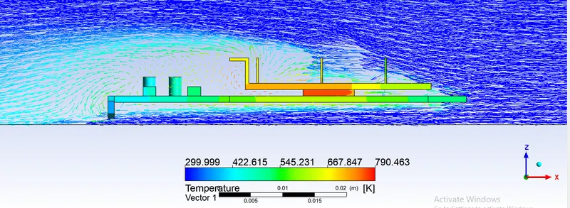
Results considering inlet velocity of air 3m/s.
Global Temperature Plot:
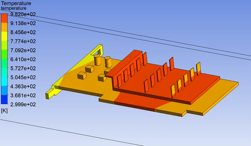
Local Temperature Plot:
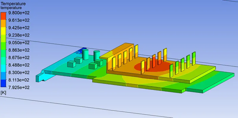
Contour plot of Heat Transfer coefficient
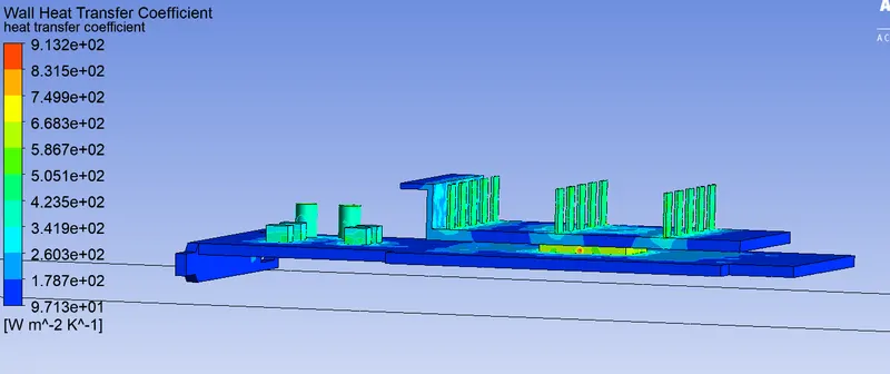
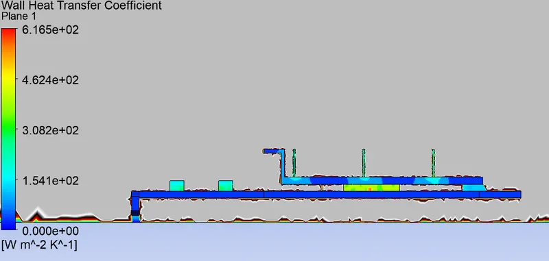
Wall Heat transfer co-efficient using Plane.
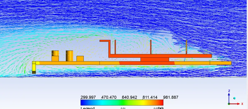
Vector plot for visualizing recirculation region.
Results for considering inlet velocity of air 1 m/s.
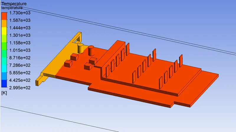
Global temperature.
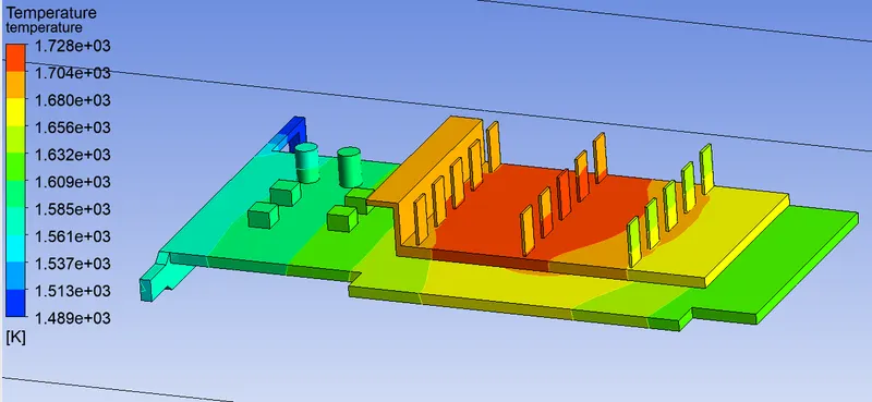
Local Temperature plot.
Contour plot of Heat Transfer Co-efficient.
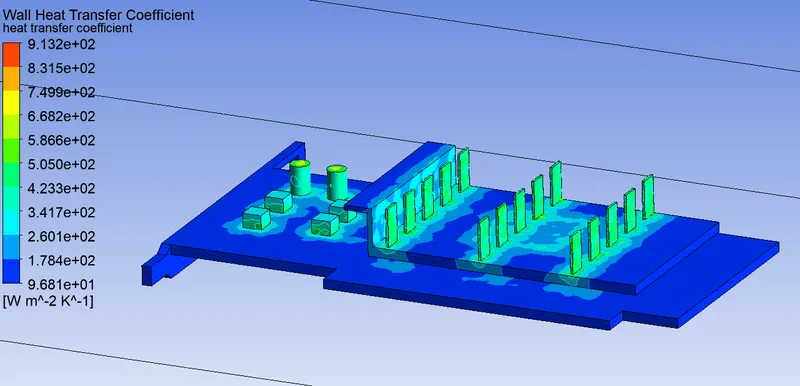
Wall heat Transfer Co-efficient.
Vector plot for visualizing recirculation region.
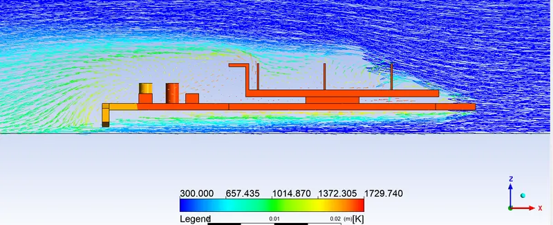
Table comparing the maximum temperature and wall heat transfer Co-efficient for different inlet velocities of air.
| Inlet velocity of air in m/s | Maximum Temperature in K | Wall heat transfer Coefficient in W/`m^2`-K |
| 5 | 790.5 | 636.6 |
| 3 | 982 | 616.5 |
| 1 | 1728 | 616.5 |
Inference:
From the residual plot, the change in the gradients is very small with which we can conclude that the solution has converged.
From the temperature plot of the coarse mesh, the high-temperature points are found at fins, processor, and base area near the processor. As the wall heat transfer coefficient is a wall phenomenon and fins dissipate a large amount of heat which results in higher heat transfer co-efficient but the coarse mesh heat transfer for fins and other components in the graphics card has the same values. Hence refinement of mesh is done for fins and base of the fin and base of the graphic card in order to calculate the wall heat transfer coefficient at the fins and base.
The high-temperature regions are found at the center of the fins, base, and the processor walls. With further iterations, the temperature is distributed to other regions in the graphics card in the direction of the inlet airflow. Conduction occurs where there is a contact region between the solids in this case it is between processor and fins and processor and base. Convection occurs when the heat generated in the components of the graphic card is removed by the inlet airflow. The maximum temperature in the components is inversely proportional to the inlet airflow velocity. With the increase in the airflow velocity, the heat removal process by convection is faster. And also recirculation of air (vortex) at appropriate places will increase the heat transfer efficiencies hence greater amount of heat is removed by convection.