Week 6 - CHT Analysis on a Graphics card
AIM:
In this challenge the graphics card is need to run the simulation for best possible mesh with combination of coarse and refined mesh in different regions. Explain the reason for choosing the particular mesh settings.
Your Objectives:
- Run the simulation by varying the velocity from 1m/sec to 5m/sec for at least 3 velocities and discuss the results.
- Find out the maximum temperature and heat transfer coefficient attained by the processor.
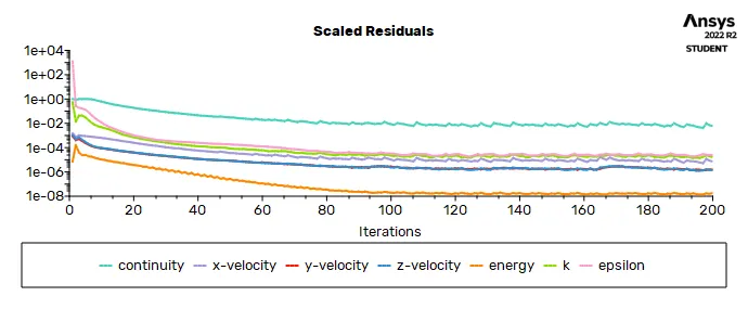
- Prove that the simulation has achieved convergence with appropriate images and plots.
- Identify potential hotspots on the model.
INTRODUCTION:
GRAPHICS CARD:
video card, also called graphics card, integrated circuit that generates the video signal sent to a computer display.
The card is usually located on the computer motherboard or is a separate circuit board but is sometimes built into the computer display unit.
CHT ANALYSIS:
The Conjugate Heat Transfer (CHT) analysis type allows for the simulation of heat transfer.
This heat tansfer occurs between solid and fluid domains by exchanging thermal energy at the interfaces between them.
Typical applications of this analysis type exist as,
but are not limited to,
the simulation of heat exchangers,
cooling of electronic equipment,
and general-purpose cooling and heating systems.
ANSYS:
The CHT analysis of the graphics card is carried out in the ansys workbench with the help of the fluid flow (fluent).
The fluid flow simulations contains several steps are :
1.geometry
2.Meshing
3.Setup
4.Solution
5.Results.
By the help of all this software the CHT anaysis is analysied properly and completely.
GEOMETRY:
The model of the graphics card is downloded from the challenge page .
that model is insert in the spaceclaim ,that model contains GPU which is mounted on base.
cooling unit along with fins are presentb above the GPU.
then the shared topology is enabled in fluent and by using shareprep function, a conformal geometry is made.
the ansys workbench is updated with the information which are newly added and modified in the spaceclaim .
MESHING:
The mesh is opened in after update the model in the ansys workbench.
CASE1:
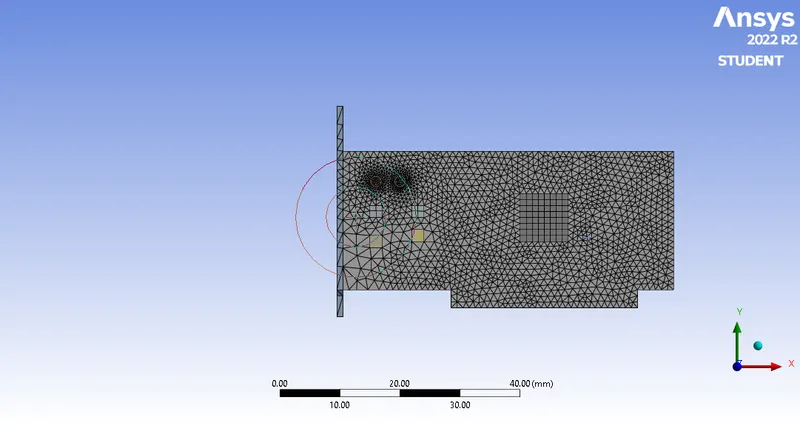
the model is loaded and generate the mesh initially.
the naming is given to the respective faces and bodies (inlet,outlet,body,fins,processor.)
in the mesh - insert-sizing -select the base geometry and aplied on geometry.
then give the size as 1mm and the curvatuture is 18 degree.
the overall mesh element size is 10 mm.
the fins are and selected as the same sizing is applied as 1mm mesh length.
the processor also mselcted in the sizing element and that is meshed in the mesh length of 1 mm.
the meshed graphics card is:
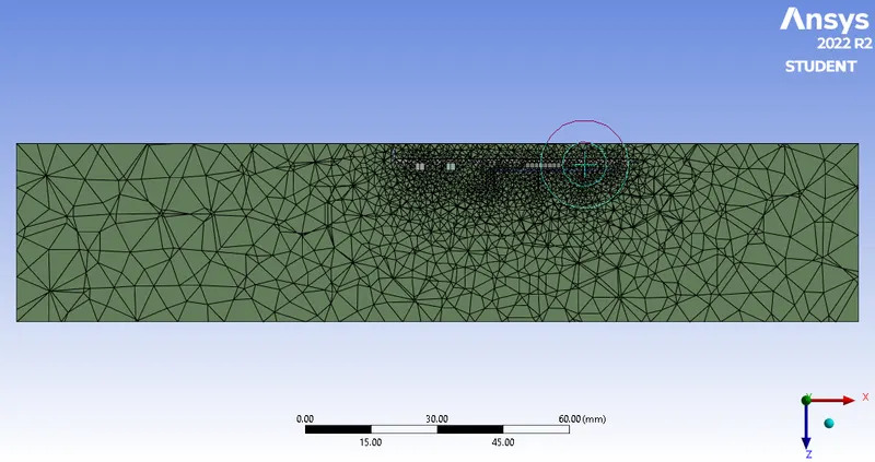
the meshed fins, processor and base:
CASE 2:
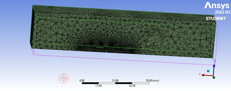
In this case the model is refined furthur in order to better analysis of the graphics card model.
the total mesh length of the model is as 0.5 mm
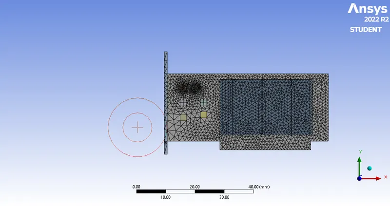
and the inflation layer is added for all the fins, processor,base with the maximum thickness of 4mm.
rest all the meshing length of fins,base and processer is same as the previous one.
the meshed graphics card medel in the refined mesh length.
the inner parts of refined mesh is:
SETUP:
after updating the model in the ansys workbench the setup and the fluent is opened.
the fluent is opened with double precission and 4 solving processor.
the model is loaded in the fluent interface.in the setup physics deck the the energy equation is on and the epsilon equation is used .
the material is used as a air. the cell zones the surface terms are openrd .
with the 1 source -edit- put the heat generation as 765000.and click ok.
in the boundary conditions velocity is setup in the 2m/s.
the outlet is set as 0 pressure.
then the inatilize trhe hybrid initialization.after that in the result deck the contors are created for the velocity anbd the temperature.
the visualization is only the fins,processor,base.and put that as the active. and click save/display.
then in the solution deck the calculation is carried ou with the 200 iterations.
this setup procedure is same for both of the cases.
the resuidal of the graphics card design is:
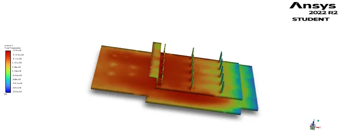
the temperarture of the graphics card at the vellocity of 2m/s.
RESULT:
the result is opened (cfd post is opened)after updating the solution in the ansys workbench.
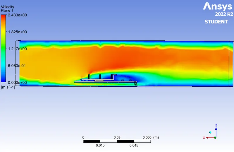
the zx plane is created inm the model in order to determine the flow velocity.
the plane is created by the help of the insert -plane-zx plnae.
in the colour change constant into variable and change the velocity and click apply.
then the velocity of the model which is passed through that is clearly shown in the plane.
the velocity of trhe model is flow is shownm below:
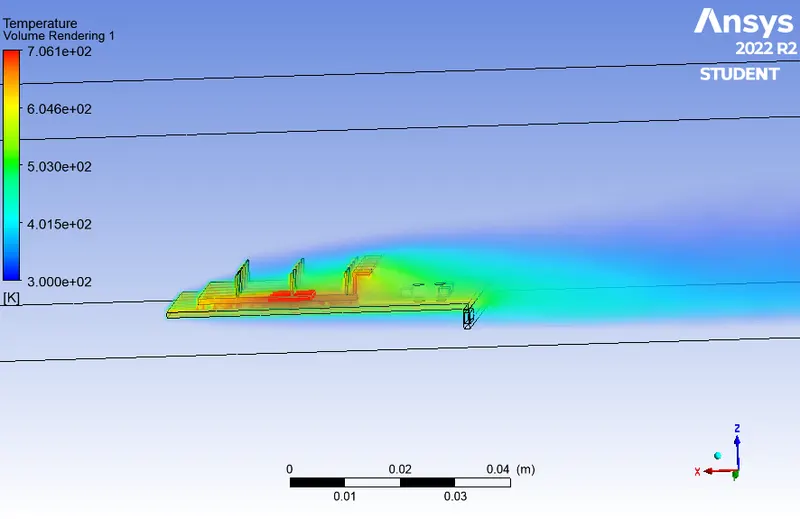
thr temperature is also detected of the model is also carried out.
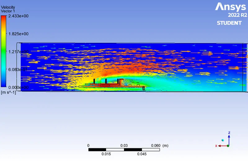
the in the menu bar the vector is created and displayed in the same plane.
the plane vector is given below:
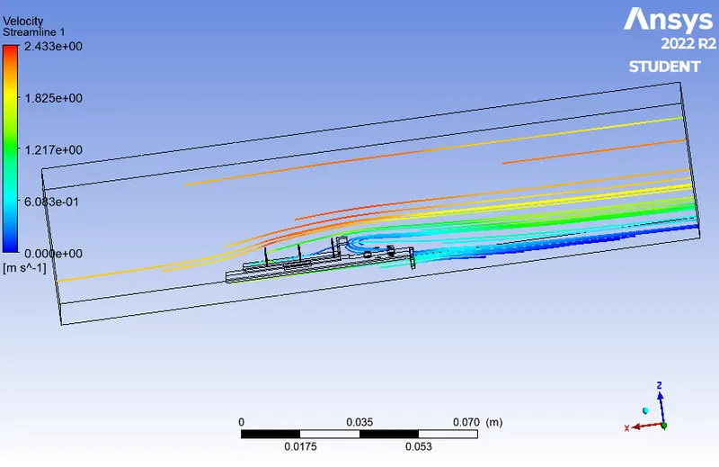
the streamline flow over the graphics card is also shown below:
the temperatur volume rendering of the model of the graphics card.:
the temperature distribution over the graphics card model is:
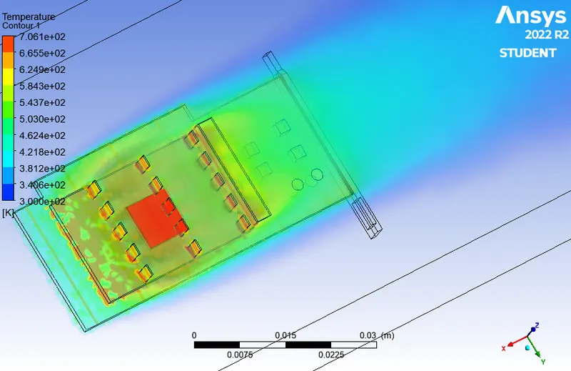
POTENTIAL HOSPOTS OF THE MODEL:
A “persistent” spatiotemporal hotspot is defined as a region where the rate of increase in observations is constantly high over time.
hence the simulation over the graphics is processed succesfully.