Week 6 - CHT Analysis on a Graphics card
CHT Analysis on a Graphics card
Aim:
- Perform a steady-state conjugated heat transfer analysis on a model of a graphics card.
- Select the appropriate materials for the simulation.
- Mesh the geometry with a desirable combination and Explain the mesh setting used on this model.
- Simulate by varying the velocity from 1m/s to 5m/s for at least 3 velocities and discuss the results.
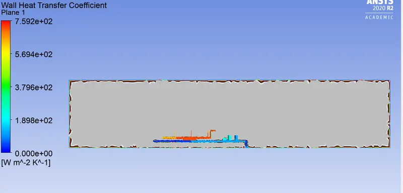
- Find out the maximum temperature and heat transfer coefficient attained by the processor.
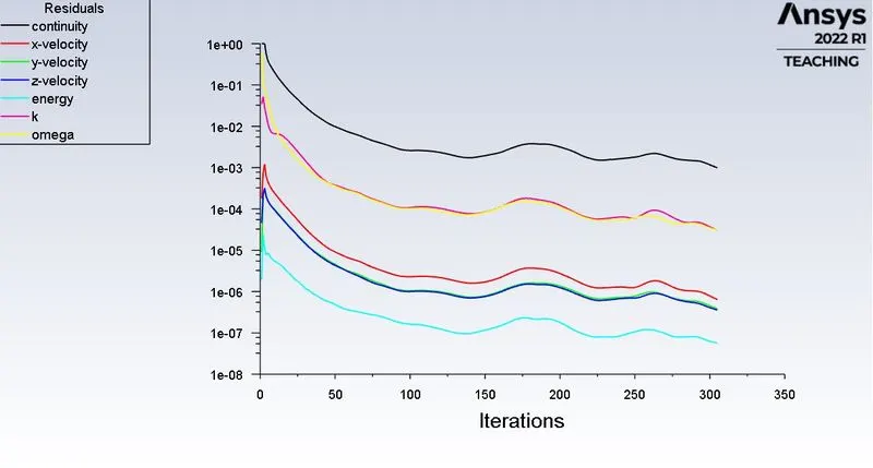
- Prove that the simulation has achieved convergence with appropriate images and plots.
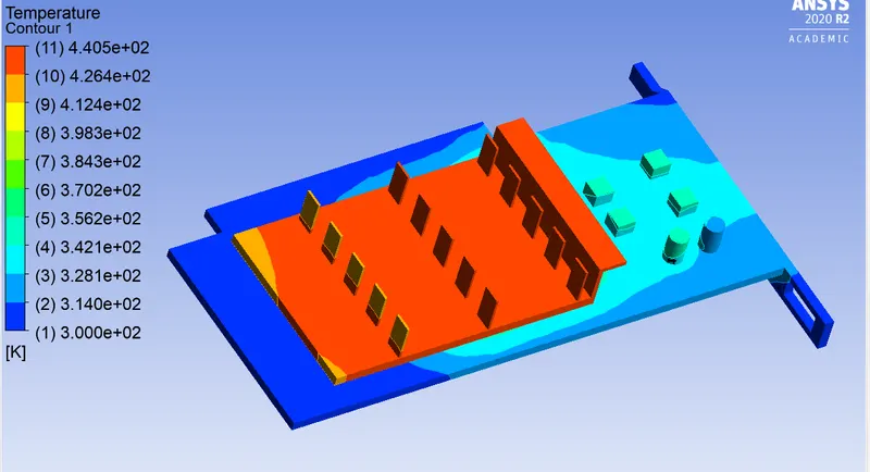
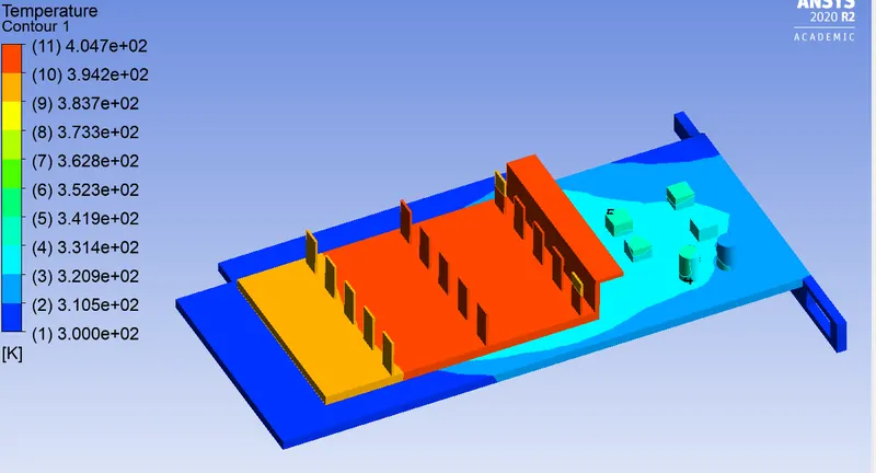
- Identify potential hot spots on the model.
Objectives:
- Import graphics card model in the space claim and active share topology.
- Mesh the model using proper inflation layer and face sizing.
- Open fluent setup and perform steady-state conjugated heat transfer simulation on meshed model.
- Prove that the simulation has achieved convergence with appropriate images and plots.
- Check the mesh independence of the model by performing the same simulation with different densities of mesh.
- Try simulating the solution using different velocity in the range of 1m/s to 5m/s
- Find out the maximum temperature and heat transfer coefficient attained by the processor.
- Identify potential hot spots on the model.
INTRODUCTION:
GRAPHICS CARD:
A graphics card is an expansion card that generates a feed of output images to a display device. A computer’s CPU works by either enabling signals to pass through its microscopic transistors or by blocking them. As electricity passes through the CPU or gets blocked inside, it gets turned into heat energy. While a processor in a high-performance workstation may run hot due to heavy use, a processor in a regular computer that overheats is almost always a sign of a malfunctioning system.
Computer cooling is required to remove the waste heat produced by computer components to keep components within permissible operating temperature limits. Components that are susceptible to temporary malfunction or permanent failure if overheated include integrated circuits such as central processing units, chipsets, graphics cards, and hard disk drives.
CONJUGATE HEAT TRANSFER:
Conjugate heat transfer is a process that involves the variation of temperature within solid and fluid due to thermal interaction between them. CHT analysis allows the simulation of the heat transfer between solid and fluid domains by exchanging thermal energy at the interfaces between them. CHT analysis is advantageous in accurately simulating the surface temperature and heat exchanging capabilities of various devices and engineering machines.
APPLICATIONS:
CHT analysis helps to understand the effectiveness of various thermal systems involving solid and fluid mediums. It helps to simulate and understand thermal systems like heat sinks, coolers, heat exchangers, exhaust ports of vehicles, internal combustion engines, boilers, HVAC, Electronic components cooling, etc...
PROCEDURE:
GEOMETRY:
At the start of the simulation process, the made-up (Rough) geometry of the graphics card which also already includes an encloser was imported into the Space Claim. The various components involved in the geometry are highlighted with the orange rectangular boundary line which includes the base (circuit board), Graphics card processor, Fins attached to the processor, and other components.
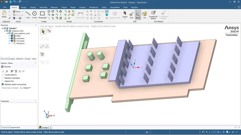
The geometry and flow domain consists of a flat circuit board with a heat-generating electronic processor chip and some other components connected to it. Heat is conducted through the source (processor), the board mounted on it and the fins attached to the processor. A stream of air flows over the fins, processor, and board, causing simultaneous cooling of the solid components and heating of the airstream due to convection. Thermal energy is also transported due to the complex flow field.
Meshing
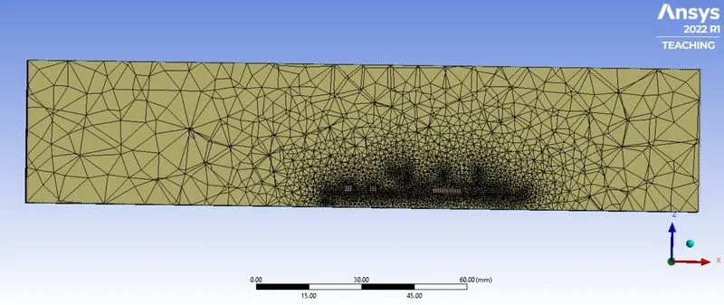
The first step into meshing should be to provide a name to each surface and component which was given as depicted in the below picture.
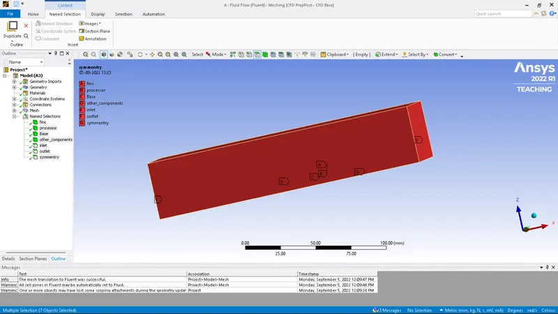
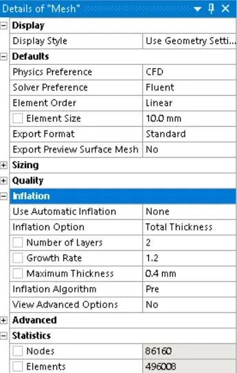
Element size for enclosure – 10mm
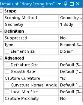
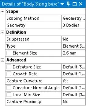
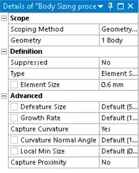
Body Sizing :
element size 0.6mm
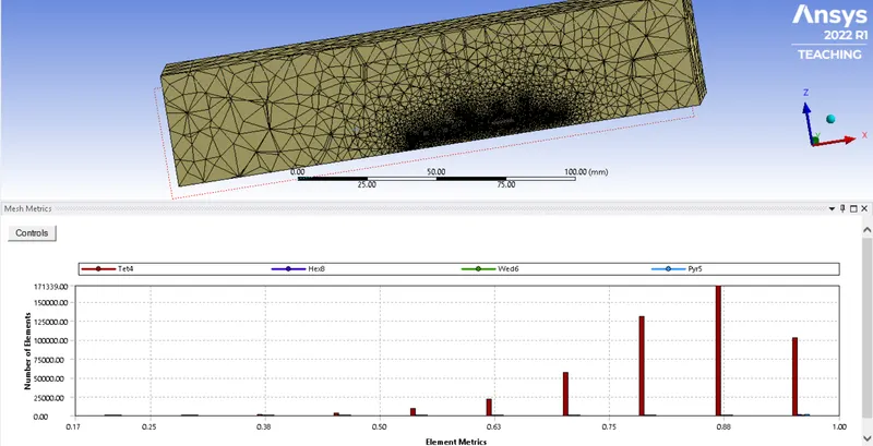
Mesh qulity
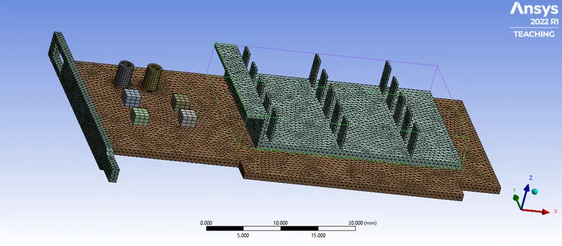
Final meshed model:
SETUP:
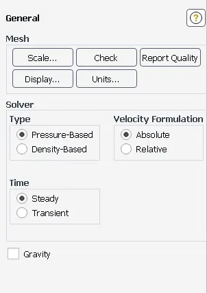
GENERAL:
- Type - Pressure based
- Velocity formulation – absolute
- Time – steady
MODEL:
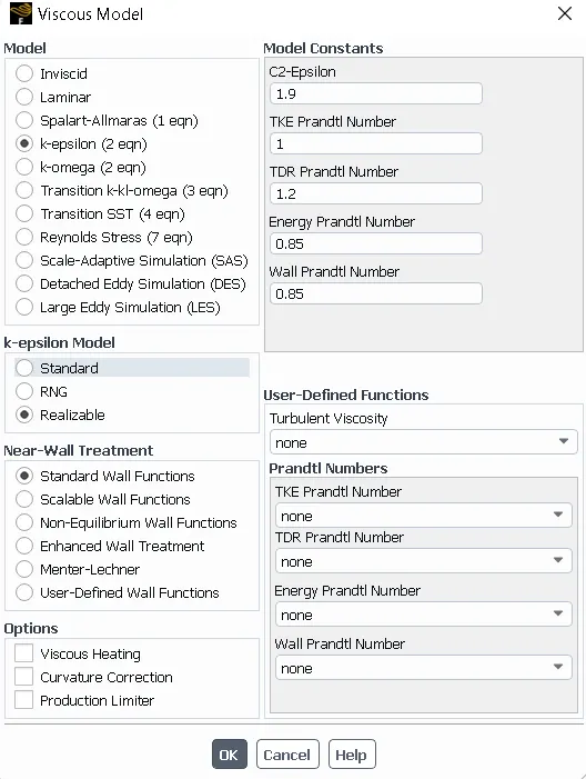
- Energy – on
- Viscous – realizable k-epsilon with standard wall function
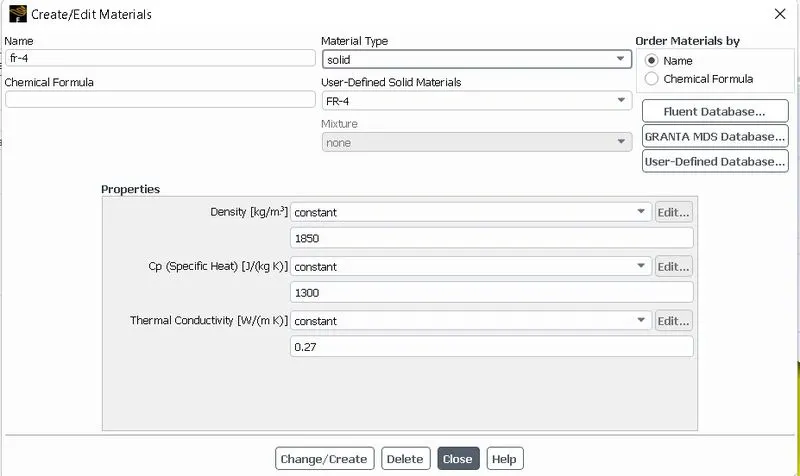
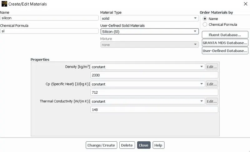
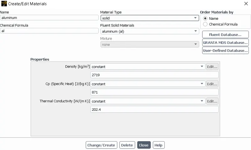
MATERIAL:
- Fluid – air
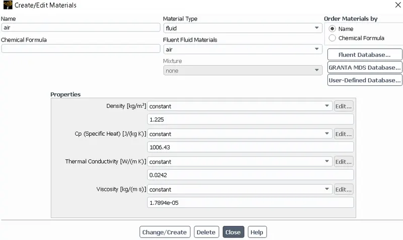
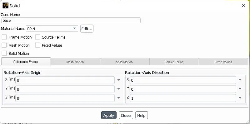
- Solid – Base – FR-4
Processor – silicon
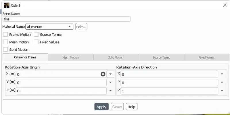
Fins – aluminum
CELL ZONE:
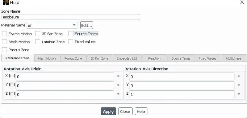
- Enclosure: fluid–air
- Graphics card base: solid – FR-4
- Graphics card fins: solid–aluminum
- Graphics card processor: solid–silicon
Source from processor – 156250000 w/m3
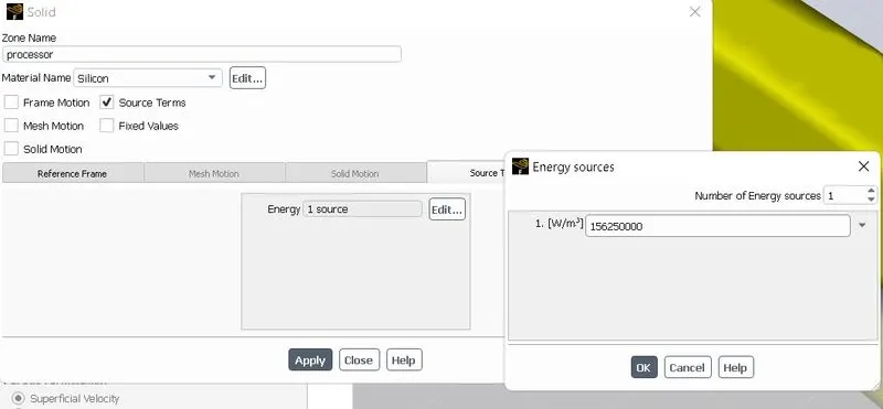
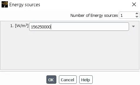
The processor is assumed as the only source of heat. The heat generated by the processor is calculated as:-
Graphics Card Power = 10W
Volume of the card = 8 x 8 x 1
`= 64mm^3 = 64e^(−9)m^3`
Heat generated `= P/V = 10 /(64 e^(− 9))`
`= 1.5625 e^8` `W/(m^3)`
BOUNDARY:
INLET:
- Velocity – Case 1 – 1m/s
Case 2 – 3m/s
Case 3 – 5m/s
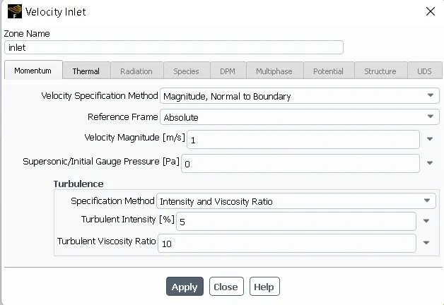
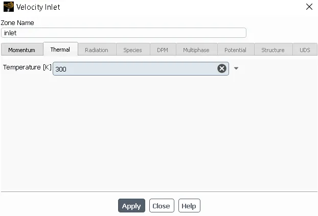
- Temperature – 300k
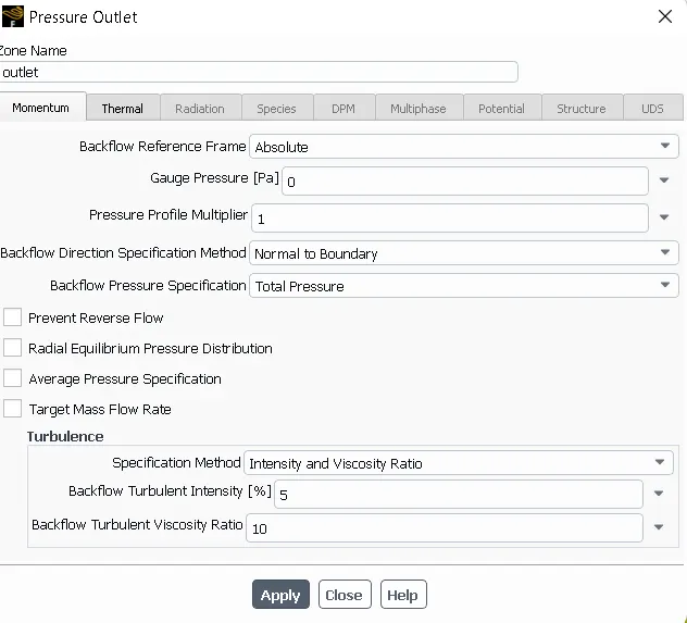
OUTLET:
Gauge pressure - zero
SYMMETRY WALL:

OTHER BOUNDARY:
Walls and interior type
INITIALIZATION:
Standard initialization
The simulation is run for 500 iterations.
RESULTS:
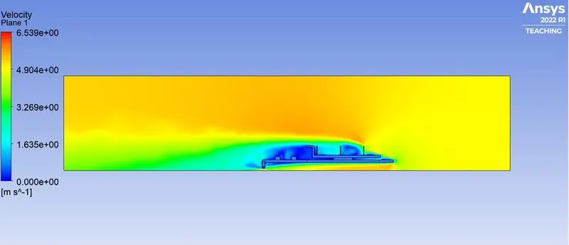
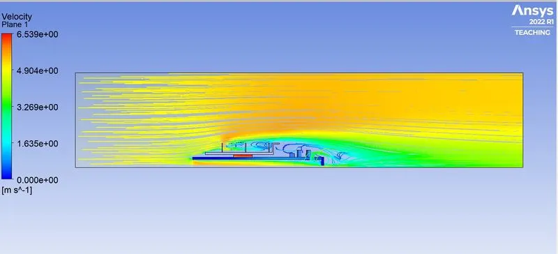
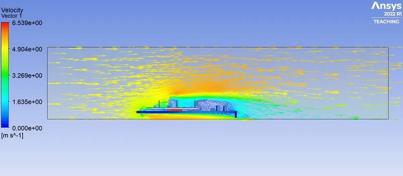
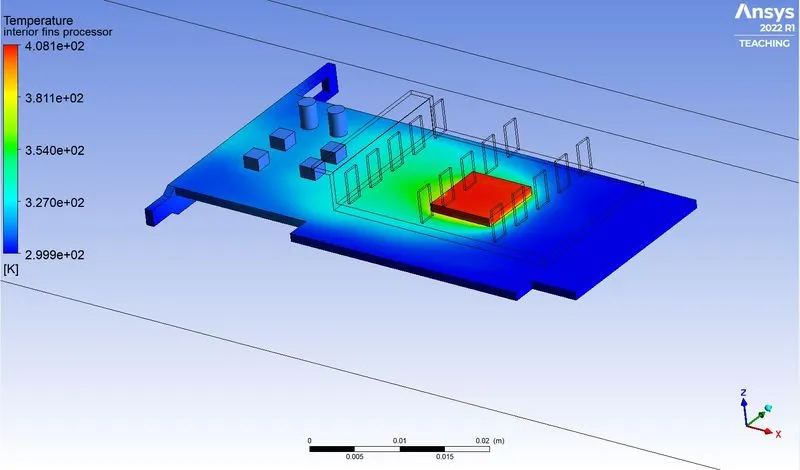
VELOCITY = 5M/S
RESIDUAL:
VELOCITY CONTOUR:
VELOCITY STREAMLINE:
VELOCITY VECTOR:
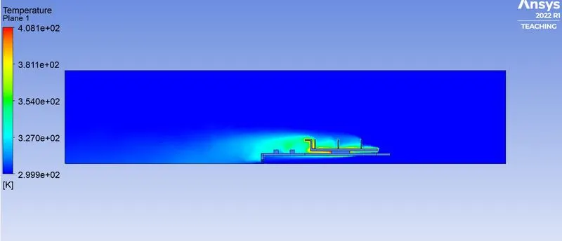
TEMPERATURE CONTOUR:
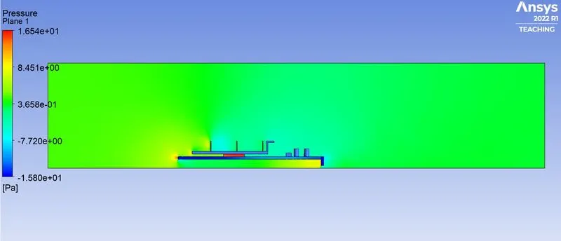
PRESSURE CONTOUR:
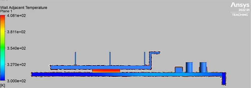
WALL ADJACENT TEMPERATURE:
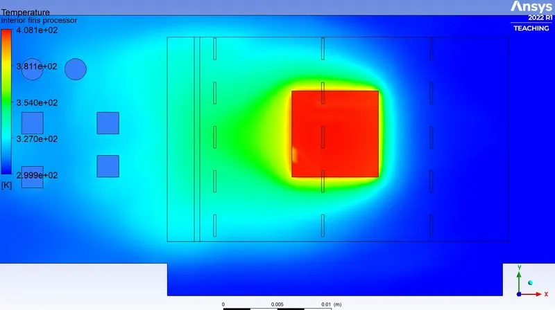
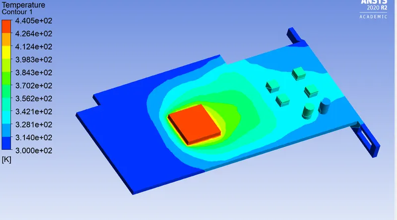
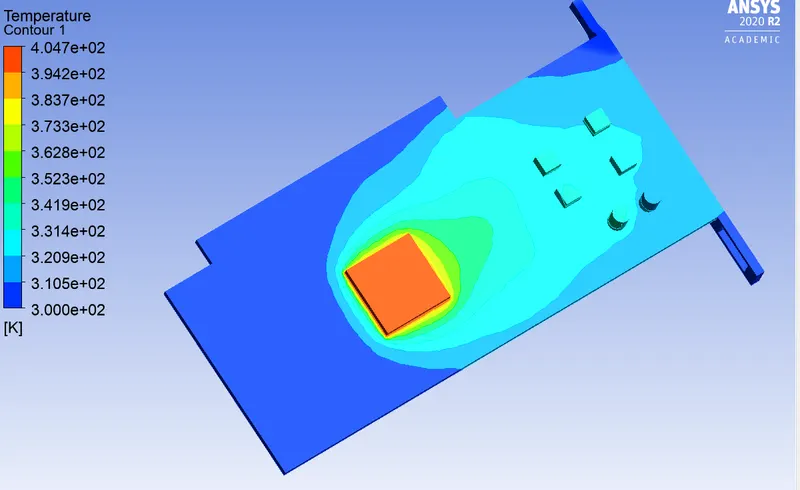
HOTSPOTS:
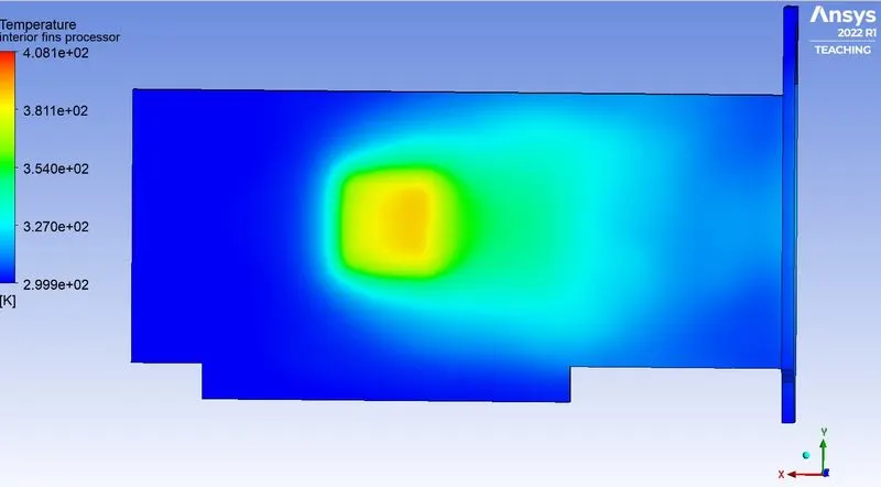
SIMULATIONS OUTPUT
| VELOCITY = 1m/s | VELOCITY = 3m/s | VELOCITY = 5m/s | |
| RESIDUALS | 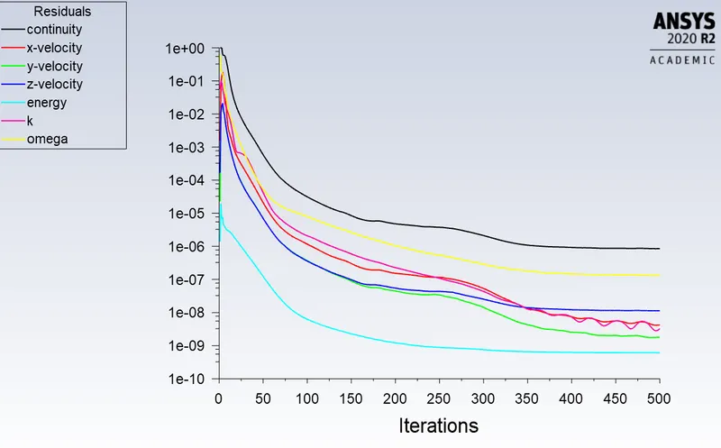 |
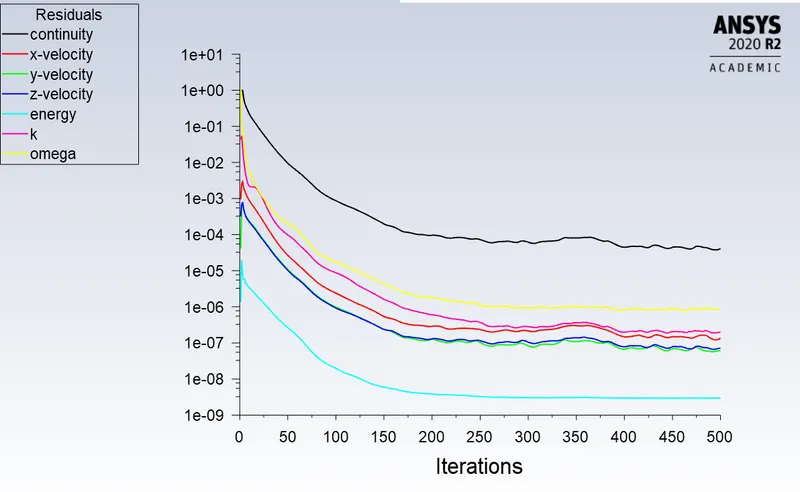 |
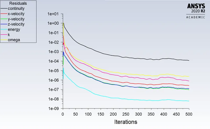 |
D. POST-PROCESSING
| VELOCITY = 1m/s | VELOCITY = 3m/s | VELOCITY = 5m/s | |
| Global Hotspot Region | 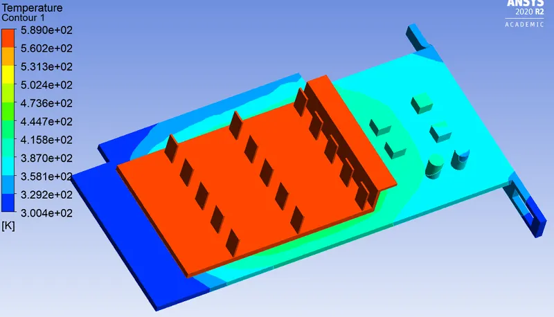 |
 |
 |
| Hotspot Around the Processor | 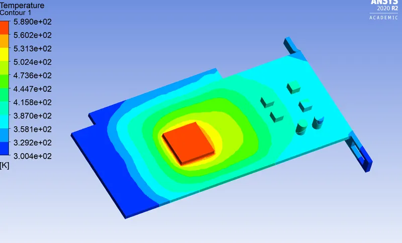 |
 |
 |
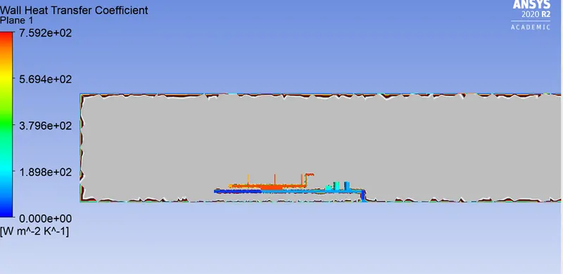
| Wall Heat Transfer Coefficient | 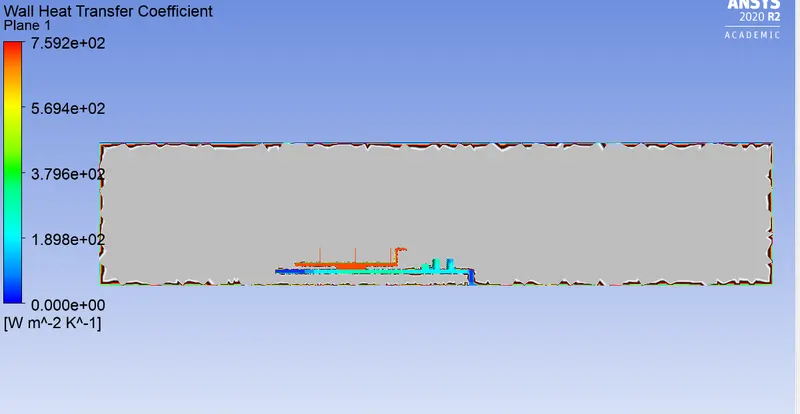 |
 |
 |
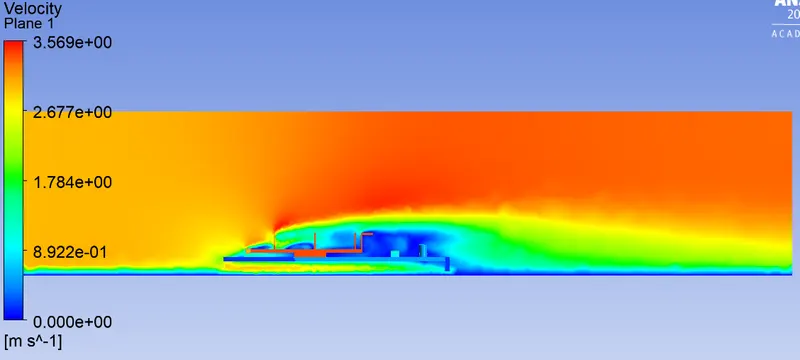
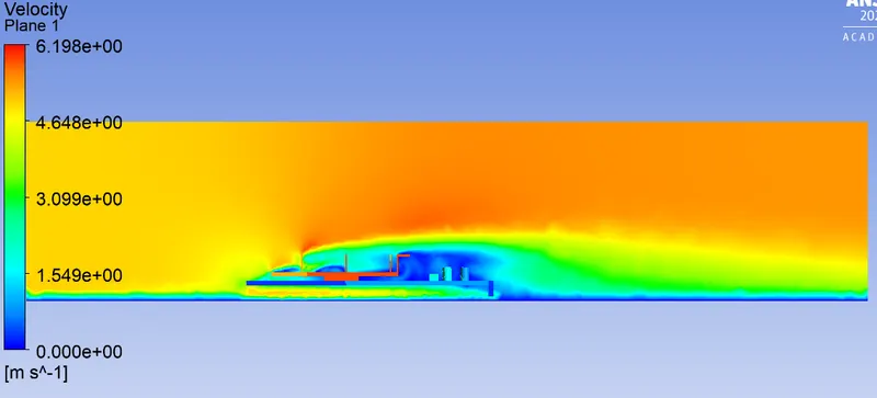
| Velocity Contour | 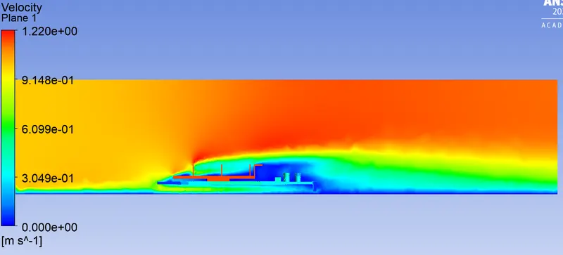 |
 |
 |
RESULTS
| Velocity | The temperature at Processor [k] | The temperature at Fins [k] | HTC at Fins |
| 1 | 587.18 | 580.28 | 256.94 |
| 3 | 438.78 | 431.88 | 258.47 |
| 5 | 402.95 | 396.20 | 262.49 |
CONCLUSION:
- As the velocity of incoming air increased the maximum temperature reached was decreased. This is due to the fact as air velocity increases, the heat transfer convective coefficient increases so heat transfer to the surrounding increases, and the temperature attained by the material decreases.
- Due to the recirculation of air at the rear face of the fin temperature is lower than the front face of the fin.
- For fast and better cooling the component's air velocity must be greater
- With an increase in velocity maximum conjugate heat transfer coefficient at the processor wall increases.