Week 6 - CHT Analysis on a Graphics card
AIM
- Analysis of steady-state conjugate heat transfer using a graphics card model
Objectives:
- Run the simulation by varying the velocity from 1m/sec to 5m/sec for at least 3 velocities and discuss the results.
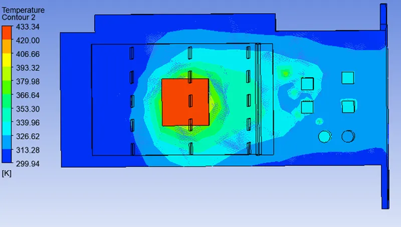
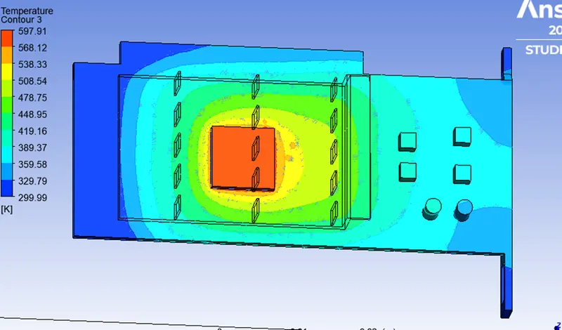
- Find out the maximum temperature and heat transfer coefficient attained by the processor.
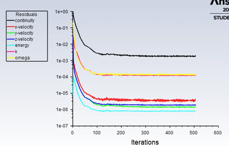
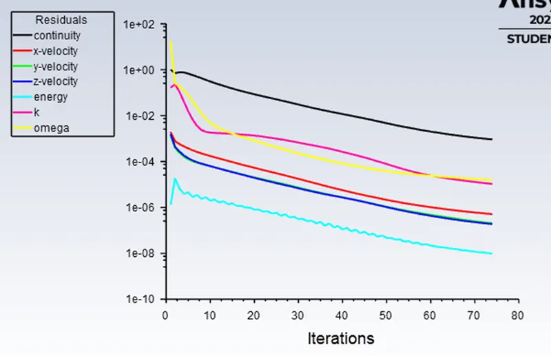
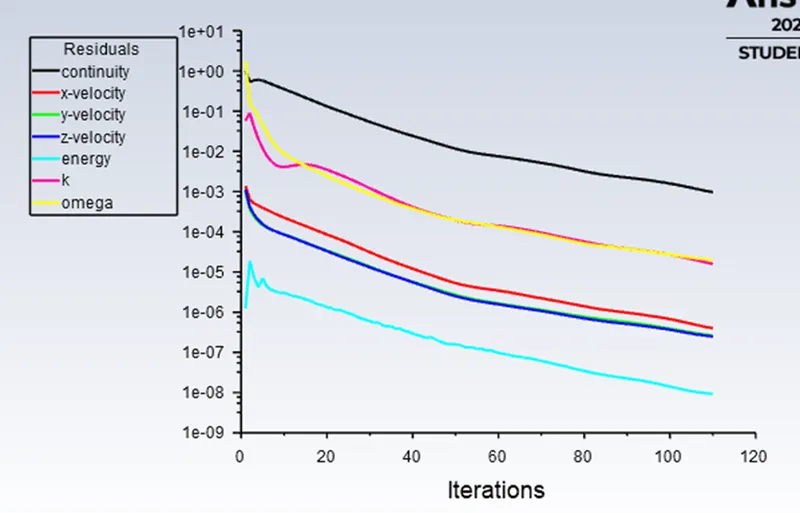
- Prove that the simulation has achieved convergence with appropriate images and plots.
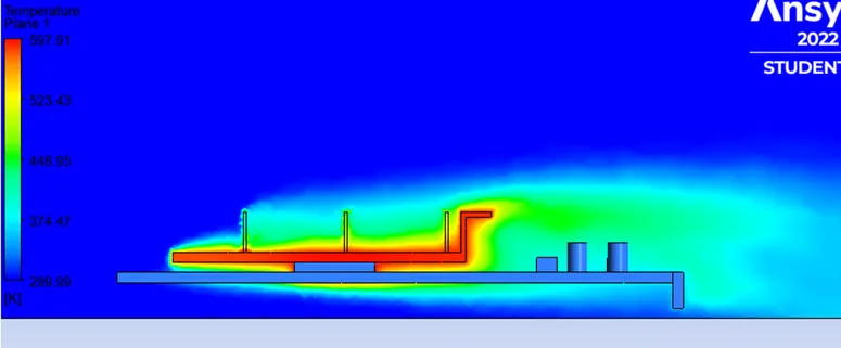
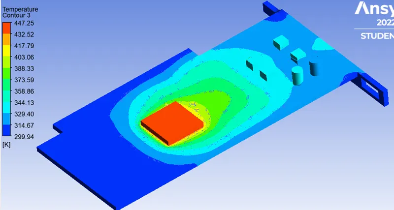
- Identify potential hotspots on the model.
Conjugate Heat Transfer Analysis (CHT):
- The conjugate heat transfer (CHT) analysis type allows for the simulation of heat transfer between solid and fluid domains by exchanging thermal energy at the interface between them.
- Conjugate heat transfer analysis can accurately predict heat transfer by simultaneous solving all the revenant solid and flow heat transfer processes.
Application:
- The simulation of heat exchangers.
- Cooling of electronic equipment.
- General – purpose cooling and heating systems.
- Conduction through solids.
- Free and forced convection in the gases/fluids.
- Thermal radiation.
Advantages:
- The CHT approach has an advantages over FE thermal analysis in that wall heat transfer coefficient and their local variations on surfaces are directly calculated with in the model rather than based on simplified empirical calculation.
- The CHT approach therefore has benefits for those applications where heat transfer is either non – uniform or difficult to calculate empirically.
Graphics card:
- Graphics card is a hardware which is used to increase the video memory of a computer, and make its display quality more high – definition.
- It makes the computer more powerful and gives it the capacity to do more high – level works. The quality of the image depends on the quality of the graphics card.
- It is very much important for gaming and video editing on a PC. Every game needs a graphics memory to start and it depends on the type of the game, and the requirements are mentioned on the game box.
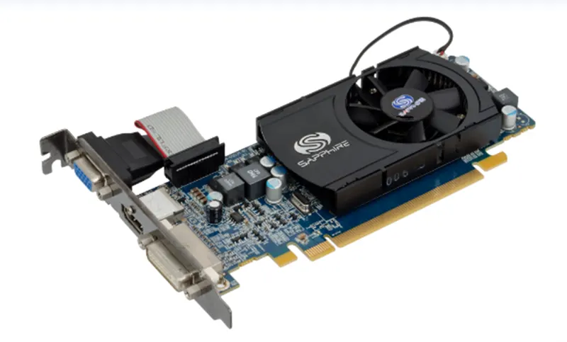
Model of graphics card we used for simulation:
GEOMETRY
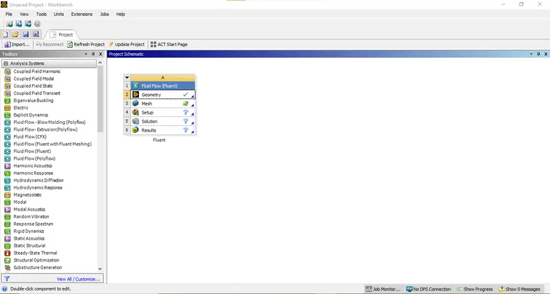
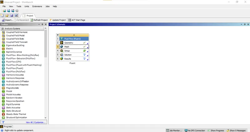
- Open ANSYS Workbench 2022R2 select Fluid Flow (Fluent) from Toolbox.
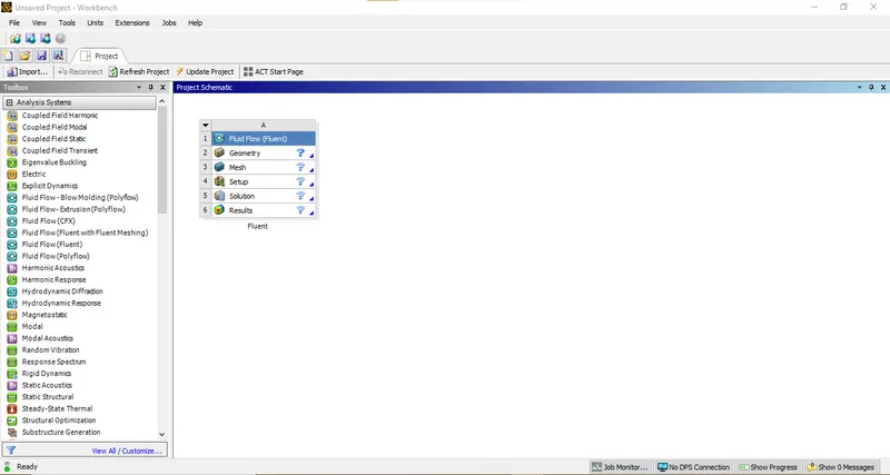
- Rename the file and left click Geometry and select New Spaceclaim Geometry.
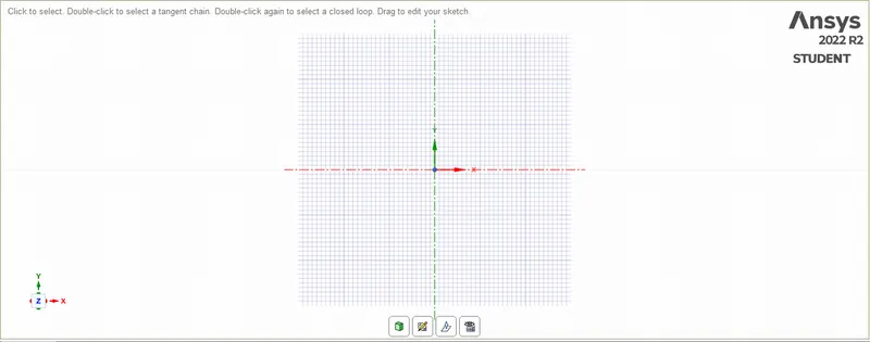
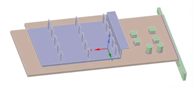
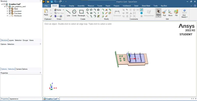
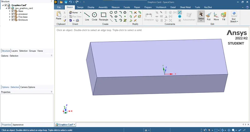
- Create the geometry as shown below using rectangle tool and create surface by using Fill option and rename the surfaces as solid and fluid. The created geometry is shown in the below figure.
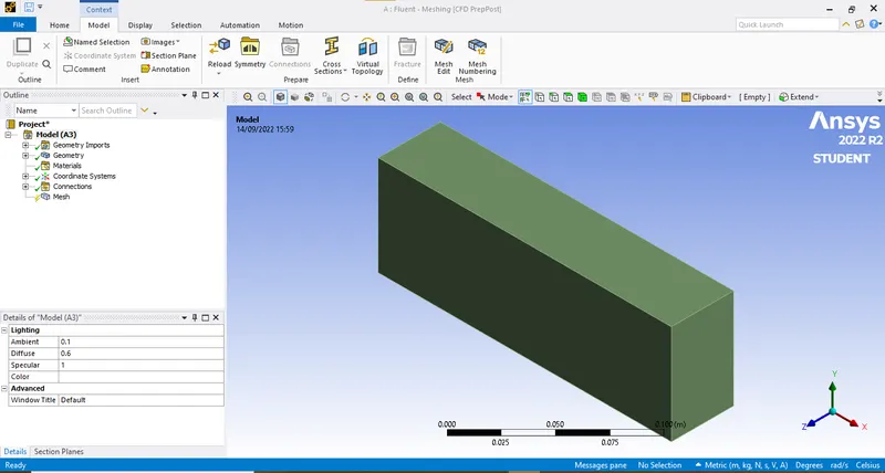
- Close SpaceClaim and double click on Mesh
MESH
It has four parts namely:
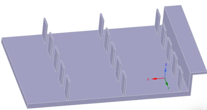
Fin:
These are placed above the graphics card processor to dissipate heat produced by the processor, Fins increase the surface area of contact with air this increase the amount of heat dissipation.
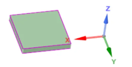
Processor:
- This is the main hardware in the graphics card that takes the input and gives desired to get best image quality.
- Image quality depends upon how powerful this processor is.
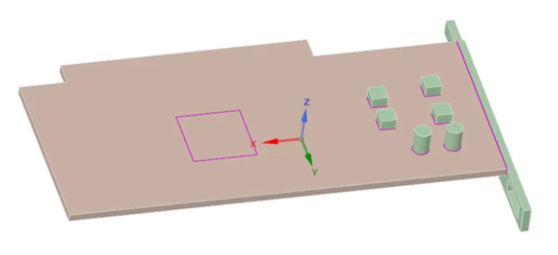
Base:
- This is where all circuit and other small electronic components are present it has less thermal conductivity compared to fines as a result most of the heat dissipation only occurs through FiN
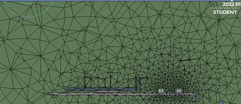
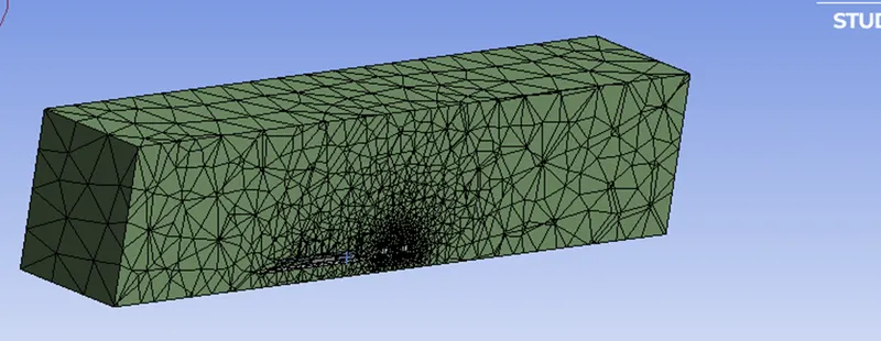
Base mesh:
- A basic mesh is generated using the standard values recommended by ANSYS.
- This meh is used to obtain an initial solution which will help us to determine the location where mesh refinement is required.
Element order: linear.
Element size: default.
Number of nodes: 12627.
Number of elements: 52375.
Simulation setup:
- Solver: steady state.
- Type: pressure based.
- Turbulence model: K – Omega (SST).
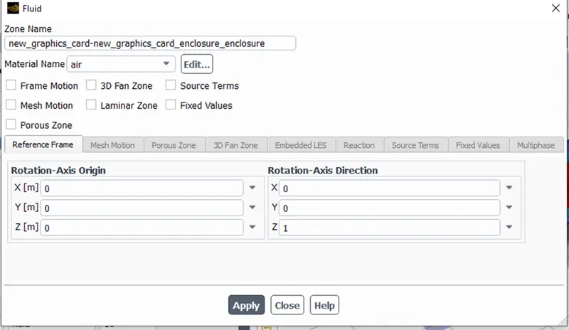
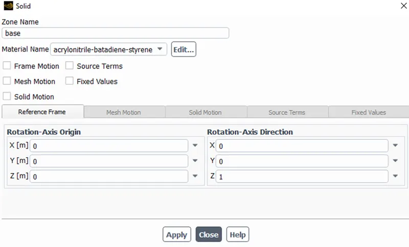
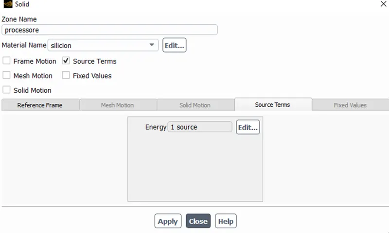
- Materials: different materials are used for each part, some of which are custom created.
|
Parts |
Material |
|
Enclosure |
air |
|
Fin |
Aluminum |
|
Processor |
Silicon |
|
Base |
Acrylonitrile butadiene styrene |
Air:
Acrylonitrile butadiene styrene:
Silicon:
Aluminum:
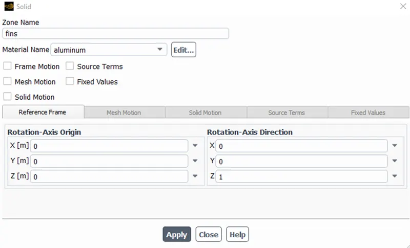
The processor is assumed as the only source of heat. The heat generated by the processor is calculated as:
Graphics card power = 10W.
Volume of the card = 64 mm3.
Heat generated = P/V = 156250000 W/m3.
Solution:
Temperature:
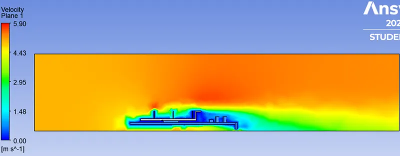
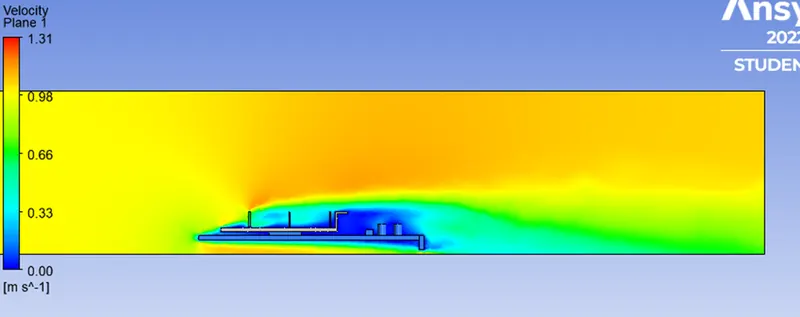
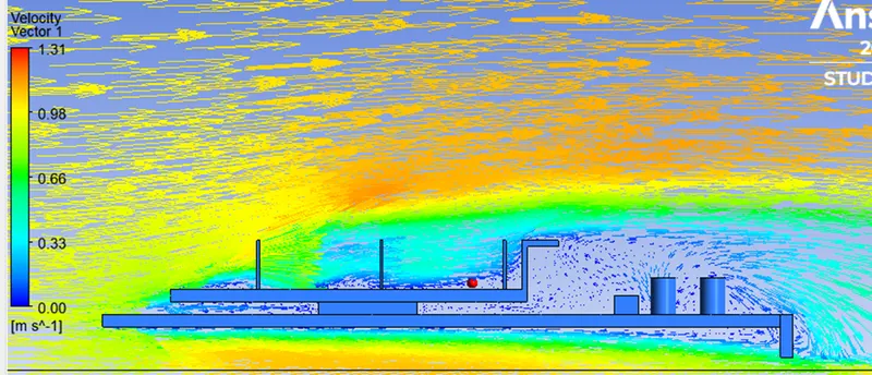
Velocity:
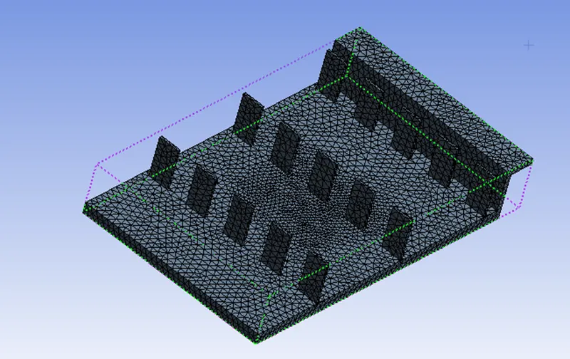
Refined mesh:
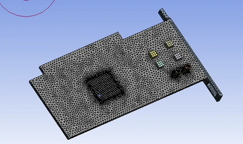
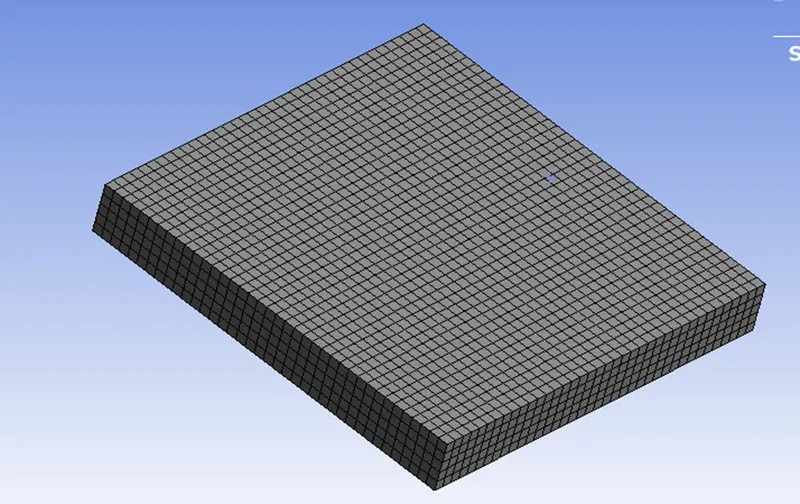
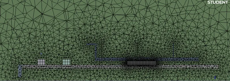
Mesh:
- Element order: linear.
- Element size: 0.003m
Body sizing (FIN):
- Element size: 0.0005m
- Curvature capture: yes.
Body sizing (PROCESSOR):
- Element size: 0.0002m
- Curvature capture: yes.
Body sizing (BASE):
- Element size: 0.0008m
- Curvature capture: yes.
Number of nodes: 91319.
Number of elements: 490667.
Simulation setup:
The simulation setup is the same as that selected for the initial mesh. Only the output of the simulation will changes because of the changes in the inlet velocities.
Velocity at 1m/s
Residuals:
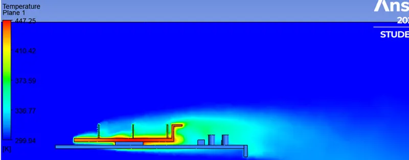
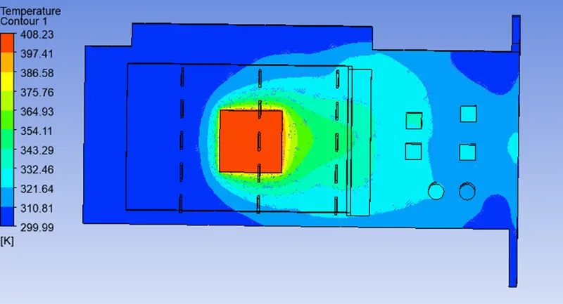
Temperature contour:
Temperature plane:
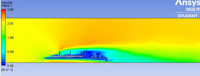
Velocity plane:
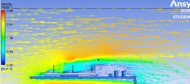
Velocity vector:
Velocity at 3m/s
Residuals:
Temperature contour:
Temperature plane:
Velocity plane:
Velocity vector:
Velocity at 5m/s
Temperature contour:
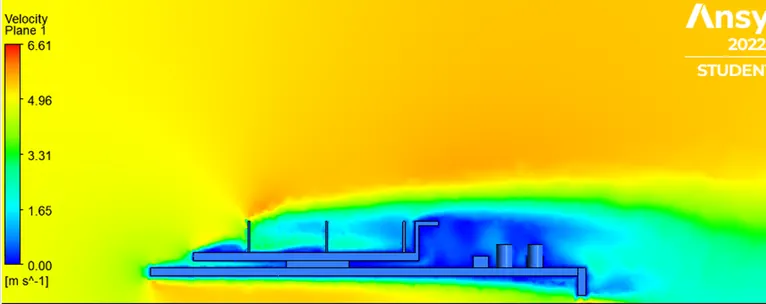
VELOCITY PLANE
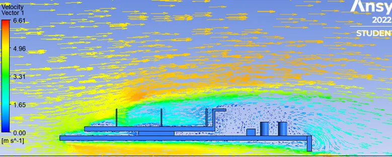
Velocity vector:
CONCLUSION
- As the number of elements increases the accurate results of temperature distribution is obtained.
- From the above table, it is fairly notable that, the net temperature of components of graphics card decreases with an increases in inlet velocity.
- Hence it can be inferred that a higher inlet velocity results in better cooling and lower the average temperature thus keeping the components safe from damage.
- It can be observed that the temperature of components increases as the inlet velocity decreases from 5m/s, to 1m/s, also proving that higher velocity results in better cooling.