Week 6 - CHT Analysis on a Graphics card
Introduction : - CHT means Conjugate Heat Transfer. It is defined as transmission of heat between solid and fluid medium. The primary mode of heat transfer in solid is conduction and primary mode of heat transfer in fluid medium is convection. Here we are going to analysis two cases.
Case1: CHT Analysis in Graphic card (General mesh)
Case2: CHT Analysis in Graphic card (Finer mesh)
Example :
HVAC, Heat Exchanger, Tank, Internal Combustion Engine, Heat Sink, Boiler, Reactor, Heat pipe,Turbocharger.
Heat transfer in a solid - Conduction : Diffusion of heat due to temperature gardients in solids. A measure of the amount of conduction for a given gradient is heat conductivity. Conduction is described by Fourier's Law defining the conduction heat flux,q, proportional to the temperature gradient.
Heat transfer in a fluid - Convection : When heat is carried away by moving fluid. The flow can either be caused by external influences, forced convection or by buoyancy forces, natural convection.
Due to the fluid motion, there are three contributions to the heat transfer:
Convective contribution: Depending on the properties of the fluid and its region of flow, the domination of conduction and convection varies.
Viscous effects: Due to the fluid flow, the viscosity creates heat. This effect is often neglected due to its negligible value but should be taken into account for high-velocity cases.
Density effects: When the density become related to the temperature, the domain will have different densities at different locations based on the temperature distribution. This variation in density can cause the compression which in turn generates the heat.
Applications:
Starting from simple example in the 1960's teh conjugate heat transfer methods have become a more powerful tool for modelling and investigating natural phenomena and engineering systems in different areas ranging from aerospace to nuclear reactors to thermal interaction in meteorology, and from relatively simple units to multistage, non-linear processes. A detailed review of more than 100 example of conjugate modelling selected froma list of 200 early and modern publication shows that conjugate methods are now used extensively in a wide range of applications.
Steps to analysis of Graphic card:
- Geometry
- Meshing
- Set up
- Solution
- Results
Case 1: CHT Analysis in Graphic card
- General mesh
Geometry:
- Importing the model
- Share topology
1. Imorting the model:
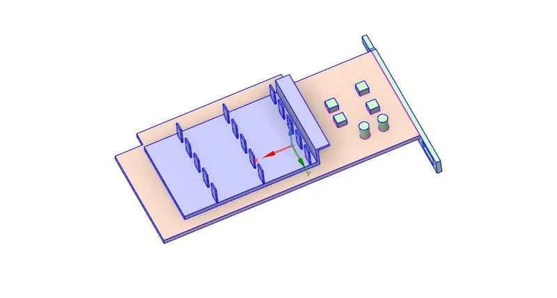
The first step is to import the solid Graphic card to the Spaceclaim. The enclosure is already there in the model so that we do not need to create the enclosure
Graphic card:
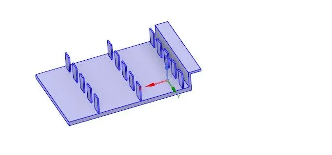
Fins :
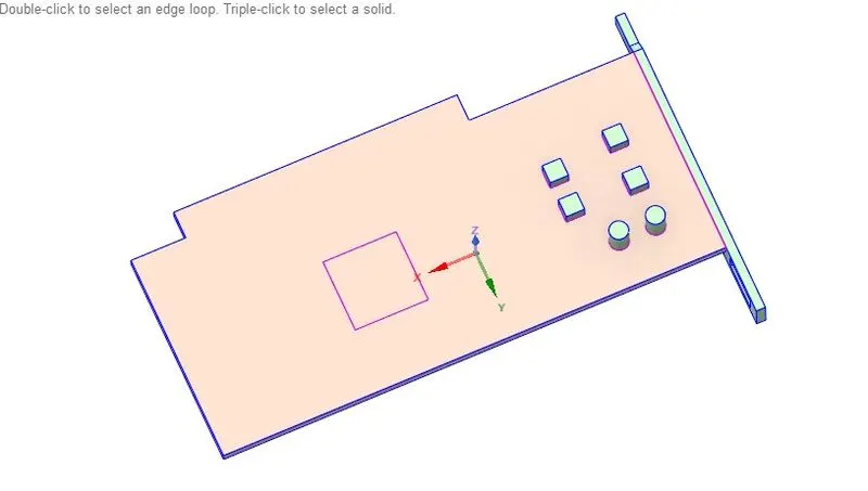
Base :
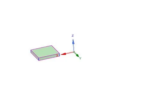
Processor:
;
Graphic card with enclosure:
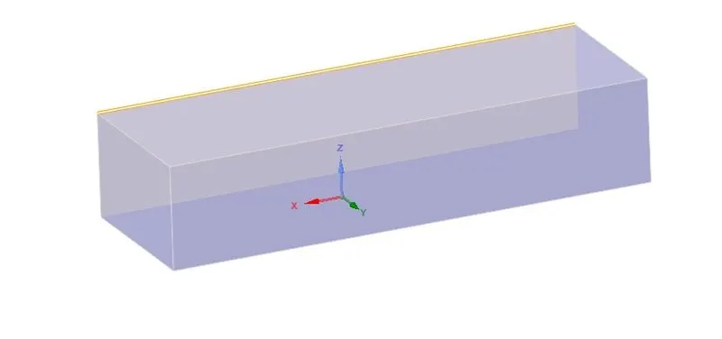
2. Share Topology:
Share topology is defined as the sharing the information. Here, the information is shared between the enclosure the Graphic card.
Meshing:
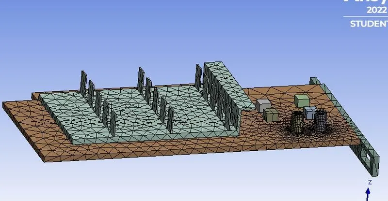
1. Before generating a mesh let's name the different components of the graphic card so it is easier to find them while setting up fluent.
2. Base, processor and fins are basic name selection which will help us in the simulation.
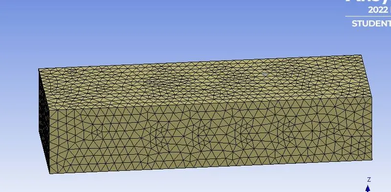
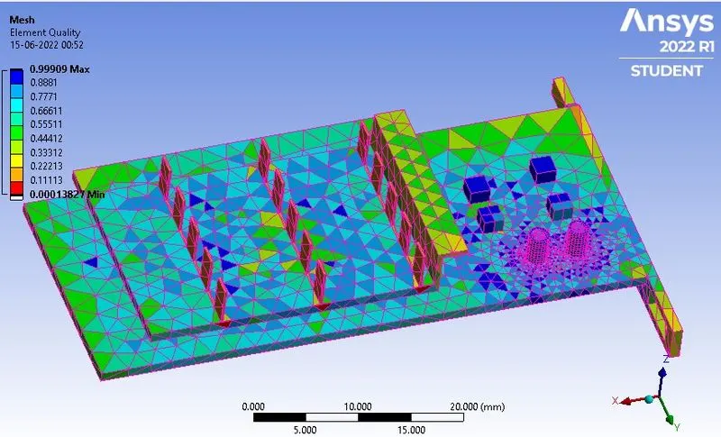
3. Click generate mesh to create a base mesh, body sizing can be applied for the solid components.
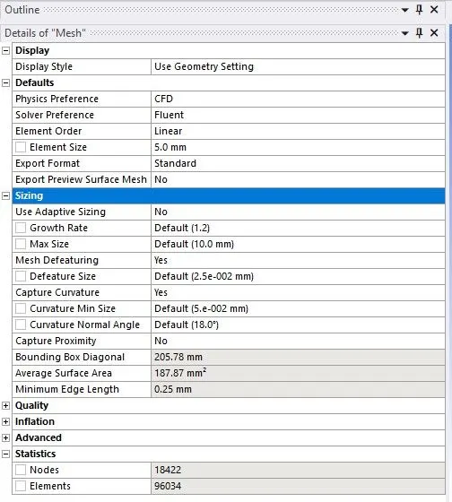
4. After,creating a body sizing for 3 components, generate mesh as that it is considered as a base mesh having more than 1 lakh elements which helps us in finding accurate solutions.
5. After creating the mesh, exit mesh setup to simulate the fluent.
Fluent setup:
Setting up the physics :
Setting up the physics for CHT analysis on a graphics card in ANSYS fluent
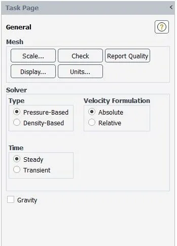
- For this case we are going to use pressure-based steady state solver.
- Velocity formation - Absolute
Model setup
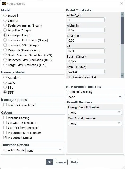
- Energy

- Viscous -k- omega
Materials :
We are using different materials for all the components
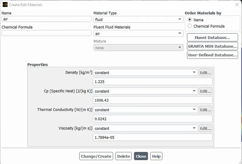
For fluid : Air
- Density = 1.225 kg/m^3
- Viscosity = 1.7894e-5 kg/ms
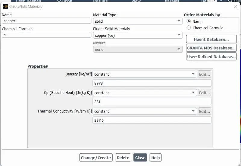
For Fins : Copper
- Density = 8978 kg/m^3
- Specific heat = 381 j/kg-k
- Thermal conductivity = 387.6 w/m-k
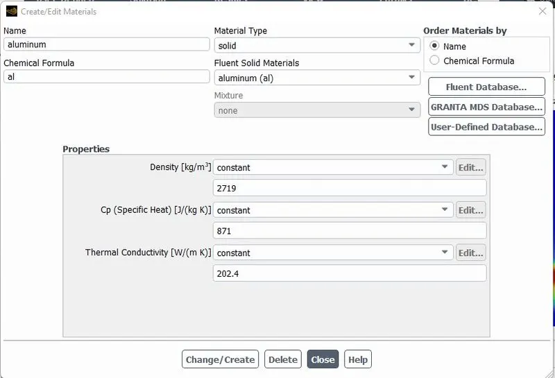
For Processor : Aluminum
- Density = 2719 kg/m^3
- Specific heat = 871 j/kg-k
- Thermal conductivity = 202.4 w/m-k
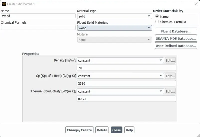
For Base : Wood
- Density = 700 kg/m^3
- Specific heat = 2310 j/kg-k
- Thermal conductivity = 0.173 w/m-k
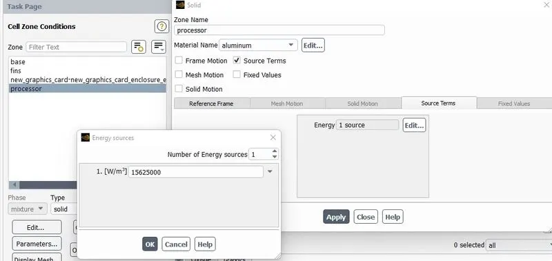
Setting up the sourse terms :
For this case we consider that, our processor is a source terms and it generating heat.
So, for setting up the sourse term go to Zones - cell zones- and click on the processor for editing which is in the solid.
After select the material to aluminum and click on the source term to enabled it and set the energy source to 1.
Calculation for the Energy source:
Dimension of the processor is going to be as per giving window 0.008*0.008*0.001 = 64*10e-9
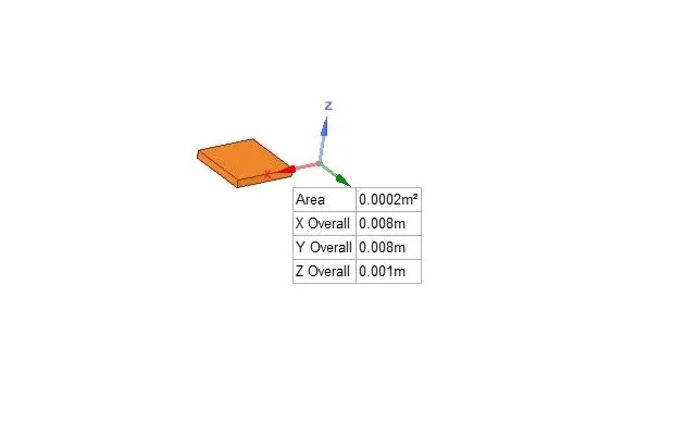
Graphics card power = 10W
volume of the card = 0.008*0.008*0.001 = 64e-9 m^3
Heat generated = P/V = 10/64e-9
So, Energy produced by the processor is 15625000 w/m^3.
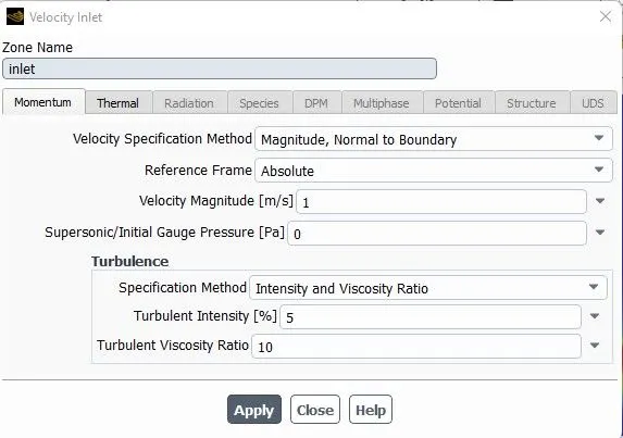
Inlet
- Air is used as a fluid
- Velocity = 1m/s
- Temperature = 300k
Oulet
Pressure = Gauge pressure (0 Pa)
Results :
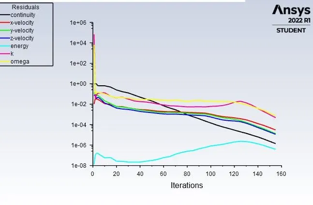
As per the mesh size provided before
Residuals
Maximum Temperature :
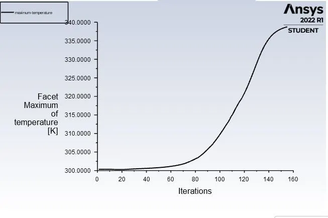
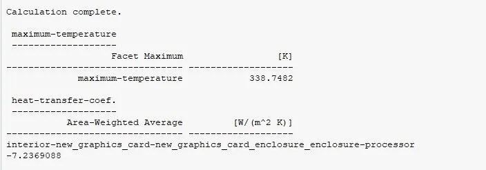
Values of Maximum temperature and Heat transfer coefficient
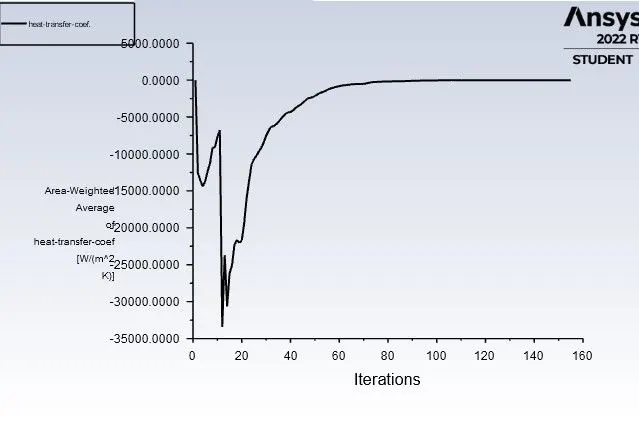
Heat Tansfer coefficient :
2. Refined Mesh
At Velocity = 3 m/s
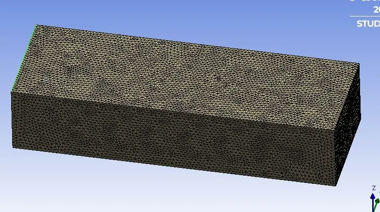
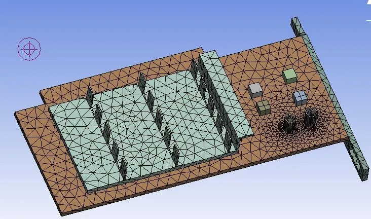
Here we can see the mesh detail given below :
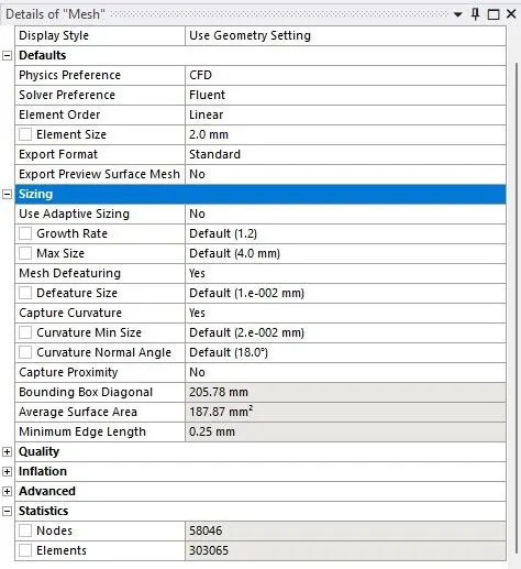
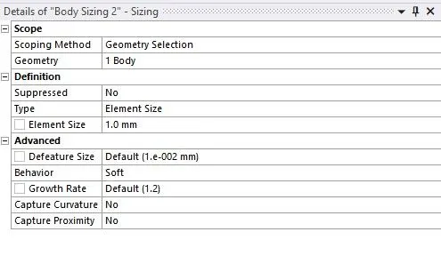
Body sizing at Fins
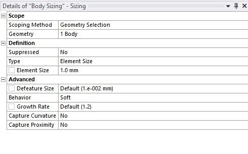
Body sizing at Processor
Enclosure and graphic card :
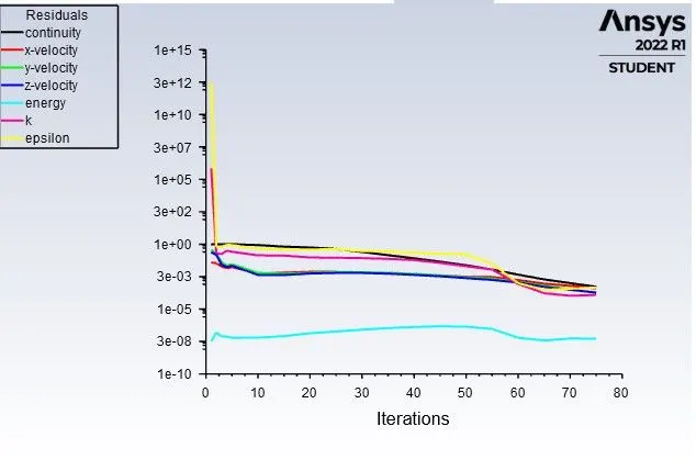
Residuals
Maximum Temperature
Heat transfer coefficient
Values of Maximum temperature and Heat transfer coefficient
3. Refined Mesh
At Velocity = 5 m/s
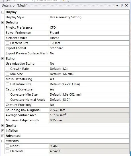
Here we can see the mesh detail given below :
Mesh
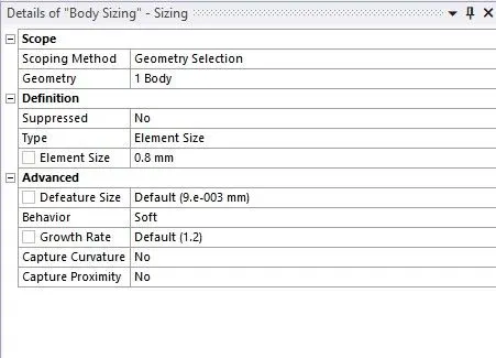
Body sizing at Fins
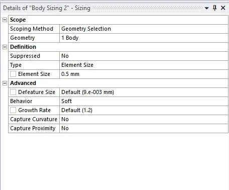
Body sizing at processor
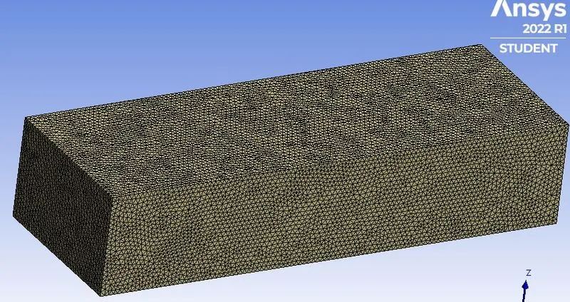
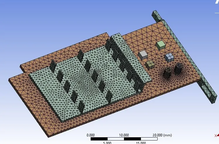
Enclosure and graphic card :
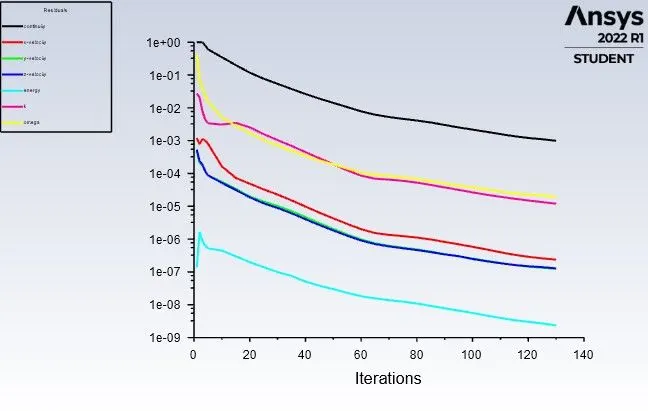
Residual
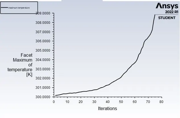
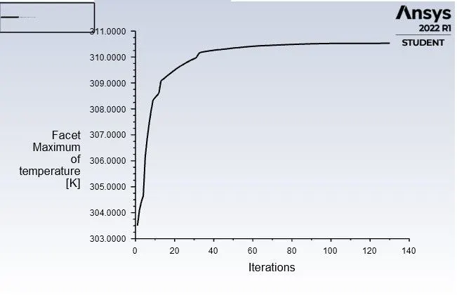
Maximum Temperature :
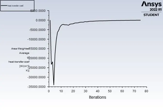
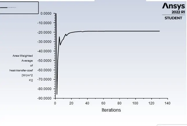
Heat transfer coefficient
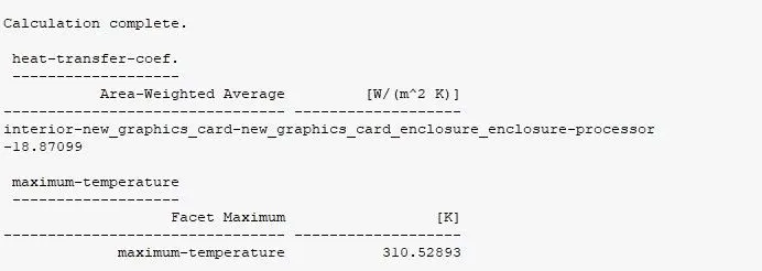
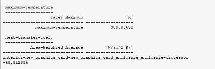
Values of Maximum temperature and Heat transfer coefficient
Post processing :
For 1m/s velocity
The backside of the circuit (backside hotspot)
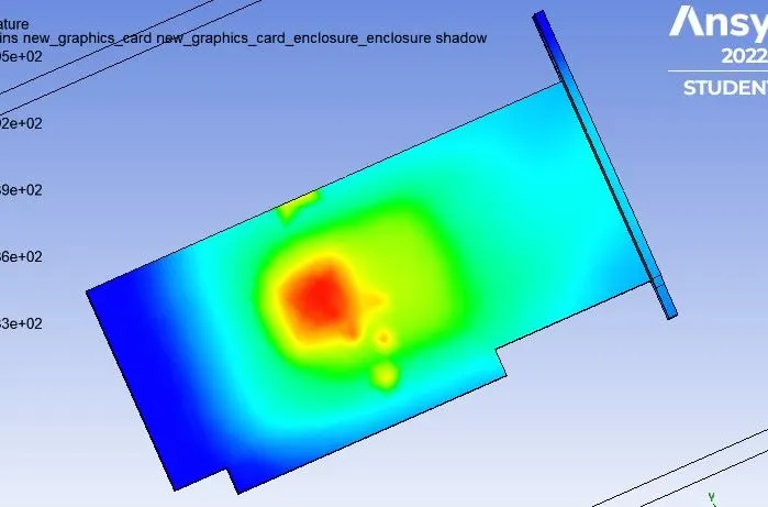
Upperside of the fin base and fins (upfront hotspot)
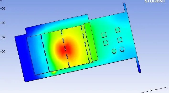
Velocity contour
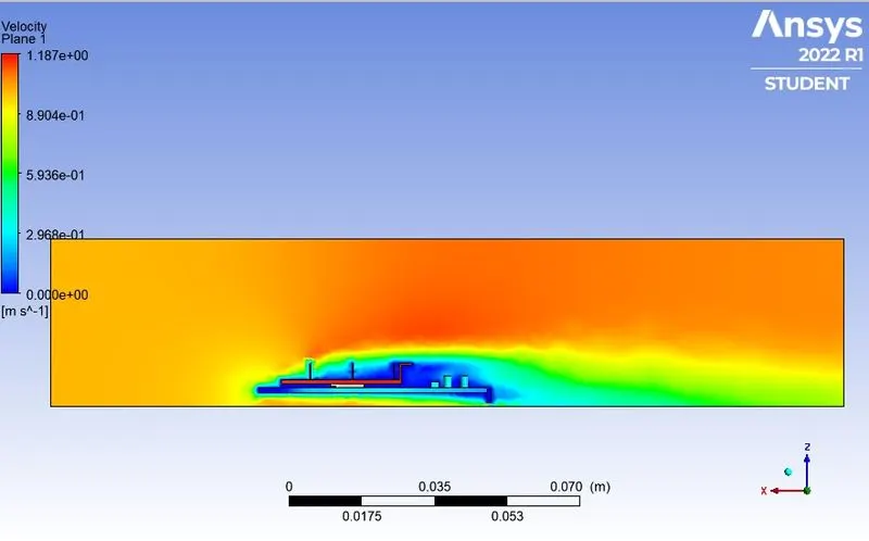
Temperature contour
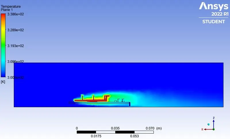
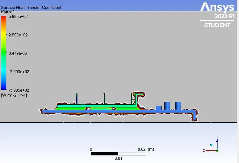
Surface Heat Transfer coefficient
For 3m/s velocity
For the 3m/s the heat transfer coefficient is showing high on the last component attached to the base plate because the velocity is high there.But for the heat dissipaton, we need the high HTC near the fin and base plate area. Therefore,those components can be ignored and the fin processor and base plate only considered to get proper heat transfer coefficient.
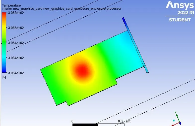
The backside of the circuit (backside hotspot)
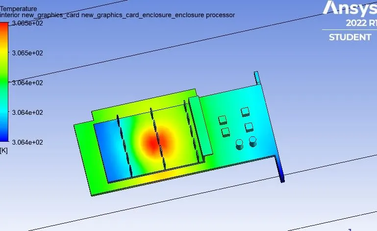
Upperside of the fin base and fins (upfront hotspot)
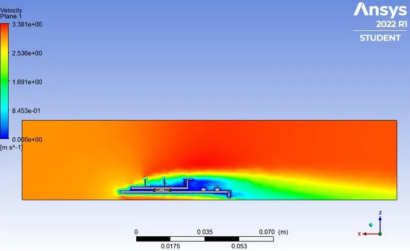
Velocity contour
Temperature contour
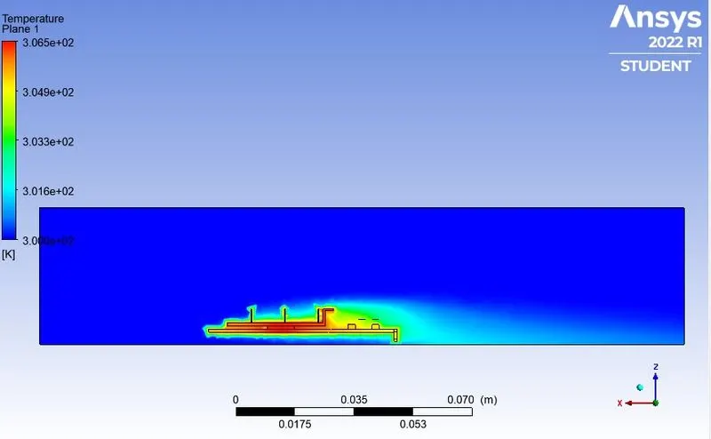
Surface Heat Transfer coefficient
For 5m/s velocity
The same thing is happening for the input velocity 5m/s we got the higher heat transfer coefficient near the boundary of the finsin the first row because the velocity is increasing near the boundary of the fins.
The backside of the circuit (backside hotspot)
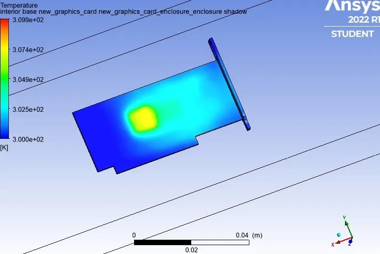
Upperside of the fin base and fins (upfront hotspot)
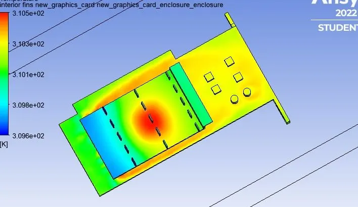
Velocity contour
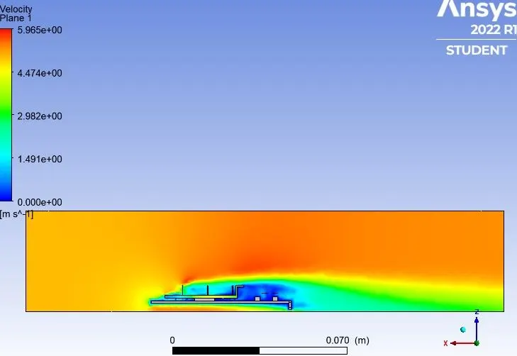
Temperature contour
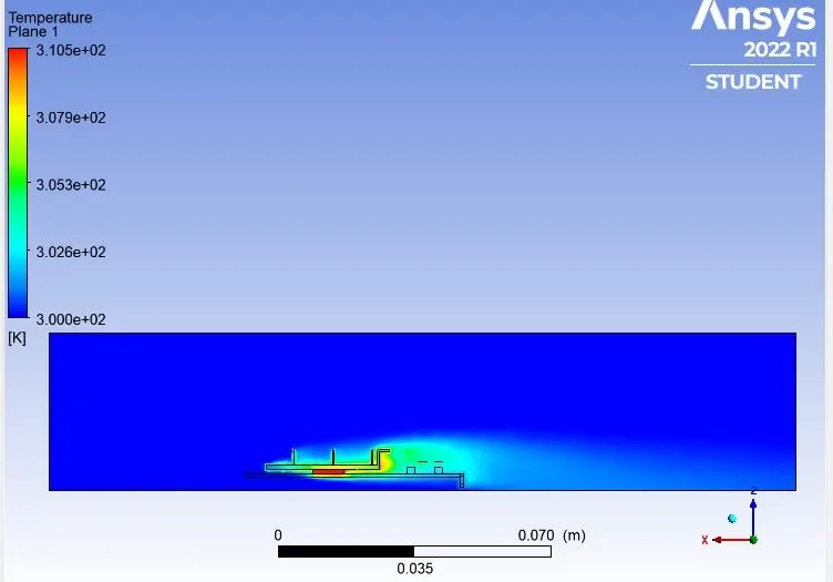
Surface Heat Transfer coefficient
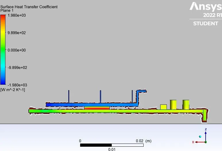
Final observations :-
| Simulation No |
Inlet Velocity (m/s) |
Mesh Size (mm) |
No. of Nodes | No. of Elements | Maximum Temperature (k) |
Heat Transfer coefficient (W/m^2 K) |
| 1. | 1 | 5 | 18422 | 96034 | 338.7482 | 7.2369088 |
| 2. | 3 | 2 | 58046 | 303065 | 310.52893 | 18.87099 |
| 3. | 5 | 1.8 | 90469 | 485467 | 308.85632 | 48.812654 |
Conclusion :
1. As the number of elements increases the accurate results of temperature distribution is obtained.
2. Hence, it can be inferred that a higher inlet velocity results in better cooling and lower the average temperature thus keeping the component safe from damage.
3. Furthermore, it can be observed that the temperature of components increases as the inlet velocity decreases from 5m/s to 1m/s , also proving that higher velocity results in better cooling.
4. For the turbulent models, we have to take care of the assumptions and the boundary conditions you put in the program. The mesh is a very important parameter to get nice results so we have to refine it in teh important place of our drawing.
5. Mesh/grid dependency test is very important to get confidence over results.