Week 6 - CHT Analysis on a Graphics card
INTRODUCTION:-
1. Conjugate Heat Transfer (CHT)
Conjugate heat transfer is defined as the heat transfer between two domains by exchange of thermal energy. For a
system the thermal energy available is defined by its temperature and the movement of thermal energy is defined
by its heat flux through the outer walls. Heat transfer in solid happens through conduction and walls by convection
and in liquid phase through convection.
CHT provides the temperature prediction and the hotspot regions at the solid-fluid interface and we can also predict
the heat transfer accurately for example- Conduction through solids, convection through fluid, and thermal
radiation. It also provides the velocity and pressure distribution of fluid moving inside the solid. We can also use CHT
in design optimization for improvement for heat transfer and cooling capacity.
2. A video card (also called a graphics card, display card, graphics adapter, or display adapter) is an expansion card
that generates a feed of output images to a display device (such as a computer monitor). Most video cards are not
limited to a 6-inch simple output. Their integrated graphics processor can perform additional processing, removing
this task from the central processor of the computer.
Modeling approach :-
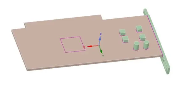
CAD clean up/Pre-process-SpaceClaim - Import the graphic card geometry which we have got into the SpaceClaim.
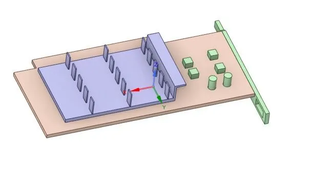
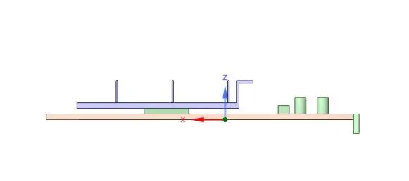
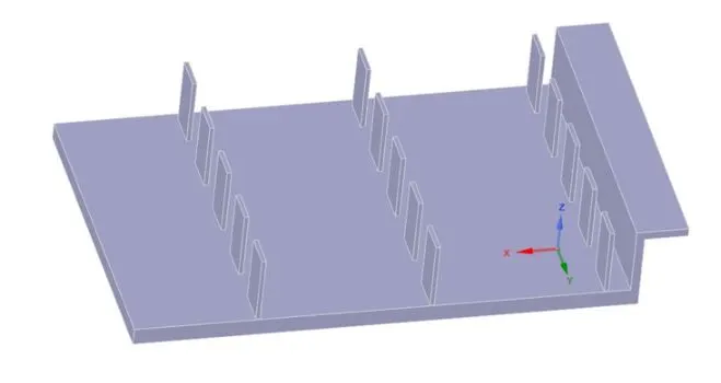
We can analyze each and every part of the graohic card like
FINS
Processor
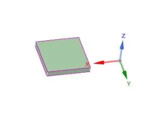
base
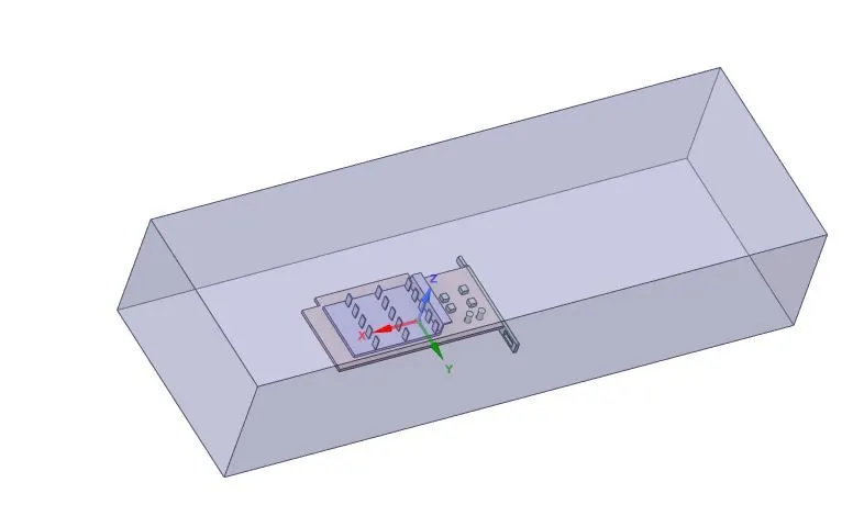
Now Create the enclosure around the graphic card
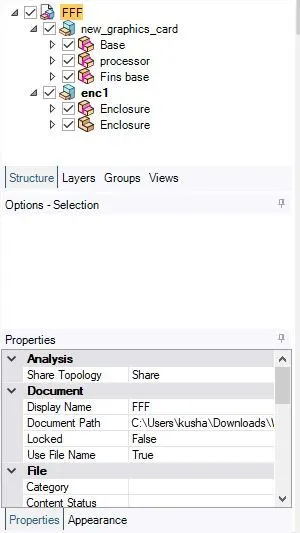
Topology is kept to share.
Meshing :-Apply the certain elements size . Provide the named selection accoradigly. Further we can refine the mesh by giving the sizing. And then update the mesh.
Setup :- In this section, we set up the steady simulation. Turbulance model (kω-SST)is applied for simulation. Turn on energy equation. Now I have to add the materials which are used for fins , base and processor. Apply the cell zone condition for fin , base and processor of the graphic card. Apply boundary condition velocity inlet.
Certain No of iteations are set for simulation.
Solution :- we can see the temperature distribution on the graphic card.
Set up for Geometry/ CAD modeling into SpaceClaim:-
Import the graphic card geometry which we have got into the SpaceClaim.
Now Create the enclosure around the graphic card
Topology is kept to share.
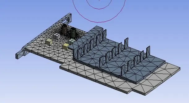
Meshing :- (Base simulation)
Apply the elements size as default provided by the Ansys . Provide the named selection accoradigly.
Total number of elements = 82402
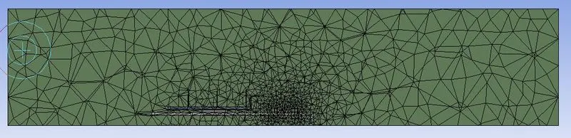
Mesh metric :-
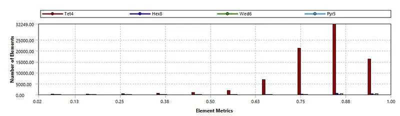
Here we can see that most of the elements are having higher quality in the range of 75% - 95%
Name selection :-
inlet
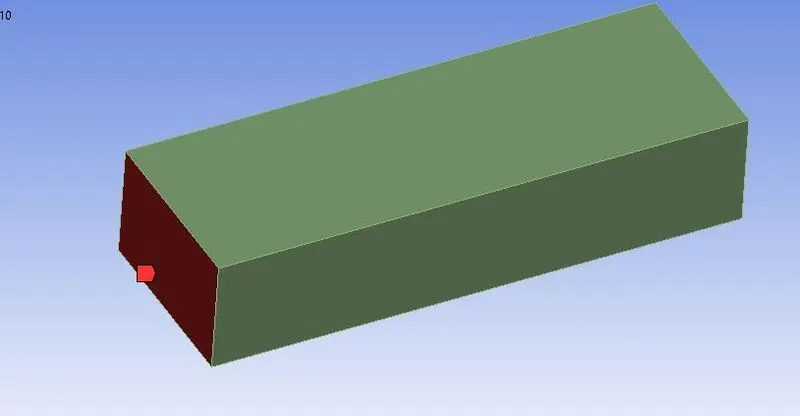
outlet
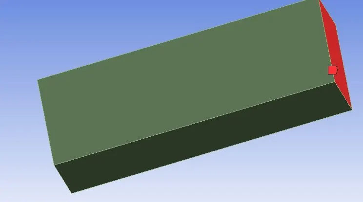
symmetry
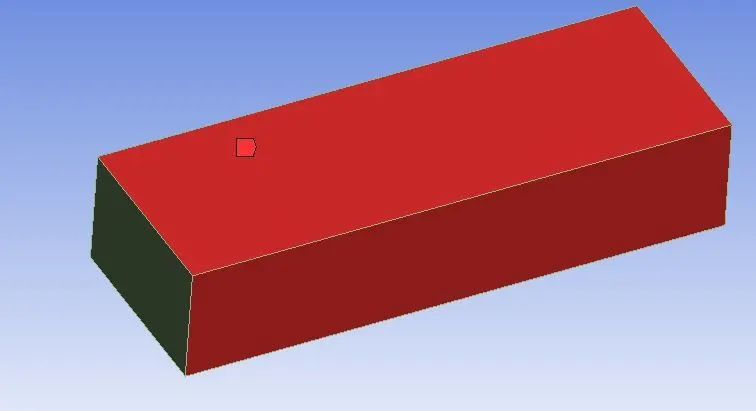
Base
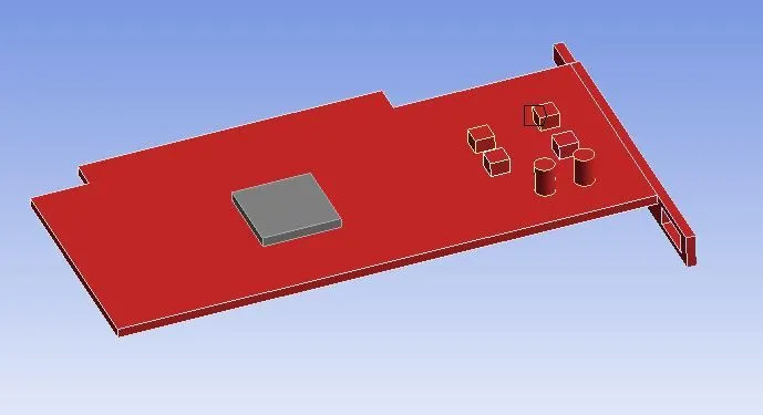
Finn-wall
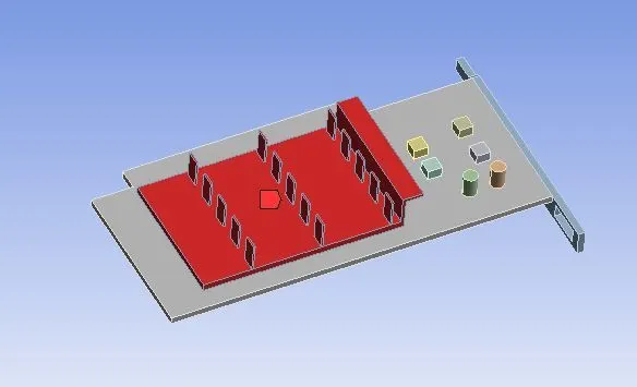
processor
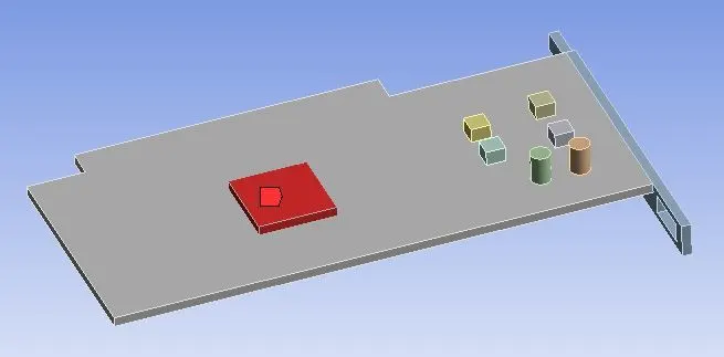
Setup :-
I set up the steady simulation. Turbulance model (kω-SST)is applied for simulation. Turn on energy equation.
Now I have to add the materials which are used for fins , base and processor.
Material properties:-
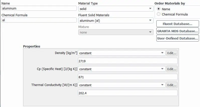
FINS - Aluminium is used for fin.
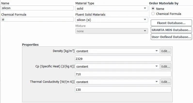
Processor - Silicon is used for processor.
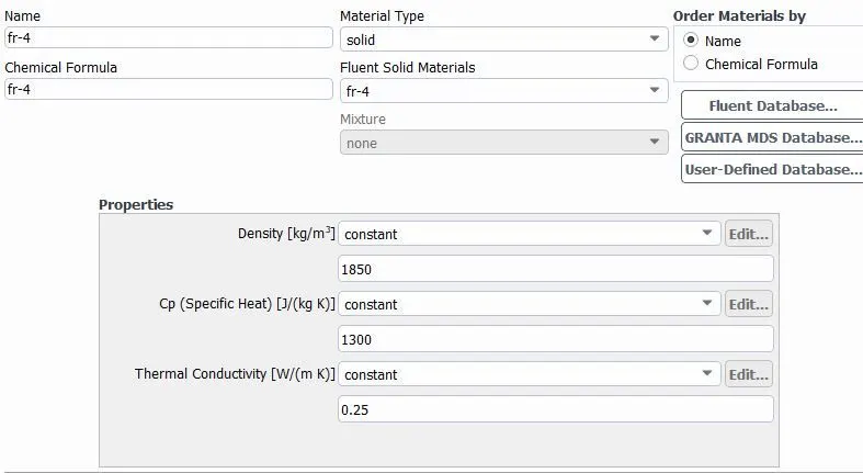
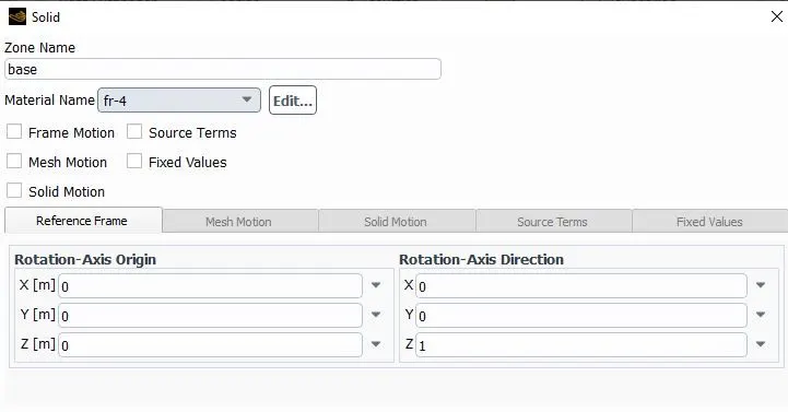
Base - FR4 (Glass rainforced epoxy laminate) is usewd for base of the graphic card.
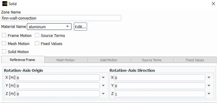
Now I have to assign the material accordinagly. (Cell zone condition)
For fin of the card
For base of the card
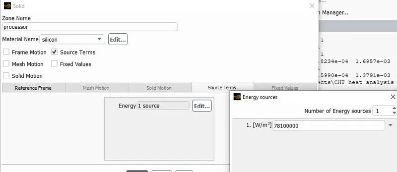
For processor of the card
Heat generated = power/volume of the processor
here power = 5W,
volume of the processor = 8 x 8 x 1 mm= 64 mm^3 = 64 x 10^-9 m^3
Heat generated = 5/(64 x 10^-9) = 7.81 x 10^7 W/m^3
Inlet velocity will be 2 m/s for boundary condition.
Inlet velocity = 2 m/s.
Now initialize the simulation by hybrid initialization.
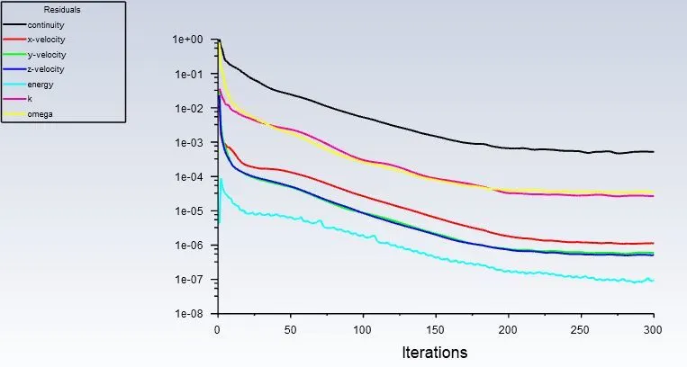
Simulate for 300 iterations.
Solution :-
Residuals :-
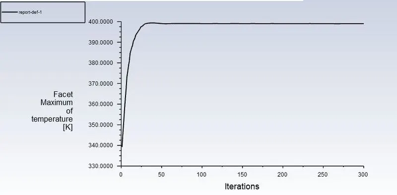
maximum temperature attained by the processor
Tmax = 399.18 K
Surface heat transfer coefficient of processor = 8.48 W/(m^2 K)
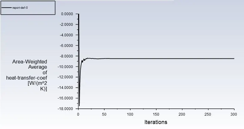
Quantities leaving the surface being measured will be taken as negative by Fluent, hence it is the sign convention of fluent due to which we are getting a negative value.
Solution :-
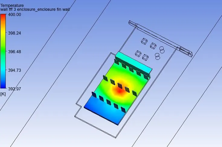
fin temperature distribution
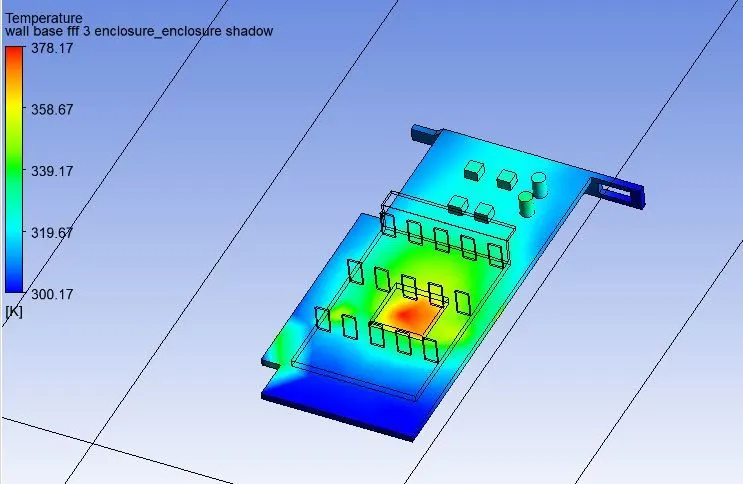
base temperature distribution
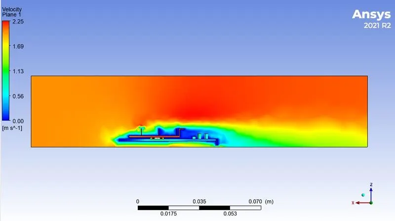
Velocity contour
Pressure contour
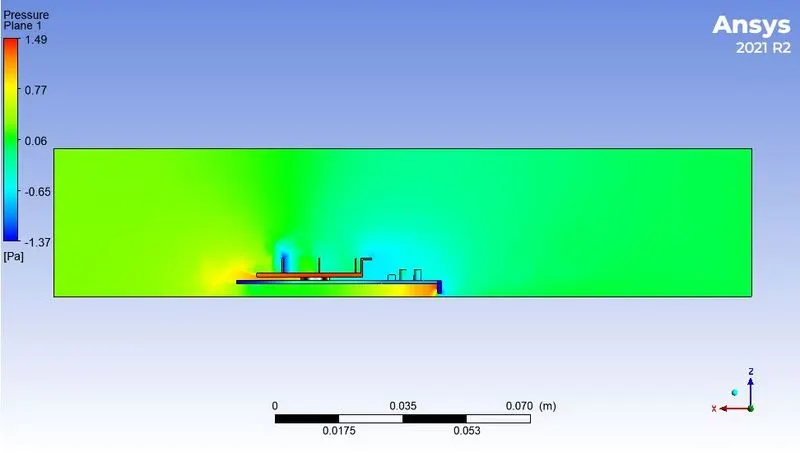
Temperature contour

velocity vector plot
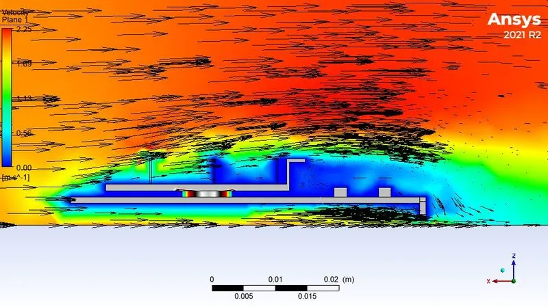
Here we can not see proper wake region formed behind the fin. Because we have done coarse meshing.
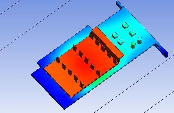
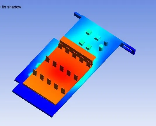
Global hotspot region
Meshing :- (refined case 1)
Apply the elements size 3 mm . Apply body sizing on processor = 0.5 mm, body sizing on Fin = 1 mm, body sizing on base = 2 mm Provide the named selection accoradigly.
Total number of elements = 164931
Setup :-
Setup will remain same as the base simulation.
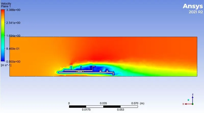
Inlet velocity will be 3 m/s for boundary condition.
Inlet velocity = 3 m/s.
Now initialize the simulation by hybrid initialization.
Simulate for 300 iterations.
Solution :-
Residuals :-
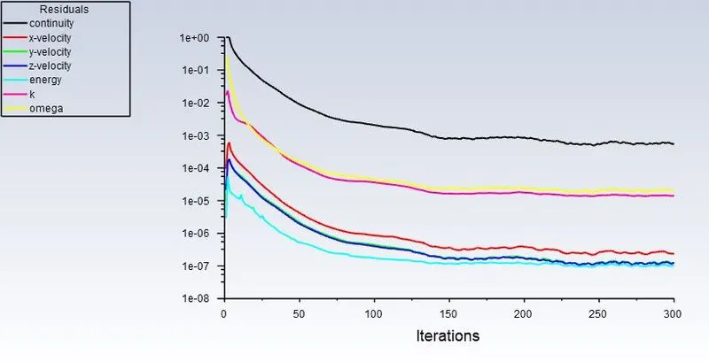
maximum temperature attained by the processor
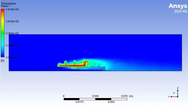
Tmax = 381.36 K
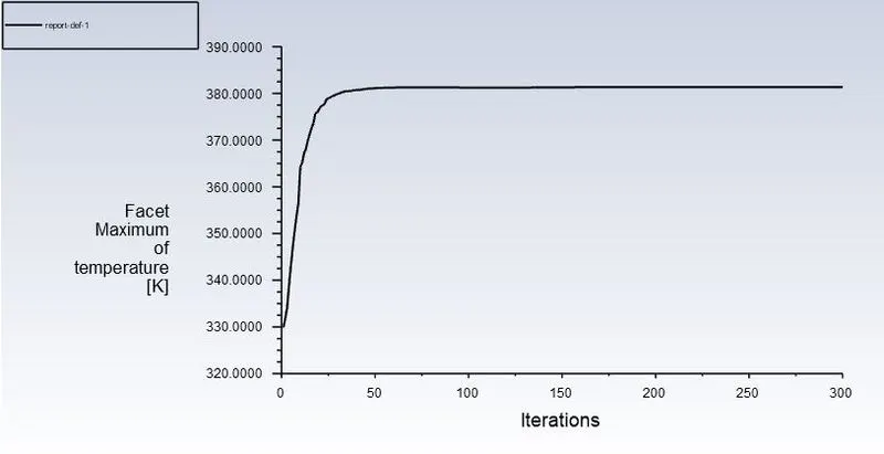
Surface heat transfer coefficient of processor = 11.92 W/(m^2 K)
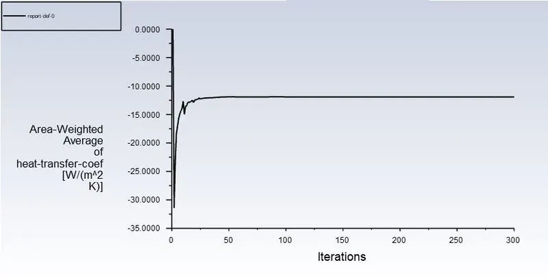
Quantities leaving the surface being measured will be taken as negative by Fluent, hence it is the sign convention of fluent due to which we are getting a negative value.
Solution :-
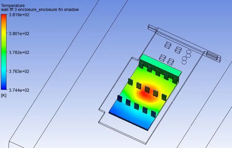
fin temperature distribution
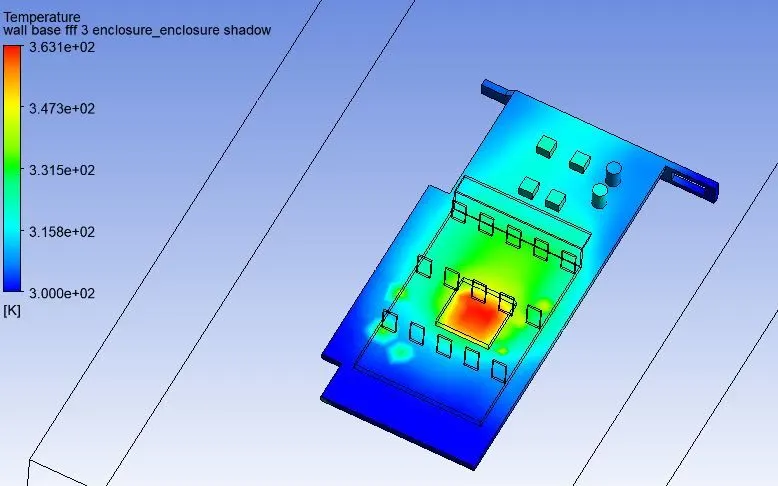
base temperature distribution
Velocity contour
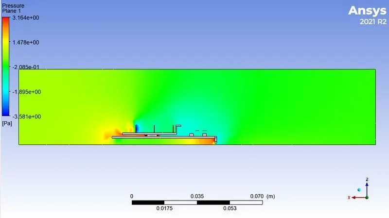
Pressure contour
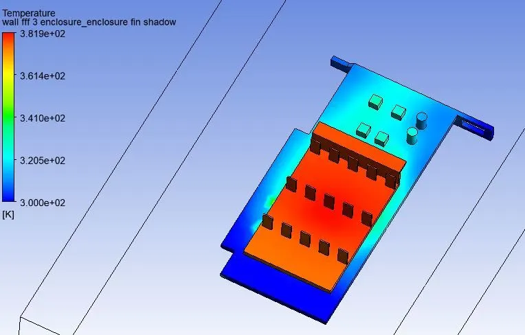
Temperature contour
velocity vector plot
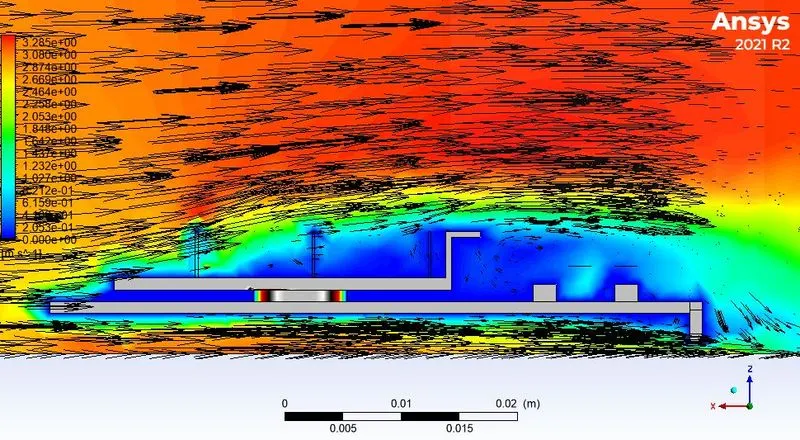
Here we can clearly see that the behind the fin there is wake region formed.
Global hotspot region
Meshing :- (refined case 2)
Apply the elements size 3 mm . Apply body sizing on processor = 0.5 mm, body sizing on Fin = 1 mm, body sizing on base = 2 mm Provide the named selection accoradigly.
Total number of elements = 164931
Mesh metric :-
Here we can see that most of the elements are having higher quality in the range of 75% - 95%
Setup :-
Setup will remain same as the base simulation.
Inlet velocity will be 4 m/s for boundary condition.
Inlet velocity = 4 m/s.
Now initialize the simulation by hybrid initialization.
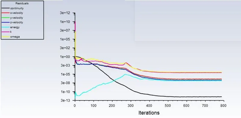
Simulate for 800 iterations.
Solution :-
Residuals :-
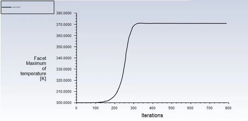
maximum temperature attained by the processor
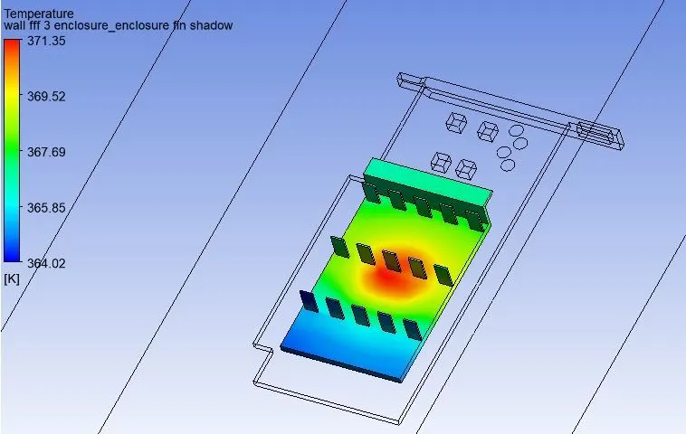
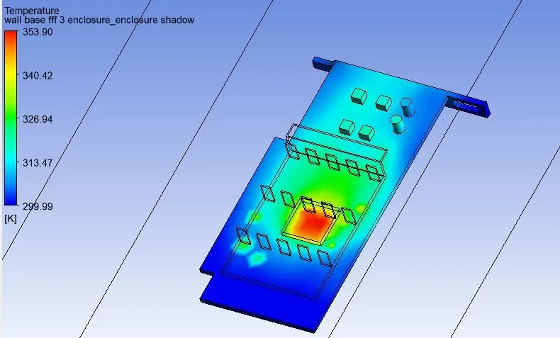
Tmax = 370.82 K
Surface heat transfer coefficient of processor =14.37 W/(m^2 K)
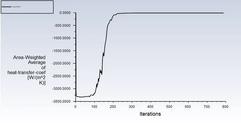
Quantities leaving the surface being measured will be taken as negative by Fluent, hence it is the sign convention of fluent due to which we are getting a negative value.
Solution :-
fin temperature distribution
base temperature distribution
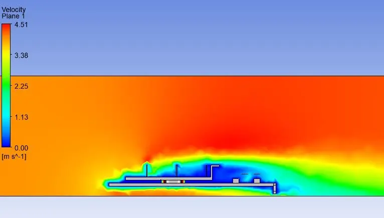
Velocity contour
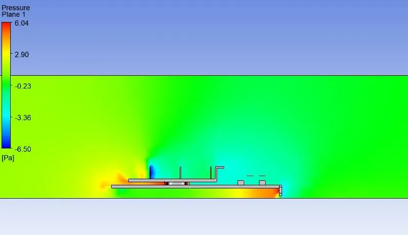
Pressure contour
Temperature contour
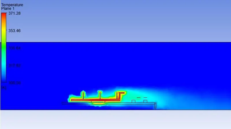
Velocity vector plot
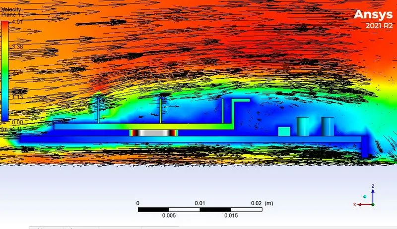
Here we can clearly see that the behind the fin there is wake region formed.
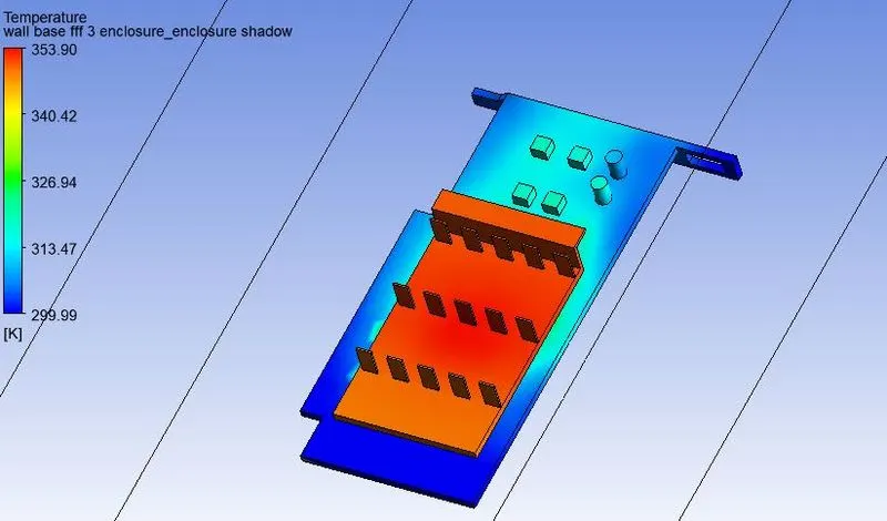
Global hotspot region
Meshing :- (refined case 3)
Apply the elements size 3 mm . Apply body sizing on processor = 0.5 mm, body sizing on Fin = 1 mm, body sizing on base = 2 mm Provide the named selection accoradigly.
Total number of elements = 164931
Mesh metric :-
Here we can see that most of the elements are having higher quality in the range of 75% - 95%
Setup :-
Setup will remain same as the base simulation.
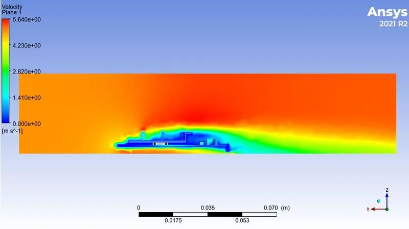
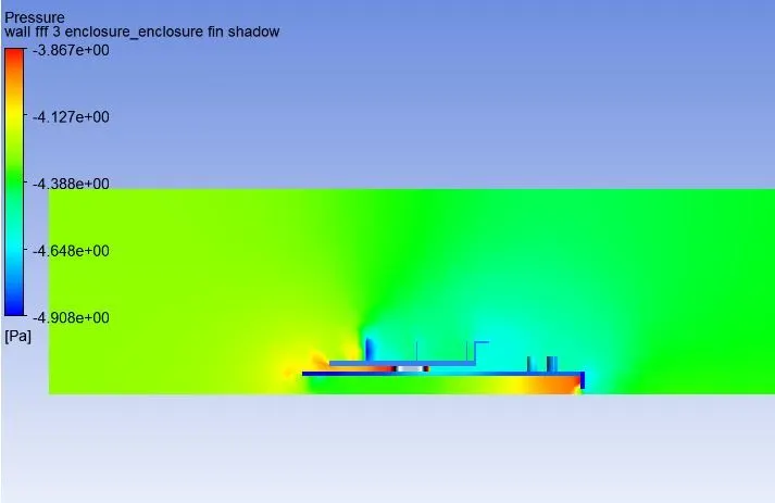
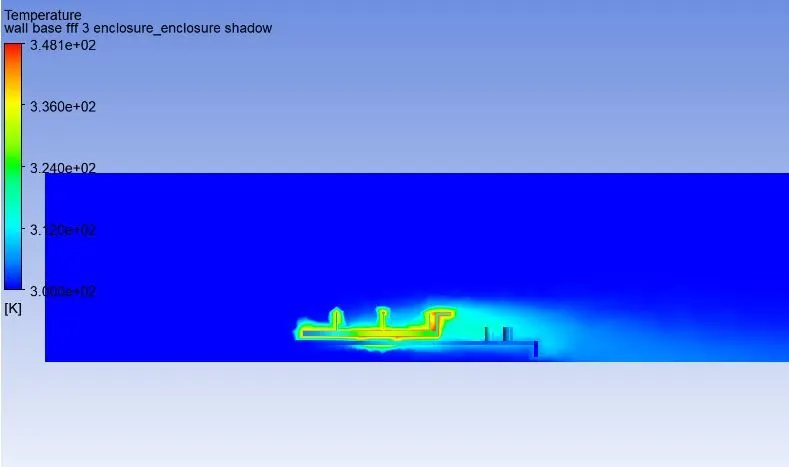
Inlet velocity will be 5 m/s for boundary condition.
Inlet velocity = 5 m/s.
Now initialize the simulation by hybrid initialization.
Simulate for 1000 iterations.
Solution :-
Residuals :-
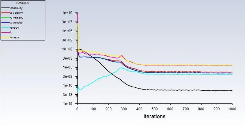
maximum temperature attained by the processor
Tmax = 364.44 K
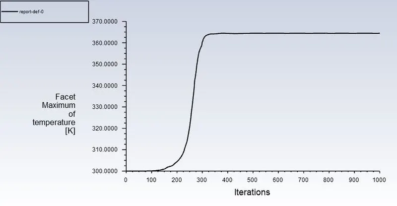
Surface heat transfer coefficient of processor = 16.71 W/(m^2 K)
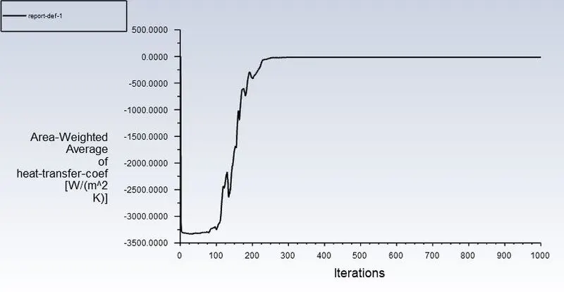
Quantities leaving the surface being measured will be taken as negative by Fluent, hence it is the sign convention of fluent due to which we are getting a negative value.
Solution :-
fin temperature distribution
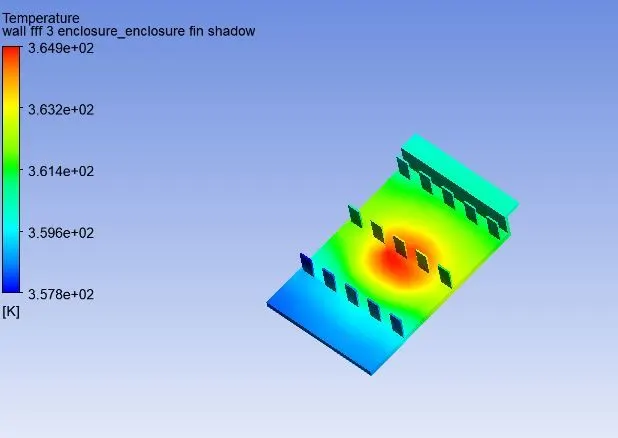
base temperature distribution
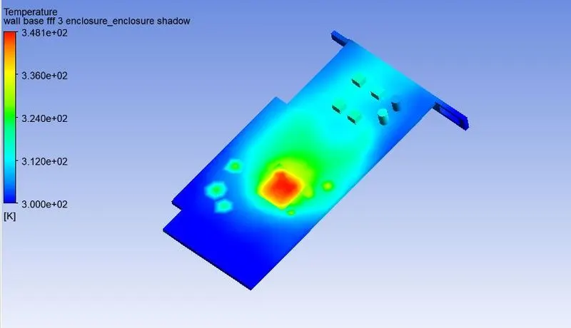
Velocity contour
Pressure contour
Temperature contour
Velocity vector plot
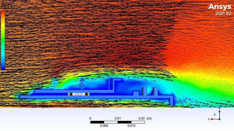
Here we can clearly see that the behind the fin there is wake region formed.
Global hotspot region
CONCLUSION :-
As the number of elements increases the accurate results of temperature distribution is obtained
From the above table, it is fairly notable that, the max temperature of components of graphics cards decreases
with an increase in inlet velocity.
Hence it can be inferred that a higher inlet velocity results in better cooling and lower the maximum temperature
thus keeping the components safe from damage.
| Velocities | Max temperature attained by processor (K) | Surface heat transfer coefficient of processor [W/(m^2 K)] |
| 2 m/s (coarse mesh) | 399.18 | 8.48 |
| 3m/s (refined mesh) | 381.36 | 11.92 |
| 4 m/s (refined mesh) | 370.82 | 14.37 |
| 5 m/s (refined mesh) | 364.44 | 16.71 |