Week 6 - CHT Analysis on a Graphics card
Objective:-
Perform a steady-state conjugate heat transfer analysis on a model of a graphics card. You can use appropriate materials of your choice for the simulation. Make sure to properly define the correct solid and fluid zones. Refer the video for further clarification and the model is provided below the video.
Run the simulation for best possible mesh with combination of coarse and refined mesh in different regions. Explain the reason for choosing the particular mesh settings.
- Run the simulation by varying the velocity from 1m/sec to 5m/sec for at least 3 velocities and discuss the results.
- Find out the maximum temperature and heat transfer coefficient attained by the processor.
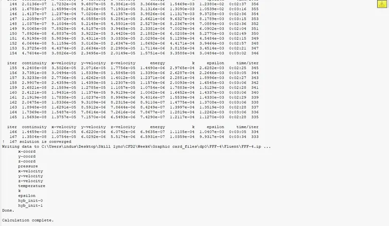
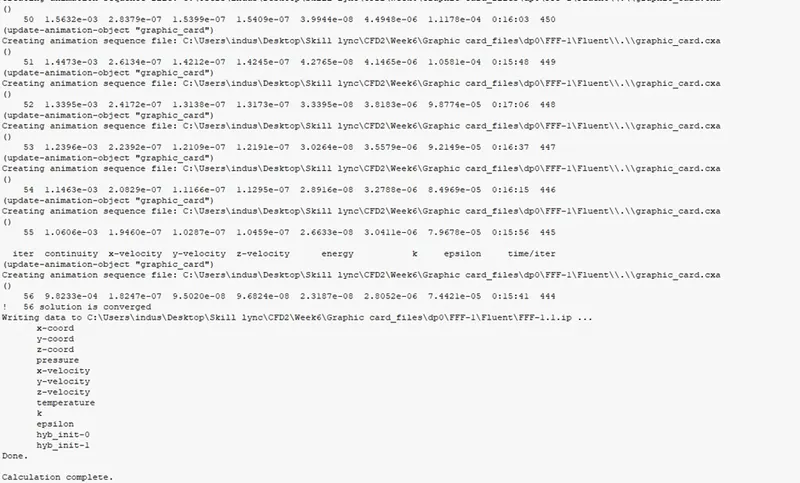
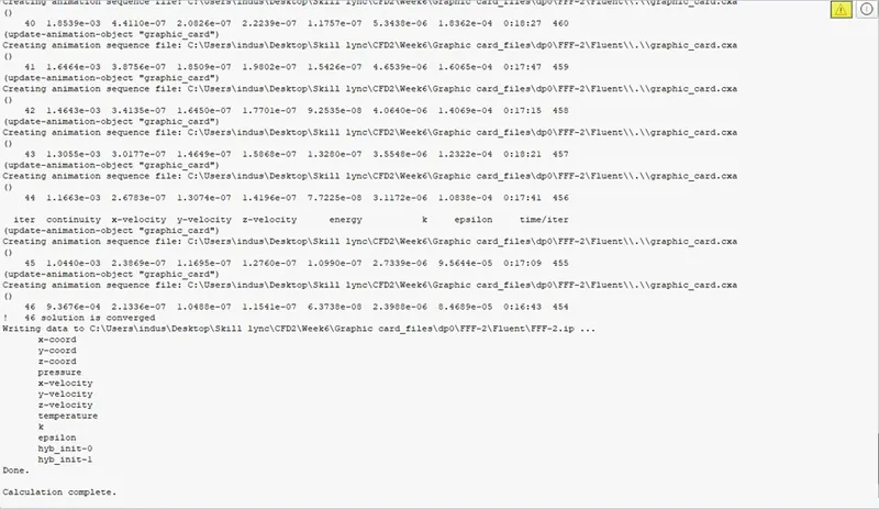
- Prove that the simulation has achieved convergence with appropriate images and plots.
- Identify potential hotspots on the model.
Procedure:-
Geometry
Loading the Geometry in SpaceClaim
Base
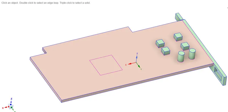
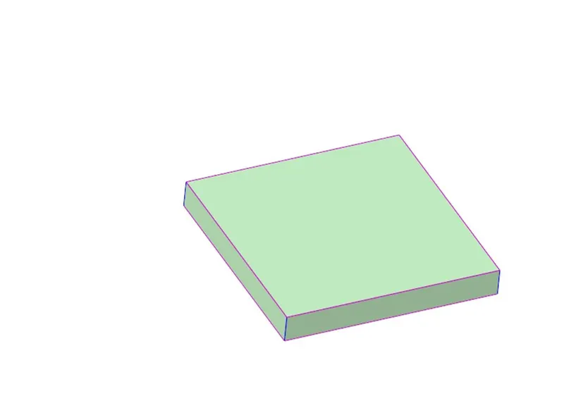
Processor
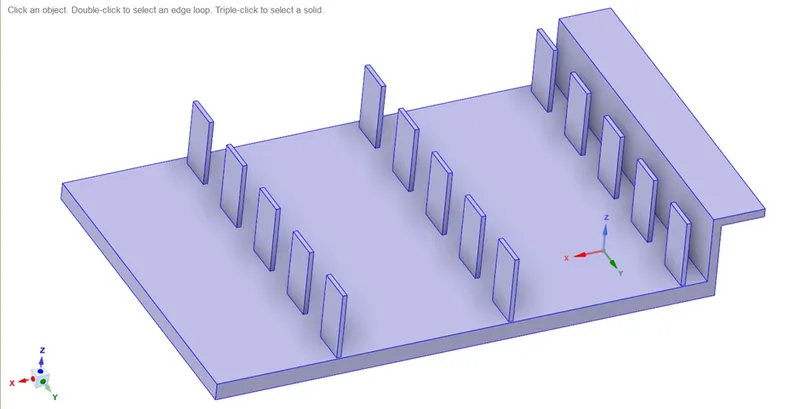
Fins
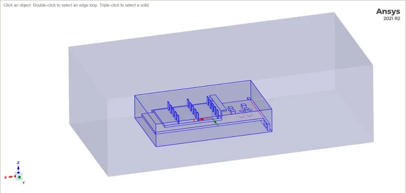
Model enclosed in two enclosure
Topology is set to share so that the data can be shared between different components of the graphic card
Meshing
Baseline mesh
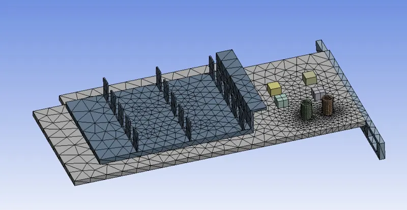
The first simulation will be carried out on a baseline mesh with an element size of 3mm
Fine mesh
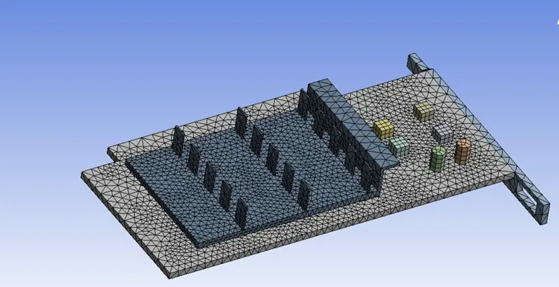
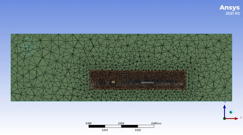
The next simulation would be done by refining the mesh. There will be two enclosures. The first enclosure will be meshed with an element size of 5mm and the second enclosure with an element size of 0.8mm using the sizing method
Named sections
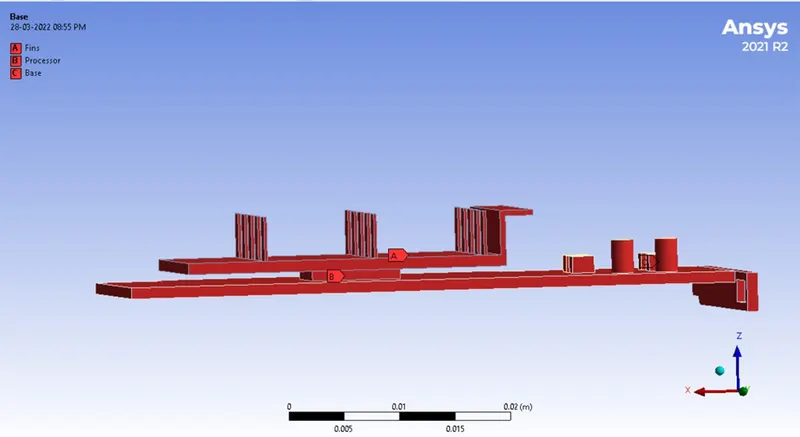
Setup of the model
- Solver – Steady
- Type – Pressure based
- Turbulence model – k-epsilon with Realizable Enhanced wall treatment
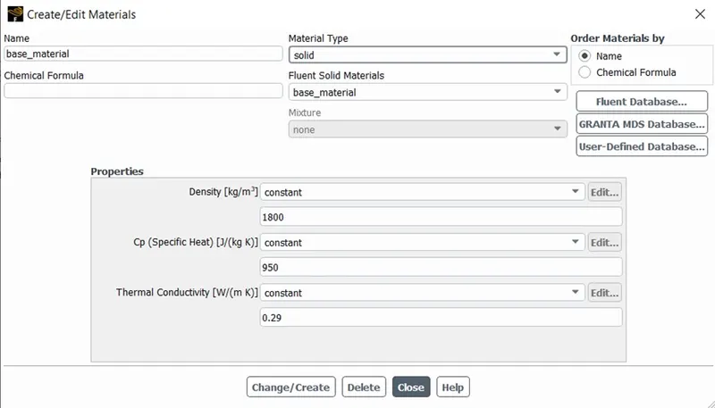
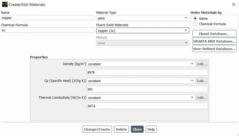
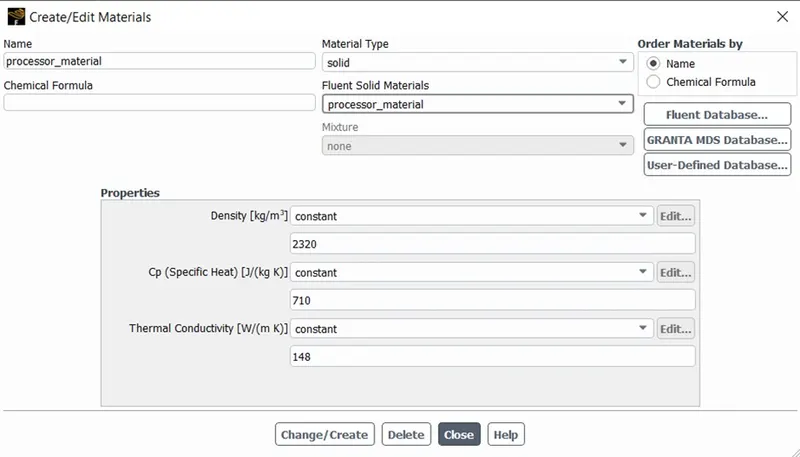
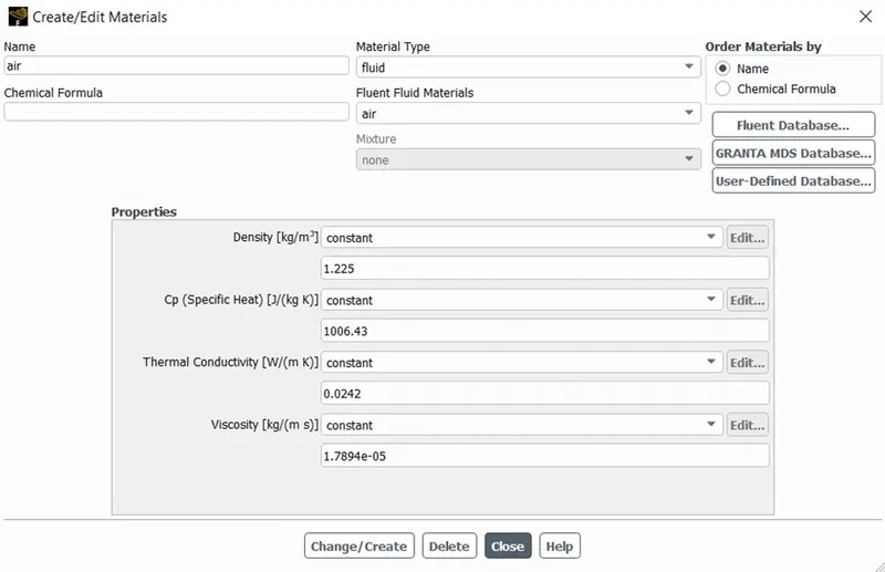
- Materials – Different materials are used for different parts and some of them are custom created
|
Parts |
Materials |
|
Base |
Base_material |
|
Fins |
Copper |
|
Processor |
Processor_material |
|
Enclosure |
Air |
- Base material
- Copper
- Processor material
- Air
Boundary conditions
- Inlet
Type: Velocity inlet
Velocity: 5m/s
Temperature: 300K
- Outlet
Type: Pressure Outlet
Pressure: 0 Pa
Temperature: 300K
Cell zone conditions
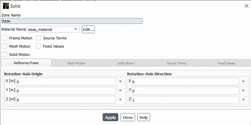
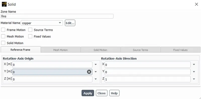
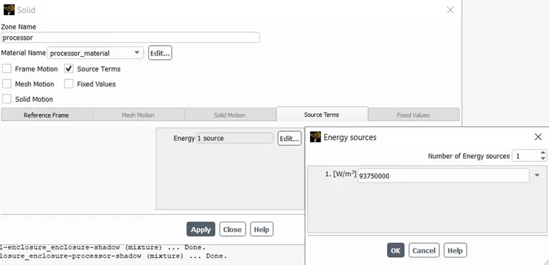
The processor is the only source of heat. The heat generated by the processor is calculated as
Graphic card power = 6W
Volume of processor = 8 x 8 x 1 = `64mm^3` = `64*10^-9 m`
Heat generated = `P/V` = `6/(64*10^-9)` = `93750000 W/m^3`
The solution is then initialized with Hybrid Initialization and is set to run for 500 iterations
Results
Baseline mesh
Velocity 5m/s
Solution convergence
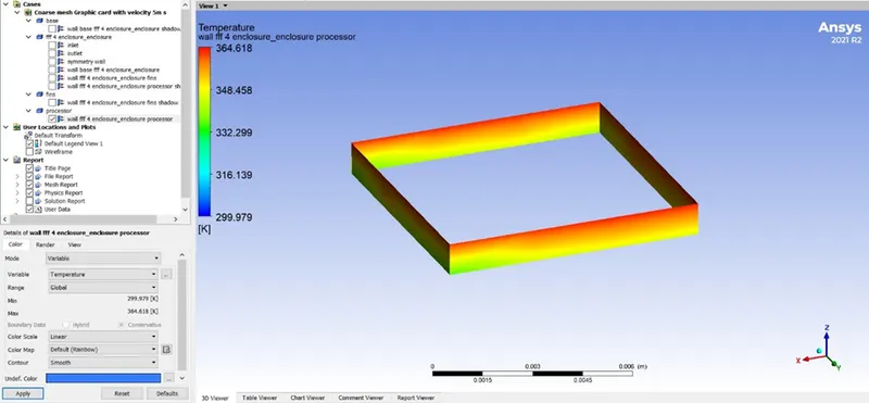
Maximum Temperature attained by the processor
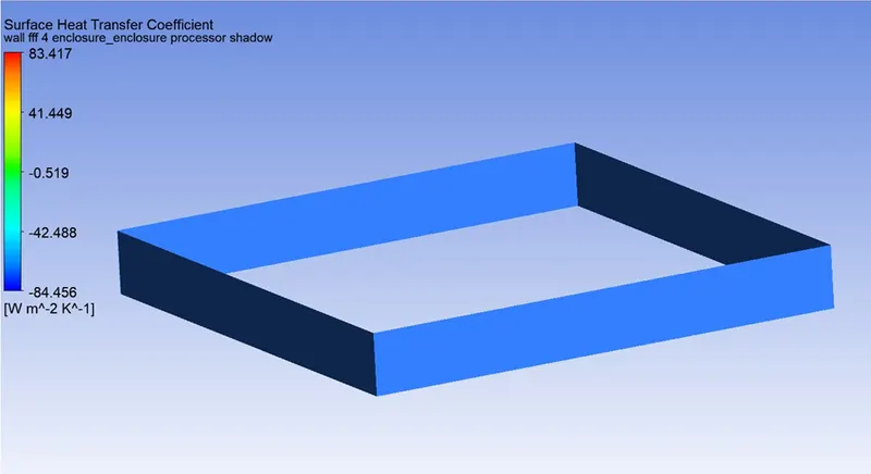
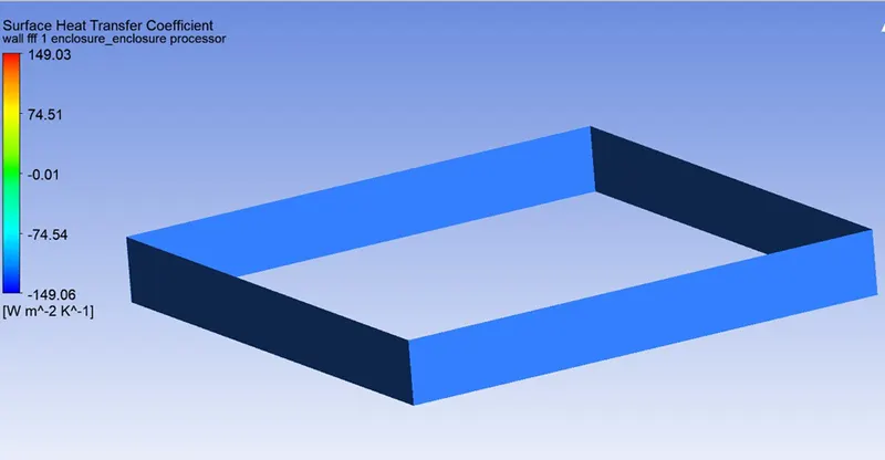
Surface Heat Transfer Coefficient of the processor
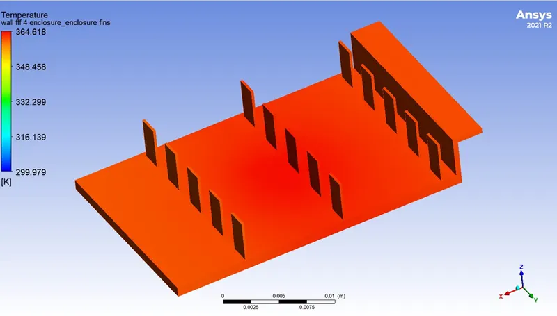
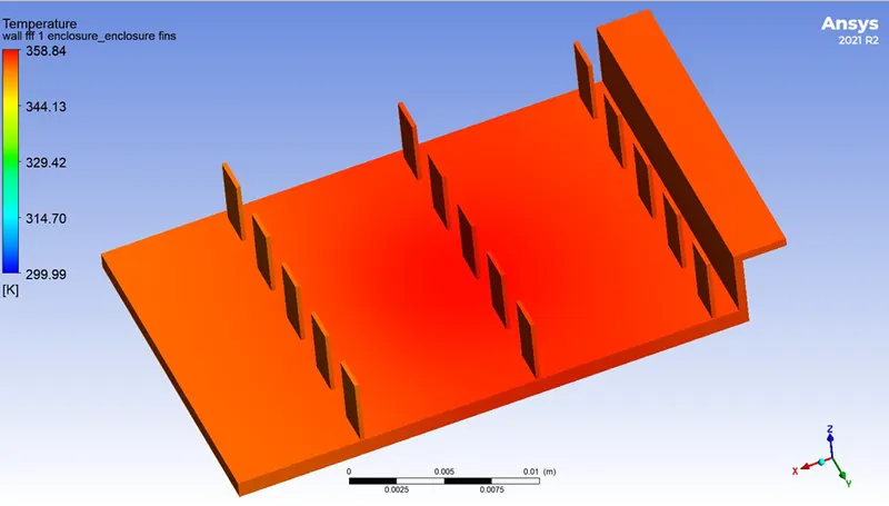
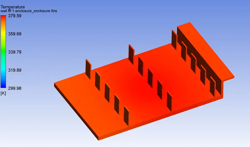
Maximum Temperature conducted by fins
Fine Mesh
Velocity 5m/s
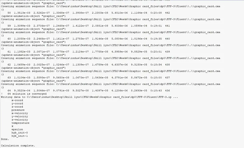
Solution convergence
Maximum Temperature attained by the processor
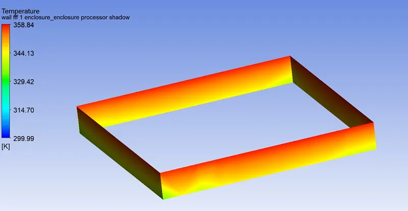
Surface Heat Transfer Coefficient of the processor
Maximum Temperature conducted by fins
Velocity 3m/s
Solution convergence
Maximum Temperature attained by the processor
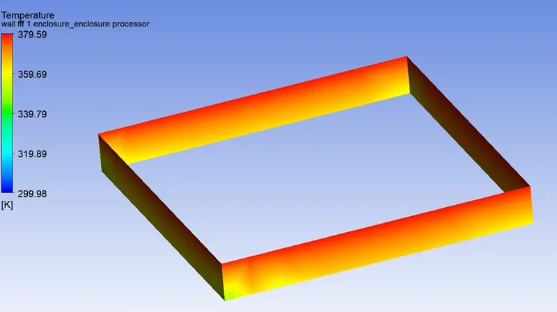
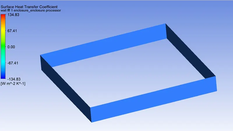
Surface Heat Transfer Coefficient of the processor
Maximum Temperature conducted by fins
Velocity 1m/s
Solution convergence
Maximum Temperature attained by the processor
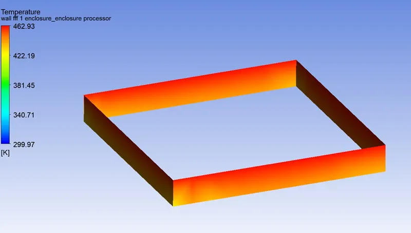
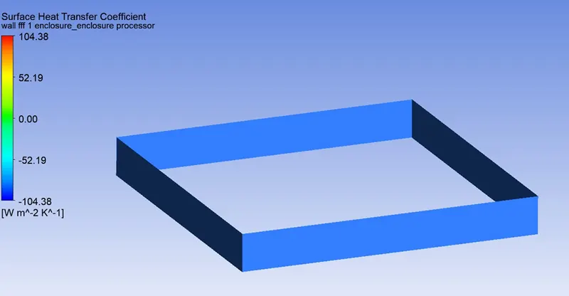
Surface Heat Transfer Coefficient of the processor
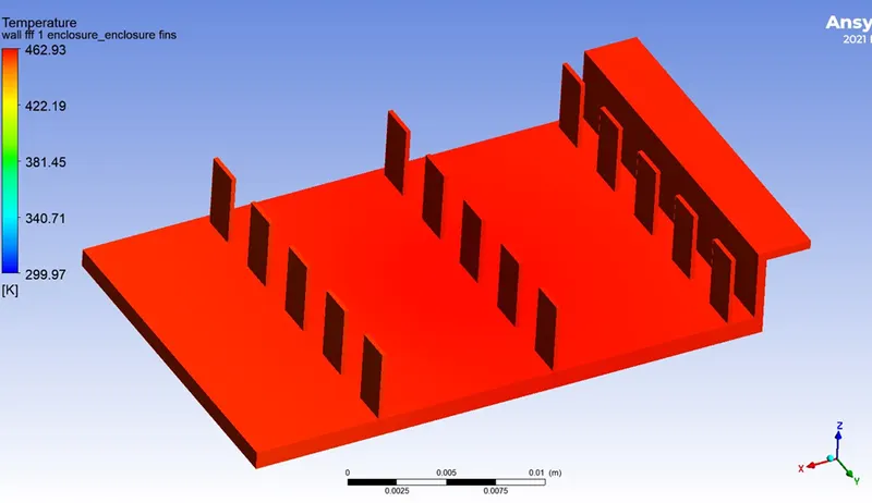
Maximum Temperature conducted by fins
Potential Hotspot region on Fins as well as on Base of the processor
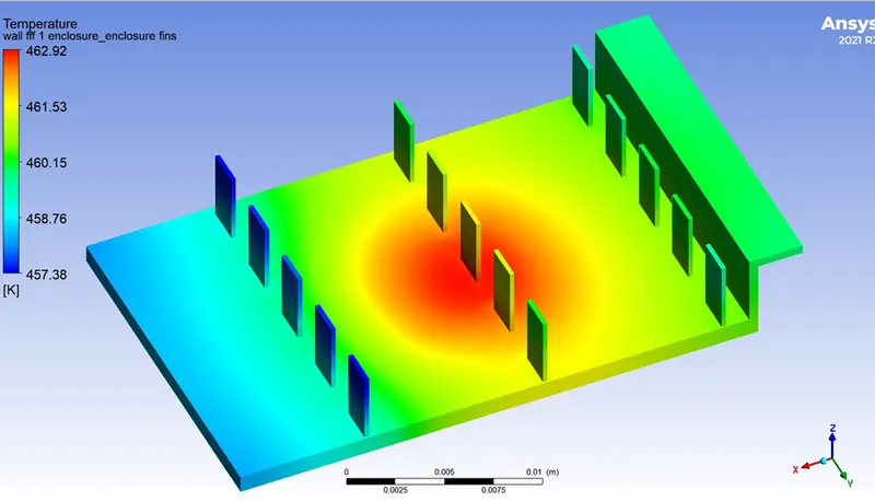
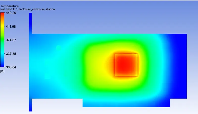
The Potential hotspots on fins and on the base will be same for all the cases
|
Parameters |
1m/s |
3 m/s |
5 m/s |
|
Maximum Temperature (K) |
462.93 |
379.59 |
358.84 |
|
Surface Heat Transfer Coefficient (W/m^2K) |
104.38 |
134.83 |
149.06 |
|
Solution convergence |
46 |
56 |
167 |
Conclusion:-
As seen above it is concluded that the more finer the mesh, the better is the result.
As the velocity increases the Surface Heat Transfer Coefficient also increases and the Temperature of the Processor decreases