Week 6 - CHT Analysis on a Graphics card
CHT analysis on a Graphics card
Let us discuss about the Conjugate Heat Transfer
CHT analysis type allows the simulation of heat transfer bewteen the interface of solid and fluid regions by exchnging the thermal energy at the interface between solid and fluid. CHT is a combination of heat transfer in solids and fluids. In solids, conduction dominates and in fluids, convection dominates. Heat is transferred via interface and transported via conduction within solid and additionally via convection in fluid domain.
Due to fluid motion, below are the contributions to heat transfer,
- Convective contribution: Depending upon, fluid velocity, its properties , there will be convetion and conduction heat transfer.
- Viscous effects: When flow occurs, viscosity of the fluid creates heat and this heat must be taken into account for high velocity flows.
- Density contribution: If in the flow , density is dependent upon temperature, the different regions will have different temperatures so densities. Hence, there will be compression of air which will produce heat.
The applications are electronic enclosures, effective coolers, heat exchangers, heaters.
Problem : We have a model similar to Graphics card containing processor, fins, base, enclosure of fluid, capacitors. We need to simulate conjugate heat transfer on the card as card consists of solid parts and fluid region as well. We have to find out the maximum temperature and heat trasnhfetr coefficient on the processor of the graphics card. Processor is a major source of heat generation. Base is used for connection and fins are used for dissipating heat by convection to fluid domain. Fins are placed on the heat generator i.e. processor such a way that most of the heat generated can be conducted to the fins and as the air passes through the fins, there is convection that helps to release heat into air. For this better dissipation, fins material is of high thermal conductivity like copper. At the same time, we do not want the heat to be transported to the other components of the base , so the base material is generally wood or silica. So, according to this we will use below materials,
Component Material
Fins Copper
Processor Aluminium
Base Silica
Enclosure Air
We have also considered enclosure so that we will understand external flow and how much heat its taking from fins.
Steps to simulate CHT analysis are as below,
step 1: Load the geometry in SpaceClaim and enable Share option from Workbench and make share topology for each component.
step 2: Meshing the geometry with required sizing.
step 3: Loading the mesh into Fluent setup and setting up physics.
step 4: Setting up the solver settings and calculate the solution.
step 5: Postprocess the results and get various contours, plots.
Simulation 1 (Baseline mesh)
STEP 1
Import the geomerty into SpaceClaim.
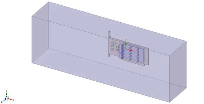
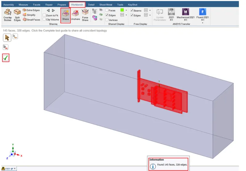
Now, go to Share option in Workbench and select it to share all the faces and edges. It will share the entire topology. It will turn all faces. edges red also we get message like number of faces shared. Now, click on green tick to share and shared topology will be completed.
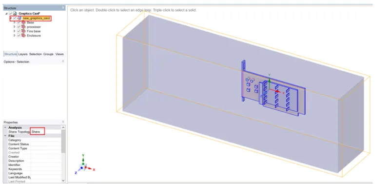
We can now see that edges of shared boundaries are turned blue and in the tree when we look for the properties of the graphic card it shows share for shared topology. This means that mesh is conformal and can be used for further analysis.
STEP 2
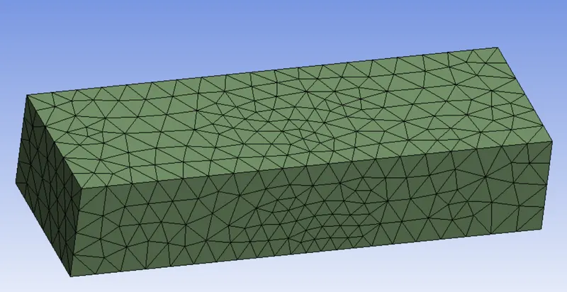
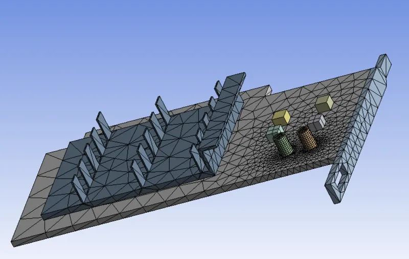
Moving to Meshing part, we are creating baseline mesh first and look for the quality of it.
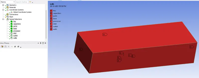
Let us create named selection for all the components as below,
Mesh matrix
Now, let us proceed to set up physics as below,
Fluent setup
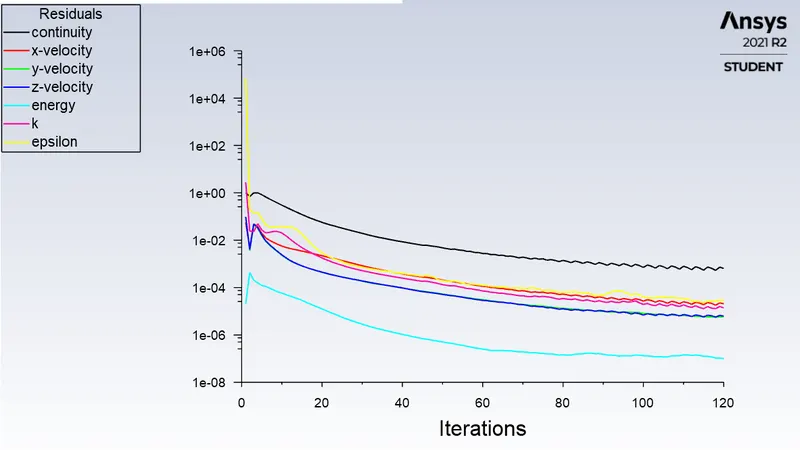
We will use pressure-based solver and steady state simulation.
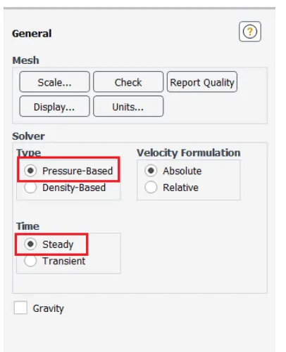
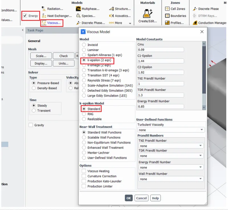
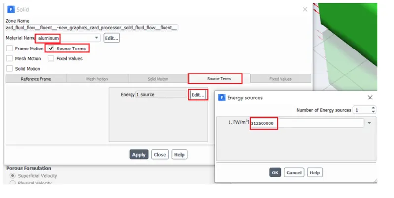
As we want to know maximum the temperature and heat transfer coefficient of processor, energy equation must be on in that case.
We are selecting viscous model as k-Epsilon standard.
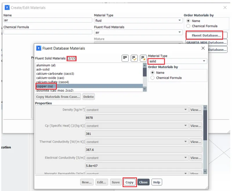
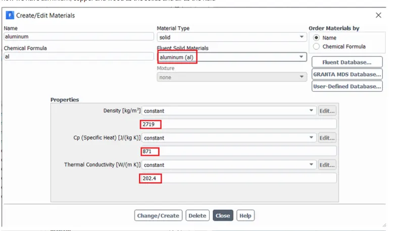
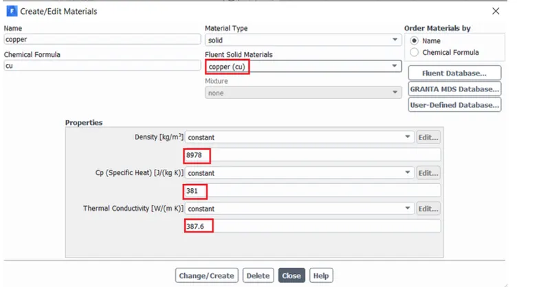
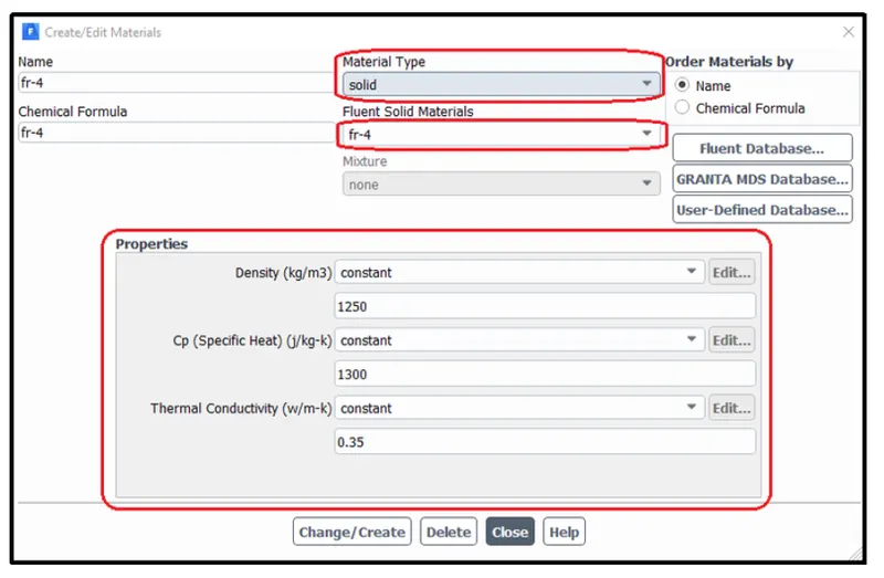
We will be creating materials as below,
Processor - Copper
Fins- Aluminium
Base- FR4
Capacitors, ports- FR4
enclosure- Air
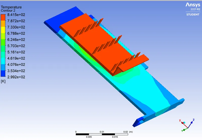
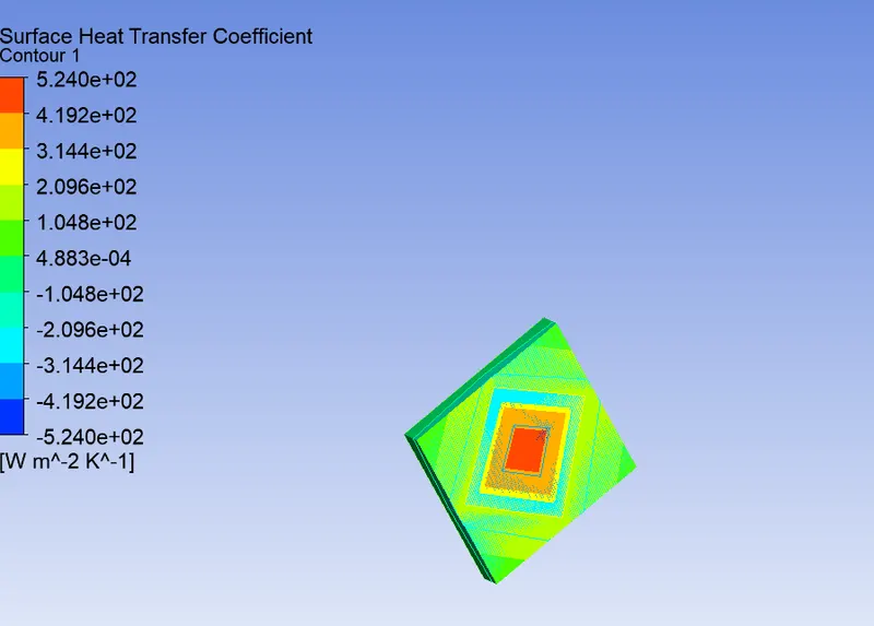
Now, Let us refine the mesh as below,
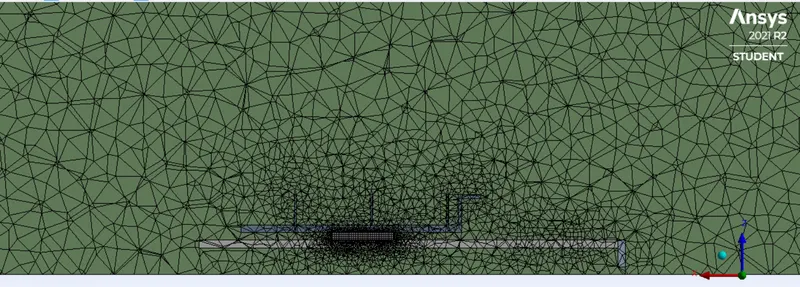
We use the same geometry as we used and we refine the main three sections processor, fins and enclosure as in this case, we are more interested in maximum temperature in processor, heat conduction through fins and heat convection via fins to enclosure air. Hence, we will refine in these areas mainly.
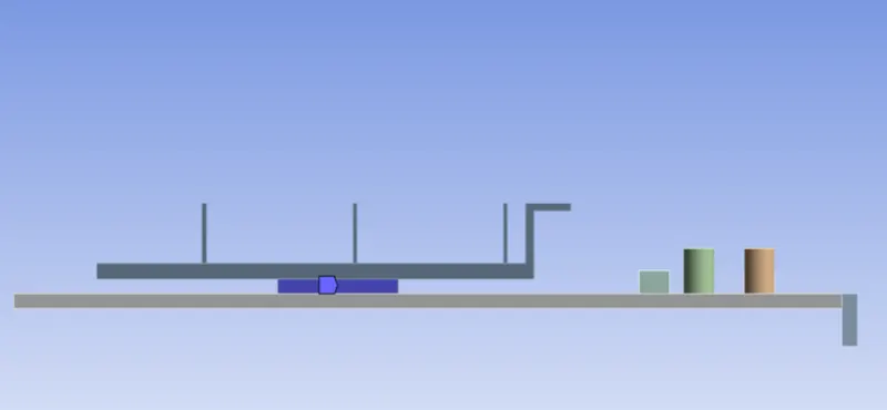
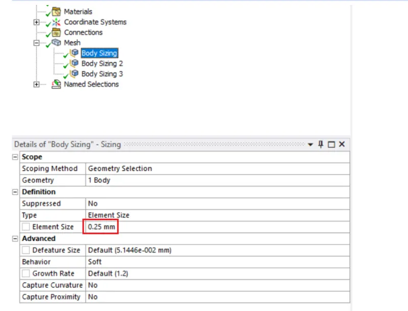
Next, we add body sizing in fins as 1mm element size.
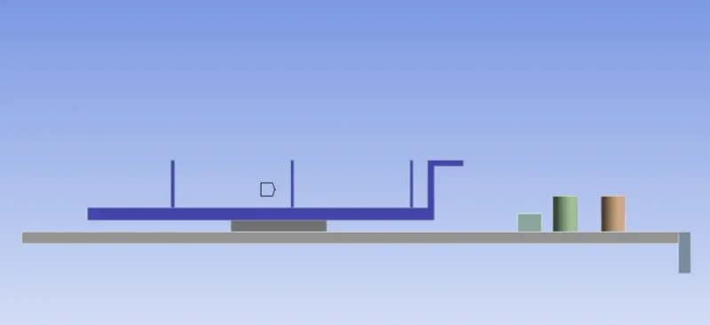
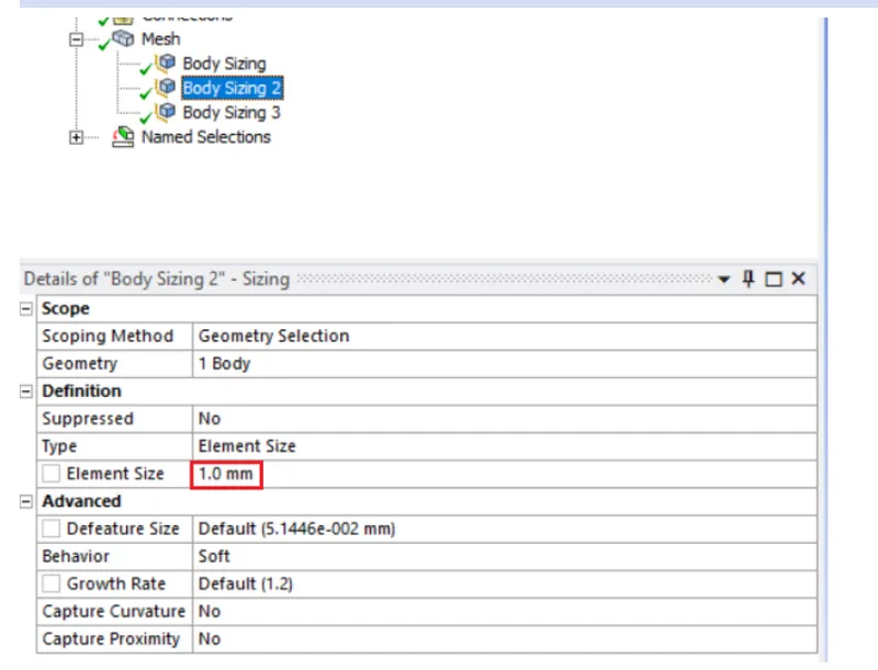
Next, add body sizing on enclosure as it is also important , beacuse heat is going to be dissipated here via fins.
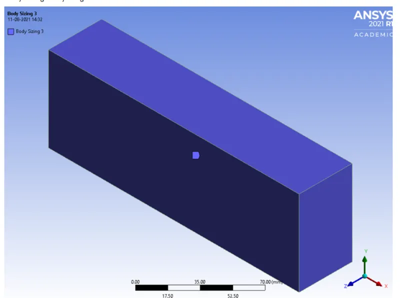
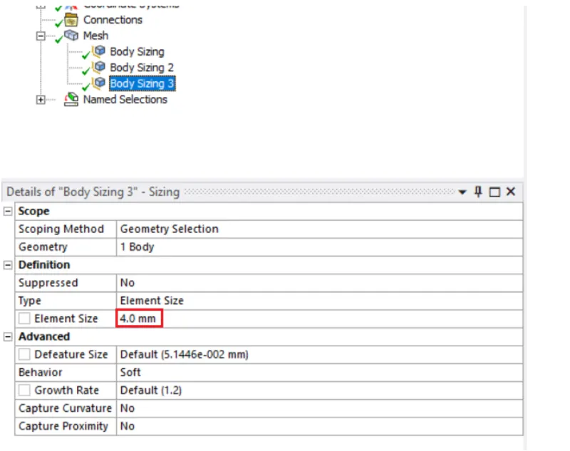
Overall meshing at section plane will look like,
Mesh statistics

Mesh Quality
a) Element quality
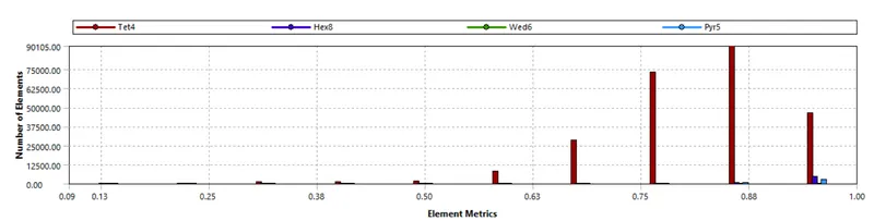
b) Skewness
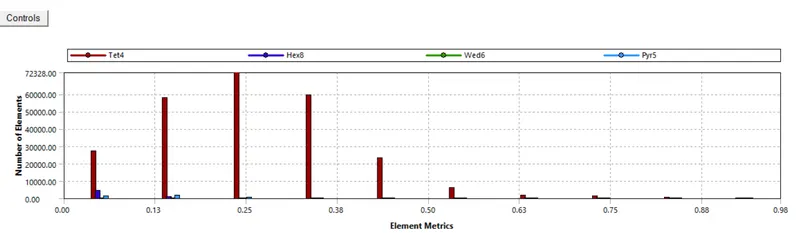
c) Orthogonal Quality
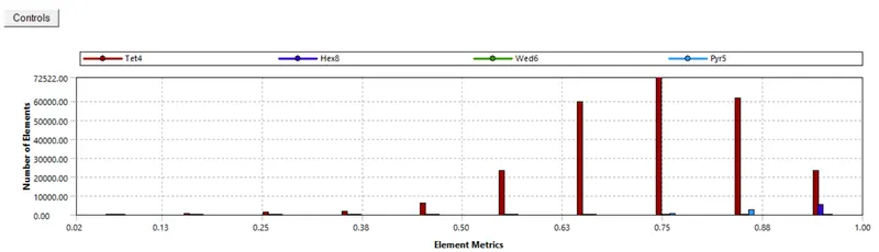
Mesh quality is better than basleine mesh.
Set up: It remians the same except the inlet velocity. Now, let us put v = 3m/s.
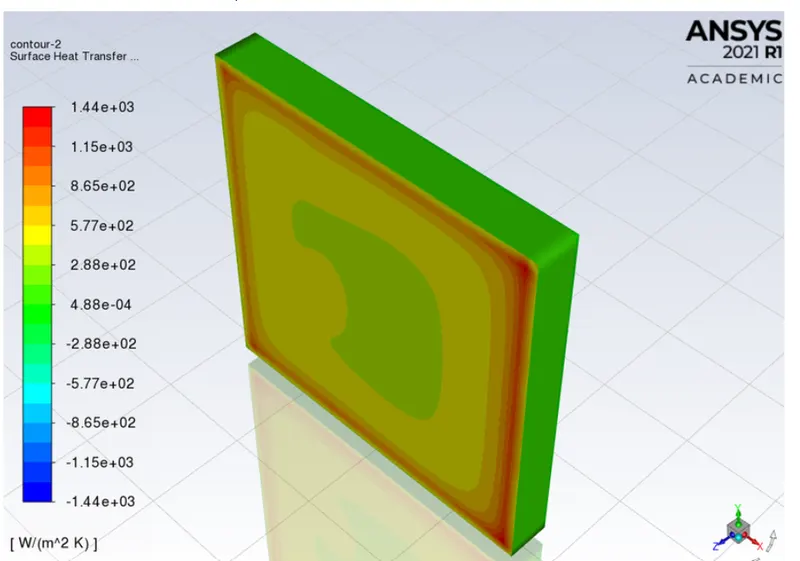
Results:
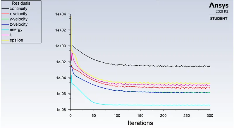
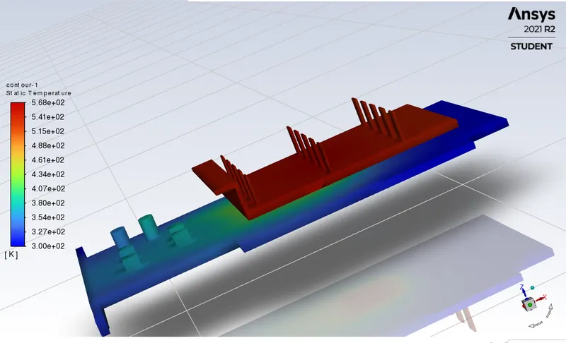
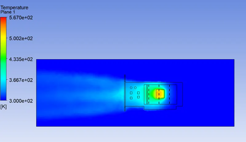
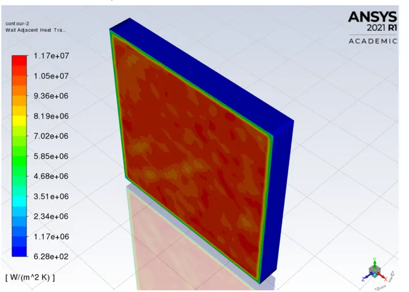
Mesh refinement 2
In this case, we refine the mesh more like below,
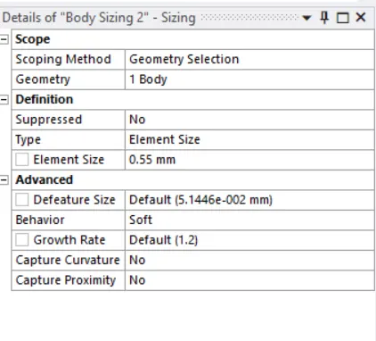
We give body sizing to enclosure as below,
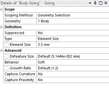
We give body sizing to fins as below,
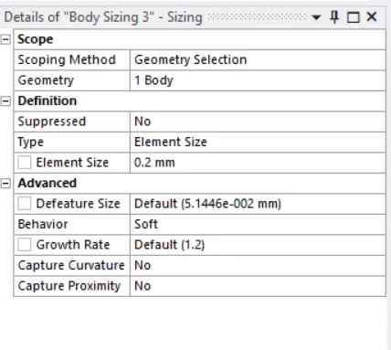
Body sizing to processor ,
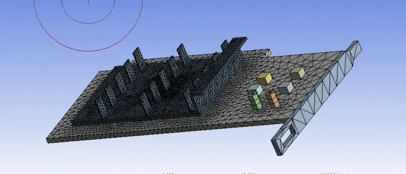
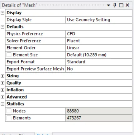
Total element count is 473267.
Mesh Quality:
1) Elemental quality
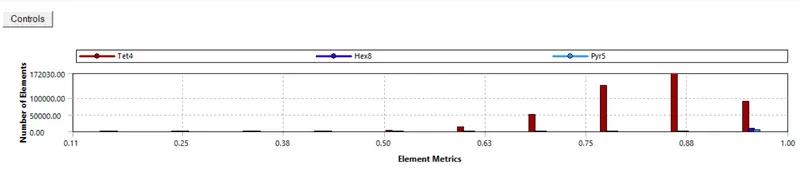
2) Skewness
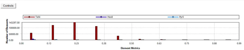
3) Orthogonal quality
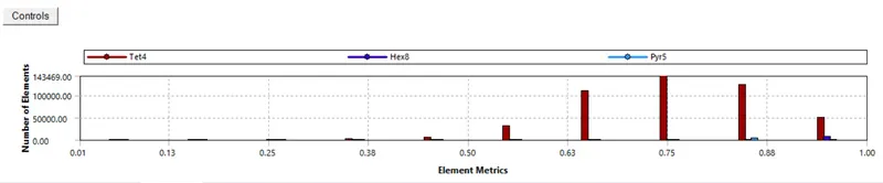
Setup remains the same as before except the velocity = 5m/s.
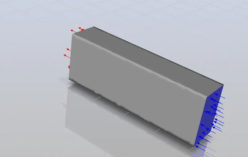
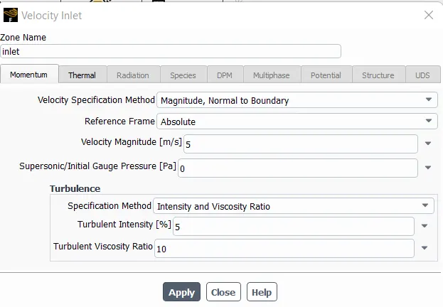
Results:
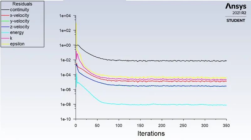
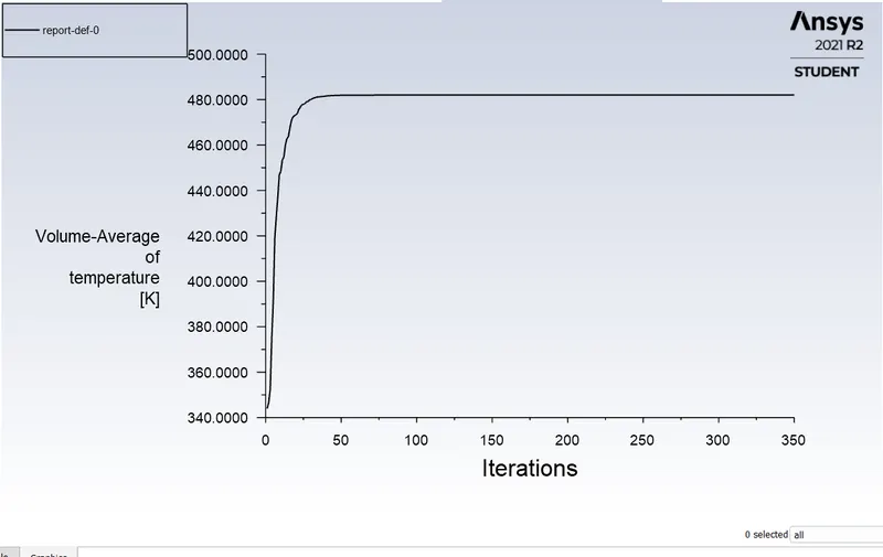
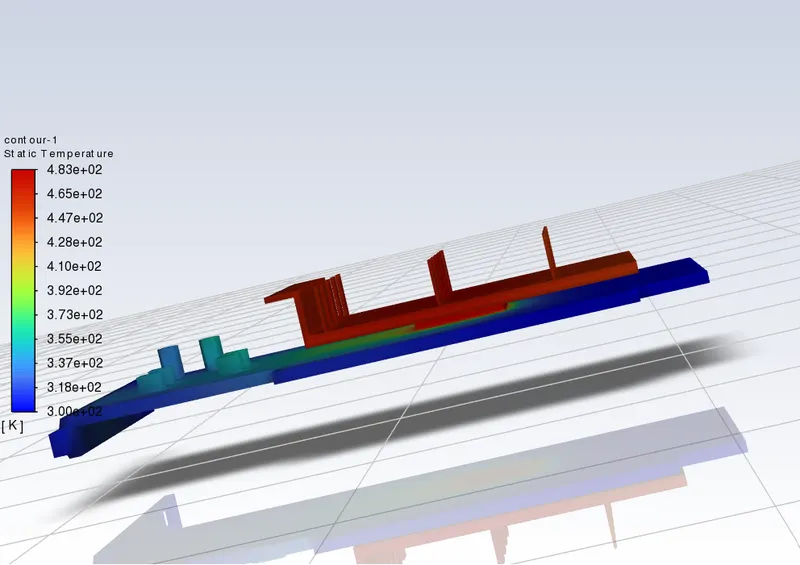
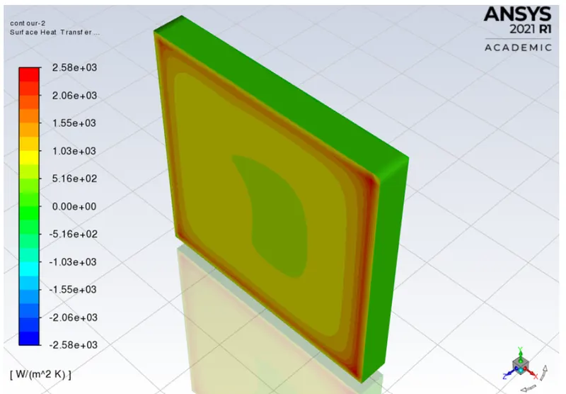
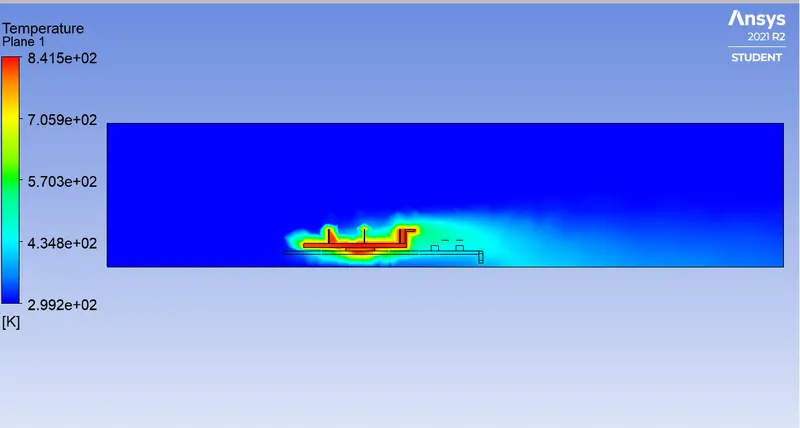
Flow velocity Volume averaged temperature for the processor surface heat transfer coeffcient (W/m^2-K)
1 m/s 841 K 524
3 m/s 568 K 1440
5 m/s 483 K 2580
Conclusion:
1. With increase in the velocity, the maximum temperature reduces.
2. With increasing the flow velocity, the surface heat transfer coefficient increases.
3. We should implement high velocity in order to keep the processor cool.