Week-6 Challenge: EV Drivetrain
Which types of power converter circuits are employed in electric and hybrid electric vehicle?
Power electronics is the application of solid state converters to the control and conversion of electric power.
The first high power electronic devices were mercury arc valves. In modern systems, the conversion is performed with semiconductor switching devices such as diodes, thyristors, and power transisitors such as the power MOSFET and IGBT. In contrast to electronic systems concerned with transmission and processing of signals and data, in power electronics substantial amounts of electrical energy are processed.
1. Power converter circuits :
This technology deals with processing and controlling the flow of electrical energy in order to supply voltages and currents in a form that is optimally suited for the instruments.
As shown in the above block diagram, it consists of an electrical energy source, a power electronic circuit, a control circuit and an electric load. This convertor changes one form of electrical energy to other forms of electrical energy. The power electronic circuit performs both the power part and the control part. The power part transfers the energy from source to load and it consists of power electronic switches, transformers, electric choke, capacitors, fuses and sometimes resistors. The control circuit regulates the elements in the power part of the converter. This block is built with a complex low power electronic that consists of either digital or analog circuit assembly.
Depending upon the functions performed, the following are the 4 different classifications
a) AC to DC converter which is called "Rectifier" - It converts AC into Unipolar DC current.
b) DC to AC converter which is called "Inverter" - It converts DC into AC of desired voltage and frequency.
c) DC to DC converter which is called "Chopper" - It converts High voltage DC to low voltage DC (Step down) or Low voltage DC to High voltage DC (Step up)
d) AC to AC converter which is called "Cycloconverter" - It converts the AC of the desired frequency and desired voltage magnitude from the AC supply.
Except for the AC to AC converter the other 3 are predominantly used in both the HEV and EV.
AC to DC converter (Rectifier) this used for charging the traction battery. Because the source of current is AC and the voltage stored in the traction Battery is DC.
The DC current from the Battery is then transmitted to 2 different converters, DC-AC converter (Inverter) and DC-DC converter (Chopper).
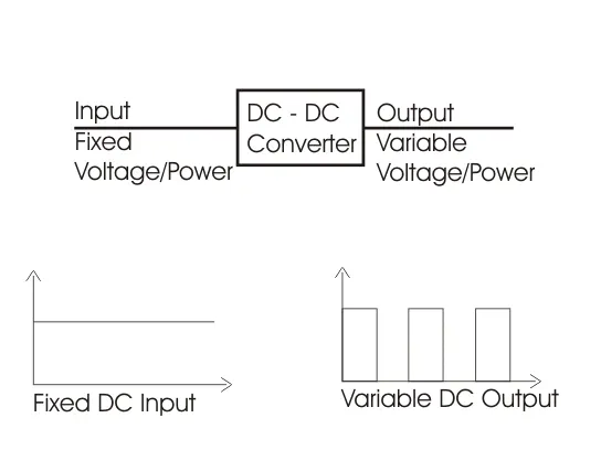
Chopper is a static power electronics device that converts fixed DC voltage/power to variable DC voltage or power. It is nothing but a high-speed switch that connects and disconnects the load from the source at a high rate to get variable or chopped voltage at the output.
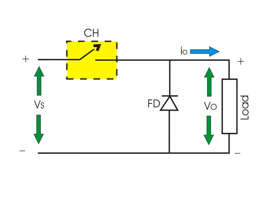
1) Step down Chopper :
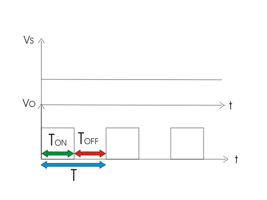
Step down chopper as Buck converted is used to reduce the i/p voltage level at the output side. Circuit diagram of a step down chopper is shown in the adjacent figure
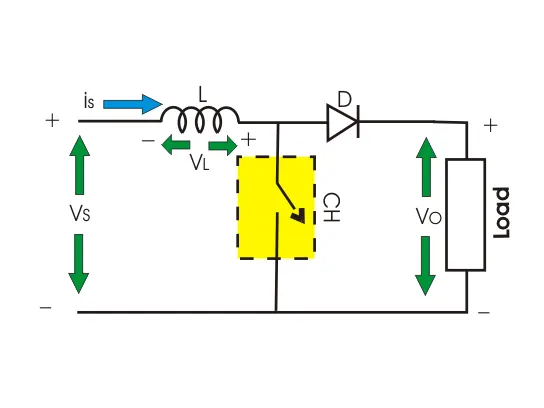
2) Step up Chopper or Boost Converter :
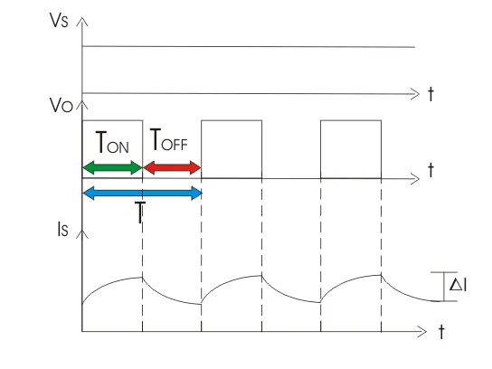
Step up chopper or boost converter is used to increase the input voltage level of its output side. Its circuit diagram and waveforms are shown below in figure.
The inverter is usually found between Battery and the DC induction motor, this motor is directly connected to the wheels and is responsible for the traction. Incase of Regenerative braking, this motor functions as a generator by converting the mechanical energy (from the wheels & axles) to electrical energy which is then stored in the traction battery.
DC-DC converter takes the DC source from the traction battery. The output from this DC-DC converter is used to power all the other components of the EV/HEV like HMI, Headlamps, AC, etc.
2. An Electric Vehicle's powertrain with 72V battery pack in shown in the diagram below. The duty ratio for acceleration operation is 'd1' and for the braking operation the duty ratio is 'd2'.
The other parameters of the electric vehicle is given below,
Motor and Controller Parameters:
Rated Armature voltage= 72 V
Rated armature current= 400 A
Ra= 0.5Ω, KΦ= 0.7 Volt second
Chopper Switching frequency= 400 Hz
The vehicle speed-torque characteristics are given by the below equation
What is EV steady state speed if duty cycle is 70%?
Given Data:
- Rated Armature Voltage (V_rated) = 72 V
- Rated Armature Current (I_rated) = 400 A
- Armature Resistance (R) = 0.5 Ω
- Motor Constant (K_phi) = 0.7 Volt second
- Chopper Switching Frequency (f) = 400 Hz
- Duty Cycle (D) for acceleration operation = 70%
We need to calculate the steady-state speed (ω) of the electric vehicle.
-
Calculate Effective Voltage (V) during Acceleration:
- The effective voltage during acceleration can be calculated as: V = V_rated * D V = 72 V * 0.7 V = 50.4 V
-
Calculate Torque-Speed Characteristics of the Motor:
- The torque-speed characteristics of the motor can be described by the equation: T_m = (V / K_phi) - (R * ((V / K_phi) - ω)) / K_phi
-
Equate Tractive Effort and Resistive Forces:
- In steady-state, the tractive effort (T_v) should balance the resistive forces (rolling resistance and drag force): T_v = T_resistive
-
Calculate Rolling Resistance (T_rr) and Drag Force (T_drag):
- Use the given formulas for rolling resistance and drag force: T_rr = μ_rr * m * g T_drag = 0.5 * ρ * A * v^2 * Cd
-
Calculate Total Resistive Forces (T_resistive):
- T_resistive = T_rr + T_drag
-
Calculate Vehicle Torque-Speed Characteristics (T_v):
- T_v = T_resistive
-
Solve for Steady-State Speed (ω):
- Set T_m equal to T_v and solve for ω: (V / K_phi) - (R * ((V / K_phi) - ω)) / K_phi = T_resistive
Rolling Resistace,
Drag Force,
Tractive Effort,
Let,
Also ,we know that
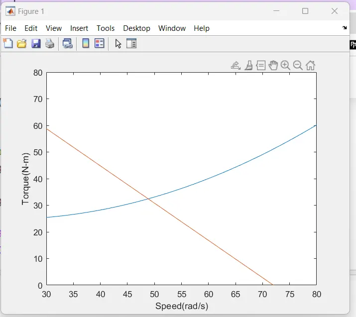
This is the torque speed characterstics of the vehicle.
Now the angular velocity
So,
Now putting all the values the above equation
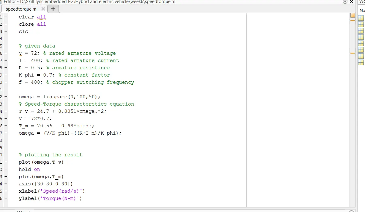
Since duty cycle is 70%,V = 72*0.7 = 50.4V
At steady state,
On equating both the sides we get,
4. Refer to the blog on below topic:
Induction Versus DC brushless motors by Wally Rippel, Tesla
Explain in brief about author’s perspective.
In the blog titled "Induction Versus DC Brushless Motors" by Wally Rippel, the author provides a perspective on the choice between induction motors and DC brushless motors in the context of electric vehicles. Here's a brief summary of the author's perspective:
-
No One-Size-Fits-All Approach: The author begins by drawing a parallel between the variety of internal combustion engines available for gas-powered vehicles and the diversity of electric motors for electric vehicles. Just as there is no single best internal combustion engine type, there is no one best electric motor type. The choice depends on various factors, including price and performance.
-
Introduction to DC Brushless and Induction Motors: The author explains the fundamental differences between DC brushless and induction motors:
-
DC Brushless Motors: These motors have rotors with permanent magnets that generate a DC magnetic field. An inverter controls the magnitude and polarity of the stator currents to produce torque efficiently. DC brushless motors require inverters for operation.
-
Induction Motors: These motors have stator windings that create a rotating magnetic field. The rotor has no magnets but instead has shorted steel laminations. Currents induced in the rotor conductors produce torque. Induction motors can start under load directly from AC power without the need for an inverter.
-
-
Comparison of DC Brushless and Induction Motors:
-
DC Brushless: These motors generate less rotor heat, have high peak point efficiency, and can operate at unity power factor.
-
Induction Motors: They have adjustable magnetic fields, which allow for optimization of efficiency at different load levels. They may have a slight disadvantage in peak point energy efficiency but may have better average efficiency, especially in high-performance applications.
-
-
Cost Considerations: Permanent magnets used in DC brushless motors are expensive, while induction motors are more cost-effective. Additionally, induction motors may have lower inverter ratings and costs, especially for high-performance drives.
-
Control Complexity: Induction motors are more challenging to control due to complex control laws. Achieving stability across the entire torque-speed range and over temperature can be more difficult with induction motors compared to DC brushless motors.
-
Market Outlook: The author predicts that DC brushless drives will dominate in the hybrid and plug-in hybrid markets, while induction drives will maintain dominance in high-performance pure electric vehicles. However, as hybrids become more electrically intensive and performance levels increase, both technologies may coexist in the electric vehicle market.
In summary, the author emphasizes that the choice between induction and DC brushless motors depends on various factors, including the specific application and performance requirements of electric vehicles. Each technology has its advantages and limitations, and the future may see both technologies coexisting in the electric vehicle industry.