Week-6 Challenge: EV Drivetrain
AIM :
- The types of power converter circuits are employed in electric and hybrid electric vehicle.
- What is EV steady state speed if duty cycle is 70% and the other parameters of the electric vehicle is given.
- Explain in brief about author’s perspective.
DESCRIPTION :
1. The types of power converter circuits are employed in electric and hybrid electric vehicle.
POWER CONVERTERS :
In electrical engineeing, power engineering and the electric power industry, power conversion is converting electric energy from one form to another such as converting AC and DC or changing the voltage or frequency or some combination of these. A power converter is an electrical or electro-mechanical device for converting electrical energy. This could be as simple as a transformer to change the voltage of AC power, but also includes far more complex systems.
TYPES OF POWER CONVERTER CIRCUITS :
Depending on the type of function performed, power electronic converters are categorized into following types.
- AC-DC Converter : Rectifier.
- DC-DC Converter : Chopper
- DC-AC Converter : Invertor.
Usually AC motors are used in HEVs or EVs for traction and they are fed by inverter and this inverter is fed by DC-DC converter.
DC-DC Converter: (CHOPPER)
The main dc-dc converter changes dc power from an on-board 200-800V high voltage battery into lower dc voltages (48V or 12V) to power headlights, interior lights, wiper and window motors, fans, pumps and many other systems within electric vehicles (EV) and hybrid electric vehicles (HEV). This high voltage to low voltage (HV-LV) dc-dc converter is often referred to as an auxiliary dc-dc, or Auxiliary Power Module (APM).
DC-DC Converter is responsible for Stepping up and stepping down the input voltage. DC-DC converters in an electric vehicle may be classified into unidirectional and bidirectional converters.
Unidirectional DC-DC converters connected to various onboard loads such as sensors, controls, entertainment, utility, and safety equipments. They are also used in DC motor drives and electric traction.
Bidirectional DC-DC converters find applications in places where battery charging, regenerative braking, and backup power are required. The power flow in a bidirectional converter is usually from a low voltage end such as a battery or a supercapacitor to a high voltage bus and is referred to as boost operation.
The Converters are classified as :
- Buck Converter
- Boost Converter
- Buck - Boost Converter
BUCK Converter:
The buck converter is step down converter and produces a lower average output voltage than the dc input voltage.
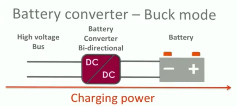
Here from the high voltage bus, it it stepped down and given to the battery where it is getting charged. Hence it is used for regenerative braking.
BOOST Converter:
The output voltage is always greater than the input voltage.'
BUCK-BOOST Converter:
The output voltage can be either higher or lower than the input voltage.
The amount of power flow between the input and the output can be controlled by adjusting the duty cycle (ratio of on/off time of the switch). Usually, this is done to control the output voltage, the input current, the output current, or to maintain a constant power.
DC-AC Converter: (INVERTERS)
An inverter is a device that converts DC power from the battery to AC power used in an electric vehicle motor. Inverters have taken a prominant role in the modern technological world due to sudden rise of electrical cars and renewable energy technologies. Inverts Dc power to AC power they are also used in uninterruptable power supplies control of electrical machines and active power filtering.
2. EV steady state speed if duty cycle is 70% and the other parameters of the electric vehicle is given.
Given data
An Electric Vehicle's powertrain with 72V battery pack in shown in the diagram below. The duty ratio for acceleration operation is 'd1' and for the braking operation the duty ratio is 'd2'.
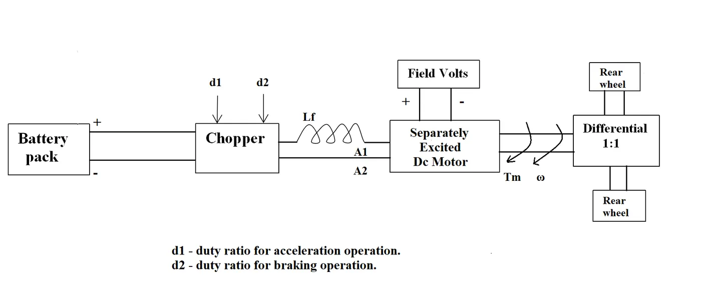
The other parameters of the electric vehicle is given below,
Motor and Controller Parameters:
Rated Armature voltage= 72 V
Rated armature current= 400 A
Ra= 0.5Ω, KΦ= 0.7 Volt second
Chopper Switching frequency= 400 Hz
The vehicle speed-torque characteristics are given by the below equation

Solution

Avg Voltage = 72 V * 0.7
Avg Voltage = 50.4 V
With the calculated Avg Voltage we can calculate the Torque and Speed Characteristics of DC Motor.
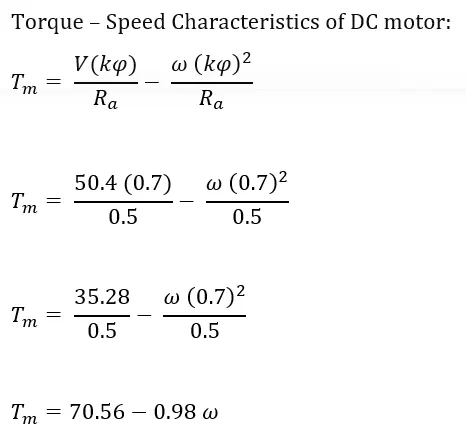
Tm denotes the Torque of the DC motor.
Now compare both the Torque Speed characteristics of DC motor and the vehicle.
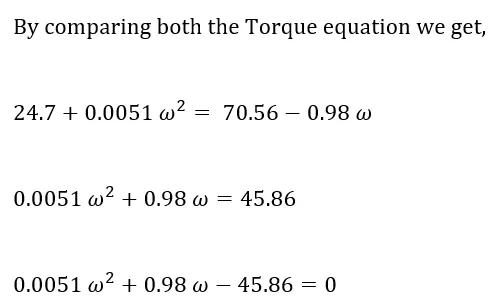
An Quadratic Equation is formed. To solve this,
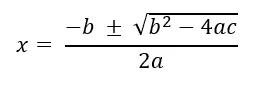
Equation is used to find the omega.
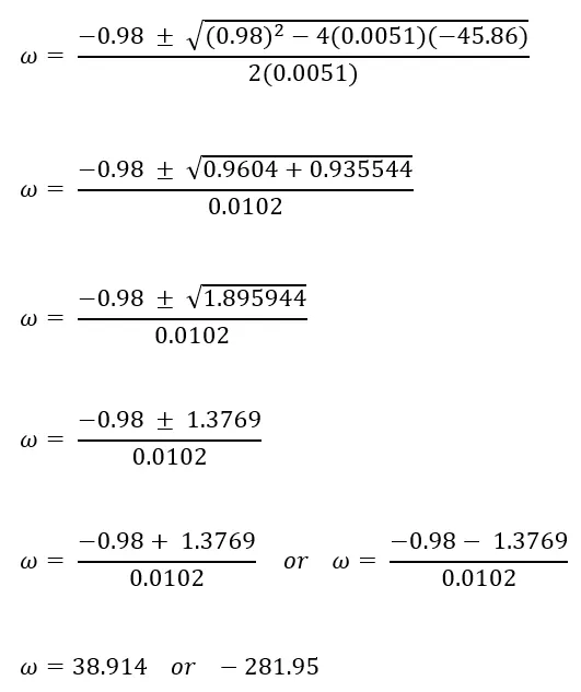
Here the vehicle's motion is in the forward direction so we are considering the positive value, thus the EV steady speed is 38.914 rad/s, If the duty cycle is 70%.
3. Induction Versus DC brushless motors by Wally Rippel, Tesla
AUTHOR : WALLY RIPPEL
Wally Rippel is a long-time proponent of electric vehicles. Prior to joining Tesla Motors, he was an engineer at AeroVironment, where he helped develop the EV1 for General Motors. Wally has also worked for the Jet Propulsion Laboratory on electric vehicle battery research, among other projects. In 1968, as a Caltech undergraduate student, he built an electric car (a converted 1958 Volkswagen microbus) and won the Great Transcontinental Electric Car Race against MIT.
AUTHOR'S PERSPECTIVE
In that odious world of gas powered vehicles, engines are not all alike. One would have thought that, years ago, someone would have figured out which was best. That would have ended all the choices and thereafter only the one best engine type would be in production.
With the above statement, Author starts his blogpost and tells us there is no best engine of all. It depends on the price and performance and various factors. No engine can be superior to all other that is not one engine can fulfill all the requirements. He aslo discussed about the replacement of Lead with Lithium in battery and DC by eitheir DC brushless or Induction.
Then Willey is giving a closer look on two technologies namely, DC Brushless and Induction. Like how do they work? What differentiates them? And what do they have in common? He starts with DC Brushless.
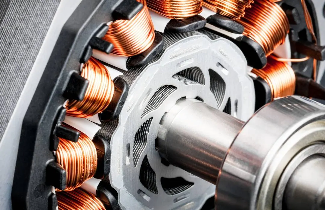
DC BRUSHLESS:
INDUCTION:
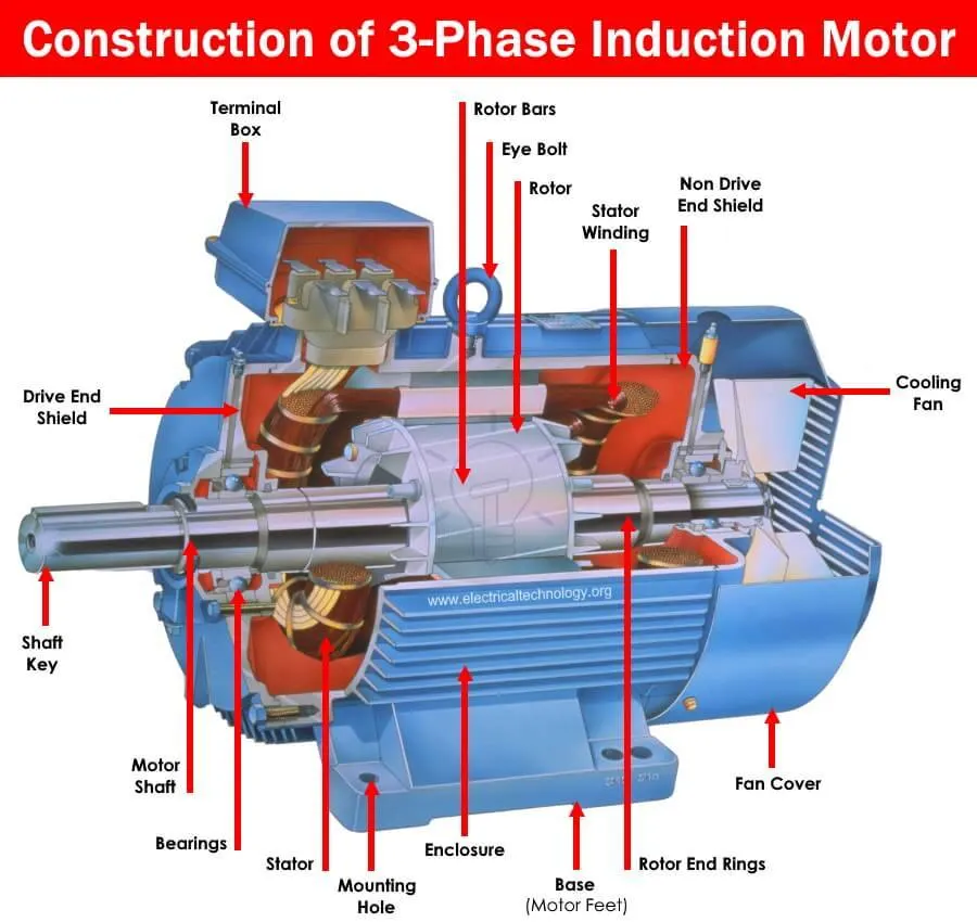
He also tells that the conversion of electrical to mechanical energy is optimally efficient in DC brushless motor and also tellus the advantage of induction motor like the motor has the ability to start under load. He also shares the reason for success is that induction motors are directly compatible with conventional utility power. Now on the limitations of induction motor.
- They cannot operate from DC, AC is a must.
- Shaft speed is proportionate to line frequency. Hence, when used with utility power, they are constant speed machines.
- When operated from utility power, they have limited starting torque and somewhat limited running peak torque capabilities, when compared to DC type machines.
- More difficult to control. The control laws are more complex and difficult to understand.
He aslo tells us the advantage of induction over DC brushless is that, the induction machine when operated with a smart inverter has an advantage over a DC brushless machine – magnetic and conduction losses can be traded such that efficiency is optimized. This advantage becomes increasingly important as performance is increased. With DC brushless, as machine size grows, the magnetic losses increase proportionately and part load efficiency drops. With induction, as machine size grows, losses do not necessarily grow
He also discussed about the losses in the motors. As he said in the introduction, he concludes with the same point. Still no Winner.
Conclusion:
Willey concludes by saying that DC brushless drives will likely continue to dominate in the hybrid and coming plug-in hybrid markets, and that induction drives will likely maintain dominance for the high-performance pure electrics.