Week-6 Challenge: EV Drivetrain
Aim : Which types of power converter circuits are employed in electric and hybrid electric vehicle?
Explanation :
1 : AC to DC Converter (Rectifier) -
The prime source of electrical power coming from the grid is single/three-phase alternating current. While AC current is efficient for transmission purposes, many devices, drives, and electronic
equipment require DC power supply that is fulfilled using rectifiers. A rectifier takes ac and converts it to DC. The rectifier is the most popular type of power electronics converter.
2 : DC to AC Converter (Inverter) -
An inverter or dc to ac converter takes dc power supply from the battery and converts it to ac. The process of inversion (dc to ac conversion) is particularly employed with battery banks in
uninterruptible power supply systems and in solar power systems.
3 : AC Voltage Regulator -
An AC voltage regulator is an AC to AC converter that takes AC voltage at one level and provides AC voltage at other amplitude. Such converters are comprised of triac, thyristors, or SCR, GTO’s,
IGBT’s or MOS controlled thyristors.
4 : DC to DC Converter -
A DC to DC converter (also known as chopper) is used for matching source voltage level with the component voltage level. They are further classified into three classes.
(i). Buck converter: A converter which provides output voltage less than the input.
(ii) Boost converter: A converter whose output is higher than the input.
(iii) Buck-Boost converter: A converter whose output can either be higher or lower than the input.
5 : AC/DC Converter -
An AC/DC Converter can convert AC to DC and DC to AC. Such converters have the capability to operate as an inverter as well as a rectifier.
6 : Frequency converter -
Many electrical drives and components require variable supply that differs from 50/60 Hz frequency coming from the grid. A frequency converter takes AC power supply at one frequency and converts
it to the required frequency. A frequency converter is also a type of AC to AC converter.
7 : Phase Converter -
A phase converter is also a type of AC to AC converter. It converts either single phase supply to three phase supply or three phase supply to single phase supply.
8 : Reactive power Converter -
A reactive power converter compensates the reactive power generated or consumed.
9 : Voltage Converter -
The voltage converter is a general terms. It can be a component which takes voltage as input and produces equivalent current. Many times AC to AC voltage converters are classified under generic
term voltage converter.
10 : Current converter -
A current converter takes current and produces equivalent voltage. Like the previous case, it is a generic term and can be extended to any class.
==============================================================================================================
Aim : An Electric Vehicle's powertrain with 72V battery pack in shown in the diagram below. The duty ratio for acceleration operation is 'd1' and for the braking operation the duty ratio is 'd2'.
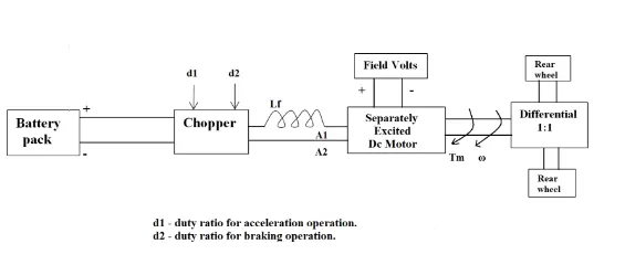
The other parameters of the electric vehicle is given below,
Motor and Controller Parameters:
Rated Armature voltage= 72 V
Rated armature current= 400 A
Ra= 0.5Ω, KΦ= 0.7 Volt second
Chopper Switching frequency= 400 Hz
The vehicle speed-torque characteristics are given by the below equation

What is EV steady state speed if duty cycle is 70%?
Solution :
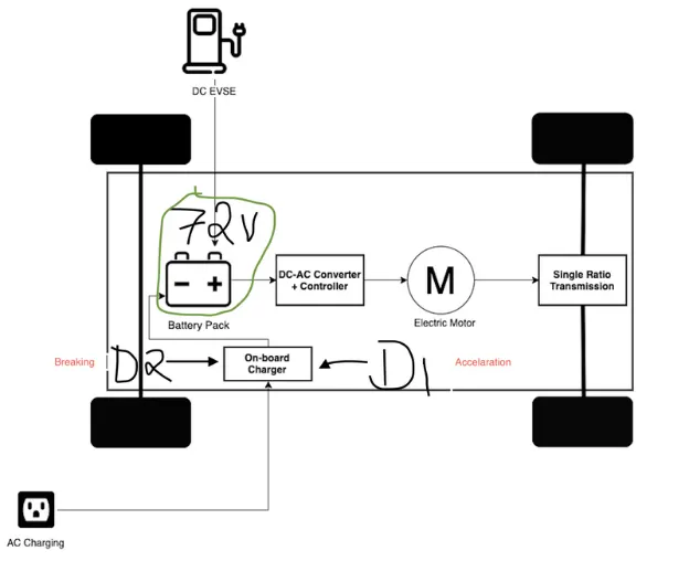
T= torque
V= armature voltage
R= resistance
W= speed rad/sec
Compare the two equations:
24.7 + 0.0051*w^2 = ((v*k)/R) - ((kA2)*w/R)
24.7 + 0.0051*w^2 = (72*0.7*0.7) /0.5 - (0.712/0.5)*W = 24.7 + 0.0051*w^2
70.56 - 0.98*W = 24.7 + 0.0051*W^2
(W^2 ) + (192.15*w) - (8992.15) = 0
(ax^2) + b x + c = 0
In order to find the roots use following formula
For a auadratic equation of the form ax^2+ bx + c=0 the solutions are
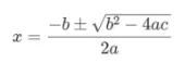
putting the valuues of equation in above formula we get the below result after solving
As the speed value can not be negative
W=38.95 rad/sec
==============================================================================================================
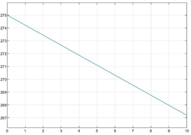
Aim : 3. Develop a mathematical model of a DC Motor for the below equation using Simulink.
ω = [ V/Kϕ ]-[Ra/Kϕ^2] * T
Material Required : Matlab simulink , subtract block , scope , product block, ramp block , constant block etc ..
SIMULINK BLOCK DIAGRAM OF THE ABOVE EQUATION
FILE IS ATTACHED BELOW (dotSLX)
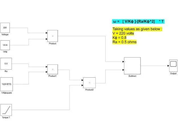
RESULT :
OUTPUT CURVE BETWEEN TORQUE SPEED CURVE FOR DC MOTOR VIA EQUATION
==============================================================================================================
Aim : 4. Refer to the blog on below topic:
Induction Versus DC brushless motors by Wally Rippel, Tesla
Explain in brief about author’s perspective.
My views on this above blog are :
The Walley Reppel perspective about brushless DC and induction motor,
1 : Who is Walley?
Walley is proponent of Electric Vehicle He was engineer at AeroVironment, Where is he helped to develop the EV for General motor He also worked in Jet propulsion
laboratory on electric vehicle battery research,among othe projects ,Proponent means someone who is in favor of something.
a : He said "One Size Does Not Fit All" he said in that odious world engines are of the different type. He said one would thought that ,year ago ,some was try to figure out which is best engine and that should be in production but his thought got failed there is no one is best one .with the different requirement there are different type of engine
b : He said the lead acid battery is replaced by the lithium and brush DC motor with Brushless DC motor or Induction motor.
c : Next he talks a closer look, he gives some closer look of the brushless DC motor and induction motor there technologies ,there working.
d : Then is told about the induction motor drives. he curiously told that stator of the both DC brushless and induction motor have three sets of "distributed windings" the only difference is in the rotor, induction motor has no magnet it contains steel laminations with buried periipheral conductors He describe working of induction motor that
Currents flowing in the stator winding produce a rotating magnetic field that enters the rotor.
2 : Next he is talking with the heading "Brushless or Induction"
He told that back 1990s all EV except one uses the DC brushless drives today all HEV using the DC brushless .Then he gave some comparison between DC brushless and induction motor
|
DC Brushless |
Induction motor |
|
less rotor heat is generated Rotor cooling is easier and peak point efficiency higher. operate at unity power factor |
power factor is about 85 %, peak point efficiency higher compare to DC Brushless |
|
require an absolute position sensor |
not require an absolute position sensor |
|
Average efficiency is low |
Average efficiency is high |
|
they are easy to control |
The control laws are more complex and difficult to understand, so difficult to control |
"Still No Winner", he describe that no one is best DC brushless or induction.
He concluded that both are the best as per the requirement.
Conclusion:
• we explain type of power converter used HEV and EV
• using formulas we got speed for vehicle
• we create the simulink model in simulink for the given dc motor equation mathematically .
• we have given the Explaination in brief about author's perspective about DC brushless motor and induction motor.