Week-6 Challenge: EV Drivetrain
- Which types of power converter circuits are employed in electric and hybrid electric vehicle?
- Power electronic technology deals with processing and controlling the flow of electrical energy in order to supply voltages and currents in a form that optimally suited for end user’s requirements.
- A power electronic converter uses power electronic components such as SCRs, TRIACs, IGBTs, etc. to control and convert the electric power. The main aim of the converter is to produce conditioning power with respect to a certain application.
- AC to DC = Rectifier
- DC to AC = Inverter
- DC to DC = Chopper
- AC to AC = Cycloconverter
AC-DC Converter:
- This AC-DC converter circuit used as a charger in EV and HEV to charge the battery by getting supply from Electrical network or Grid which is AC in nature so we need to convert into AC-DC for this we need AC-DC converter.
DC-AC Converter:
- This DC-AC converter circuit is also called as Rectifier circuit used in EV and HEV to give supply for induction motor by converting into DC power from battery module to AC power. This used in motor drive.
DC-DC Converter or Chopper circuit:
- This DC-DC converter circuit is also called as Chopper circuit used in EV and HEV for increase or decrease the DC voltage level for the requirements.
- This will be used for give supply for car infotainment systems like Auxillary accessoris, sound systems and dashboard.
- This DC-DC Converter or Chopper circuit are catagorised into two types they are:
Step-down Chopper circuit: This circuit is used for decrease the DC voltage from high to required level say for eg. 100V DC to 10V DC. So, this circuit is called Step-down chopper circuit.
Step-up Chopper circuit: This circuit is used for increase the DC voltage from low to required level say for eg. 10V DC to 100V DC. So, this circuit is called Step-up chopper circuit.
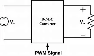
- An Electric Vehicle's powertrain with 72V battery pack in shown in the diagram below. The duty ratio for acceleration operation is 'd1' and for the braking operation the duty ratio is 'd2'.
The other parameters of the electric vehicle is given below,
Motor and Controller Parameters:
Rated Armature voltage= 72 V
Rated armature current= 400 A
Ra= 0.5Ω, KΦ= 0.7 Volt second
Chopper Switching frequency= 400 Hz
The vehicle speed-torque characteristics are given by the below equation
What is EV steady state speed if duty cycle is 70%?
Given Data:
- Vbat= 72 Volts
- d1=d2= 70%
- Ia=400 Amps
- Ra=0.5Ω
- KΦ= 0.7 Volt second
- f=400 Hz
Solution:
We know that The acual output of power converter Vo= Vbat*duty ratio
Vo= 72*70%
Vo= 50.4 V
We already know that DC motor speed torque charactristic equation.
T= (KΦ*V)/Ra - (KΦ^2*ω)/Ra
T= 50.4*0.7/0.5 - [(0.7^2)/0.5]ω
T=70.56 - 0.98ω------------ (1)
We already know that the vehicle speed-torque charactristissc equation is.
Tv=25.7 - 0.0051ω^2------------ (2)
Compare eqn. 1 and 2
70.56 - 0.98ω=25.7 - 0.0051ω^2
0.0051ω^2+0.98ω-45.86=0------------ (3)
Now divid the equation 3 by 0.0051 on both side.
ω^2+192.15ω-8992.15=0------------ (4)
The above equation 4 is in quadratic form
so we know that ω =[−b±√b^2−4ac]/2a or ω =[−b±sqrt(b^2−4ac)]/2a
ω =[-192.15±sqrt(192.15^2−4(1*-8992.15)]/2(1)
ω =[-192.15±sqrt(36921.62+35968.6)]/2
ω =[-192.15±269.98]/2
ω =[-192.15+269.98]/2 & ω =[-192.15-269.98]/2
ω = 38.91 & ω =-231.065
- The steady state speed of EV at 70% duty cycle ratio is 38.91 rad/sec.
- Develop a mathematical model of a DC Motor for the below equation using Simulink.
[Math Processing Error]ω= V/K[Math Processing Error]ϕ -Ra/K[Math Processing Error]ϕ^2 .T
DC Motor equation:
- ω">ωω= V/Kϕ">ϕϕ -Ra/Kϕ">ϕϕ^2 .T
Simulunk Model:
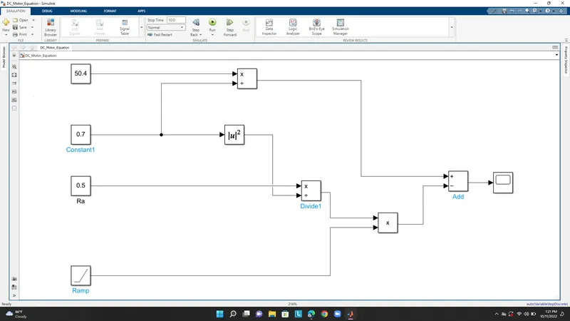
Scope Output:

- Refer to the blog on below topic:
Induction Versus DC brushless motor by Wally Ripple, Tesla
Explain in brief about author’s perspective.
Wally Ripple:
Wally Ripple is a long-time proponent of electric vehicles. Prior to joining Tesla Motors, he was an engineer at Aeroenvironment, where he helped develop the EV1 for General Motors and was featured in the documentary movie, Who Killed the Electric Car? Wally has also worked for the Jet Propulsion Laboratory on electric vehicle battery research, among other projects. In 1968, as a Caltech undergraduate student, he built an electric car (a converted 1958 Volkswagen microbus) and won the Great Transcontinental Electric Car Race against MIT.
Initially the author comparing this drives with engine by giving one example choosing one best engine type for all the needs is too difficult. Why becuase there is no one best engine type it depends upon the personal requirements,price and performance needed.
This is also true for a electric drives. From this the author conclude one drive and one engine is not fit for all.
Induction Motor
- An induction motor (also known as an asynchronous motor) is a commonly used AC electric motor In an induction motor, the electric current in the rotor needed to produce torque is obtained via electromagnetic Induction from the rotating Magnetic Filed of the stator winding. The rotor of an induction motor can be a squrriel cage motor or wound type rotor.
- Induction motors are referred to as ‘asynchronous motors’ because they operate at a speed less than their synchronous speed.
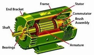
Single Phase Induction Motor
The types of single phase induction motors include:
- Split Phase Induction Motor
- Capacitor Start Induction Motor
- Capacitor Start and Capacitor Run Induction Motor
- Shaded Pole Induction Motor
Three Phase Induction Motor
The types of three phase induction motors include:
- Squrriel cage Induction motor
- Slip Ring Induction Motor
Advantages of induction Motor:
- Induction motors are simple and rugged in construction. Advantage of induction motors are that they are robust and can operate in any environmental condition
- Induction motors are cheaper in cost due to the absence of brushes, commutators, and slip rings
- They are maintenance free motors unlike dc motors and synchronous motors due to the absence of brushes, commutators and slip rings.
Disadvantages of Induction Motor:
- One of the main disadvantages of induction motors is that speed control of induction motors are difficult. Hence for fine speed control applications dc motors are used in place of induction motors. Due to advance in power electronics, variable frequency drives using induction motors are used in industries for speed control now a days.
- Induction motors always operate under lagging power factor and during light load conditions they operate at very worst power factor (0.2 to 0.4 lagging). Some of the disadvantages of poor power are increase in I2R losses in the system, reduction in the efficiency of the system. Hence some power factor correction equipments such as static capacitor banks should be placed nearto these motors to deliver the reactive power to them.
DC Brushless Motor:
A brushless DC motor (known as BLDC) is a permanent magnet synchronous electric motor which is driven by direct current (DC) electricity and it accomplishes electronically controlled commutation system (commutation is the process of producing rotational torque in the motor by changing phase currents through it at appropriate times) instead of a mechanically commutation system. BLDC motors are also referred as trapezoidal permanent magnet motors.
- Brushless DC motors (BLDC) have been a much focused area for numerous motor manufacturers as these motors are increasingly the preferred choice in many applications, especially in the field of motor control technology. BLDC motors are superior to brushed DC motors in many ways, such as ability to operate at high speeds, high efficiency, and better heat dissipation.
- They are an indispensable part of modern drive technology, most commonly employed for actuating drives, machine tools, electric propulsion, robotics, computer peripherals and also for electrical power generation. With the development of sensorless technology besides digital control, these motors become so effective in terms of total system cost, size and reliability.
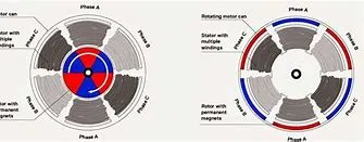
Working Principle od BLDC (Brushless DC Motor)
BLDC motor works on the principle similar to that of a conventional DC motor, i.e., the Lorentz force law which states that whenever a current carrying conductor placed in a magnetic field it experiences a force. As a consequence of reaction force, the magnet will experience an equal and opposite force. In case BLDC motor, the current carrying conductor is stationary while the permanent magnet moves.
Advantages of BLDC Motor
- High efficiency due to the use of permanent magnet rotor
- High speed of operation even in loaded and unloaded conditions due to the absence of brushes that limits the speed
- Smaller motor geometry and lighter in weight than both brushed type DC and induction AC motors
- Long life as no inspection and maintenance is required for commutator system
- Higher dynamic response due to low inertia and carrying windings in the stator
- Less electromagnetic interference
- Quite operation (or low noise) due to absence of brushes
Disadvantages of BLDC motor
- These motors are costly
- Electronic controller required control this motor is expensive
- Not much availability of many integrated electronic control solutions, especially for tiny BLDC motors
- Requires complex drive circuitry
- Need of additional sensors