Week-6 Challenge: EV Drivetrain
1. Which types of power converter circuits are employed in electric and hybrid electric vehicle?
1. Power converter circuits :
This technology deals with processing and controlling the flow of electrical energy in order to supply voltages and currents in a form that is optimally suited for the instruments.
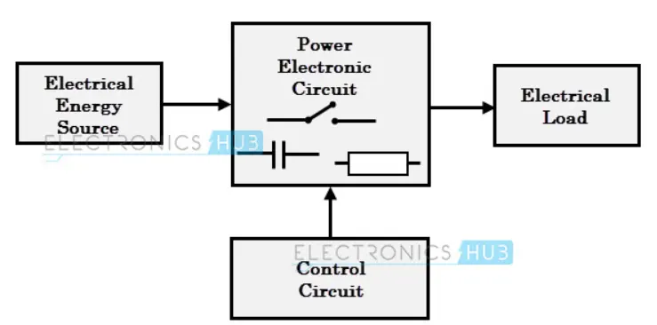
As shown in the above block diagram, it consists of an electrical energy source, a power electronic circuit, a control circuit and an electric load. This convertor changes one form of electrical energy to other forms of electrical energy. The power electronic circuit performs both the power part and the control part. The power part transfers the energy from source to load and it consists of power electronic switches, transformers, electric choke, capacitors, fuses and sometimes resistors. The control circuit regulates the elements in the power part of the converter. This block is built with a complex low power electronic that consists of either digital or analog circuit assembly.
Depending upon the functions performed, the following are the 4 different classifications
a) AC to DC converter which is called "Rectifier" - It converts AC into Unipolar DC current.
b) DC to AC converter which is called "Inverter" - It converts DC into AC of desired voltage and frequency.
c) DC to DC converter which is called "Chopper" - It converts High voltage DC to low voltage DC (Step down) or Low voltage DC to High voltage DC (Step up)
d) AC to AC converter which is called "Cycloconverter" - It converts the AC of the desired frequency and desired voltage magnitude from the AC supply.
Except for the AC to AC converter the other 3 are predominantly used in both the HEV and EV.
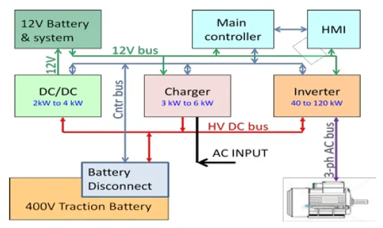
AC to DC converter (Rectifier) this used for charging the traction battery. Because the source of current is AC and the voltage stored in the traction Battery is DC.
The DC current from the Battery is then transmitted to 2 different converters, DC-AC converter (Inverter) and DC-DC converter (Chopper).
The inverter is usually found between Battery and the DC induction motor, this motor is directly connected to the wheels and is responsible for the traction. Incase of Regenerative braking, this motor functions as a generator by converting the mechanical energy (from the wheels & axles) to electrical energy which is then stored in the traction battery.
DC-DC converter takes the DC source from the traction battery. The output from this DC-DC converter is used to power all the other components of the EV/HEV like HMI, Headlamps, AC, etc.
2. An Electric Vehicle's powertrain with 72V battery pack in shown in the diagram below. The duty ratio for acceleration operation is 'd1' and for the braking operation the duty ratio is 'd2'.
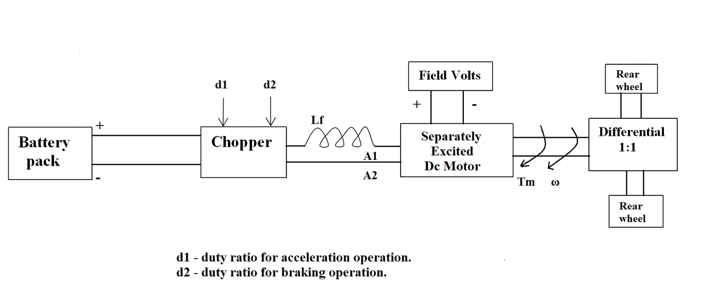
The other parameters of the electric vehicle is given below,
Motor and Controller Parameters:
Rated Armature voltage= 72 V
Rated armature current= 400 A
Ra= 0.5Ω, KΦ= 0.7 Volt second
Chopper Switching frequency= 400 Hz
The vehicle speed-torque characteristics are given by the below equation

What is EV steady state speed if duty cycle is 70%?
solution:
duty cycle = 70%
now, actual voltage =72*0.7=50.4v
the speed of the motor can be witten below,
ωm=v/kΦ -(ra/(kΦ)^2*Tm)
ωm=motor speed
v=armature voltage
kΦ=motor constant
ra=armature resistance
Tm=torque
redirecting the above equation with respect to torque
Tm=-ωm(kΦ)^2/ra+v*kΦ/ra
Tm=-ωm(0.7)^2/0.5+50.4*0.7/0.5
Tm=-0.98ωm+70.56---------equ 1
-----eqe 2
equating 1&2
-0.98ω+70.56=27.7+(0.0051)ω^2
0.0051ω^2+0.98ω-45.86=0
by 0.0051
ω^2+192.16 ω-8992.16=0
on solving we get
ω=38.91rad/s speed of the ev
EV steady state speed if duty cycle is 70% is 38.90rad/s
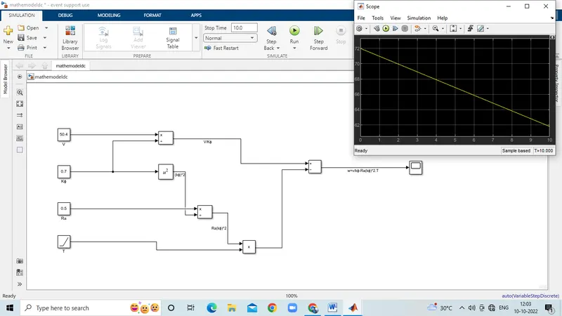
3. Develop a mathematical model of a DC Motor for the below equation using Simulink.
ω= V/Kϕ -Ra/Kϕ^2.T
4. Refer to the blog on below topic:
Induction Versus DC brushless motors by Wally Rippel, Tesla
Explain in brief about author’s perspective.
The author writes this blog to entail the differences between the two most commonly used motor drives in the automobile industry. The DC brushless motor drive and the induction motor drive. Rippel goes into detail about the differences in construction, working, and cost between the two drive types. However, with what he has written, he has not arrived at the conclusion that one type is better than the other. In the last lines of the opening paragraph, Rippel writes that "there is no one best engine type" and that it is all a matter of personal preference when it comes to choosing an engine. It is in this same regard that he ends the blog stating that there is still 'no winner' when it comes to motor drive selection either. In spite of both motor drive types having similarities, they also have their benefits and drawbacks.
For DC brushless drives, we are told that their construction implements 2 or more permanent magnets at the rotor to generate a DC magnetic field. It also consists of a stator core (made up of thin, stacked laminations). It also uses an inverter for the current control, meaning that it cannot run on a DC power supply as the current direction has to be changed repeatedly to maintaining constant torque.
For Induction drives, their rotor has no magnets but instead stacked steel laminations with buried peripheral conductors which form a 'shorted structure'. It is the current in the stator windings that generates a rotating magnetic field that interacts with the rotor.
Induction motors can be used directly with power from the mains and do not require an inverter to start the drive and generate the starting torque. It has the ability to start under the mains load applied. However, DC brushless drives cannot do the same. They cannot generate a starting torque when connected to a mains power supply. They require an inverter to do this.
Induction motor drives cannot run on a DC power supply and are solely dependent on AC power supply. Also, when they are connected to a 3 phase mains supply, the rotor rotates at a constant speed and also they have a limited starting torque as well as peak torque. In order to rectify this an inverter can be used to operate the induction drive from a DC power supply or a battery. Also, if the inverter frequency is varied, then the constant speed is no longer an issue - it can be varied.
- Difference between DC Brushless Motor and Induction Motor given below:-
| S.NO. | DC BRUSHLESS MOTOR | INDUCTION MOTOR |
| 1 | DC Supply | AC Supply |
| 2 | Require position sensor | Require speed sensor |
| 3 | The torque generated due to interaction of rotor and stator magnetic field | Stators rotating magnetic field induces a current in rotor laminations, which interact with the stator magnetic field and produce torque |
| 4 | The rotor includes two or more permanent magnets to generate a magnetic field | The rotor includes stacked steel laminations with shorted peripheral conductors for induced magnetic field |
| 5 | Less Rotor heat generated, easier rotor cooling, and higher peak point efficiency. Power factor up to 100% can be reached | Rotor cooling is difficult. Maximum power factor that can be achieved in 85% |
| 6 | Permanent magnets are costly and ferromagnets cannot be brought near the motor | Difficult to control, complex control laws for inverters |
| 7 | As for size increases, losses increase, and part-load efficiency decreases | As for size increases, losses remain approximately the same |
| 8 | The magnetic field strength cannot be adjusted thus only single torque output can be obtained | The magnetic field strength can be varied as a function of voltage supply and frequency for optimized torque output. |
| 9 | Preferred for HEV | Preferred for pure EV for high performance |
CONCLUSION:-
- Types of Converters used in HEV's and EV's vehicles
- To find the velocity using the Torque-Speed expression.
- To create the Simulink modal of given equations.
- To get to know about the induction and DC motor and try to find the best options available.
REFERENCES:-