Study about EV Drivetrain
Aim
To study about power converters and steady state speed of hybrid and electric vehicles
Objectives
- To explain the types of power converter circuits employed in electric and hybrid eclectic vehicle.
- To find out the steady state speed of an electric vehicle
- To explain Tesla’s blog on the topic induction versus DC brushless motors
Explanations
1. Power Converters
A power converter is made of high power and fast acting semi conductor devices such as bipolar junction transistor (BJT), metal oxide semiconductor field effect transistor (MOSFET), insulated gate bipolar transistor (IGBT), silicon controlled rectifier (SCR), gate turn off SCR (GTO), and MOS controlled thyristor (MCT). These solid state devices configured in a certain circuit topology function as an on off electronic switch to convert the fixed supply voltage into variable voltage and variable frequency supply. All of these devices have a control input gate or base through which the devices are turned on and off according to the command generated by the controller.
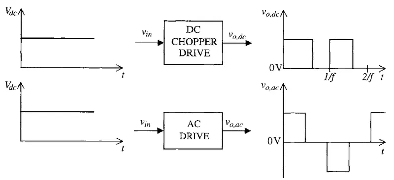
There are mainly two types of converters. One of them converts the form of the signal and the other one changes the level of the signal. These two types are again classified into four. They are listed below.
i) DC to AC converters
It is commonly known as inverters. They are used in motor drive of electric vehicles. This electrical device converts electricity derived from a Direct Current (DC) source to Alternating Current (AC) of the type that can be used to drive a device or appliance. In solar power system, for example, the power stored by batteries charged by solar panels is converted to standard AC power by the inverter, which provides the power to plug in outlets and other standard 120 volt devices.
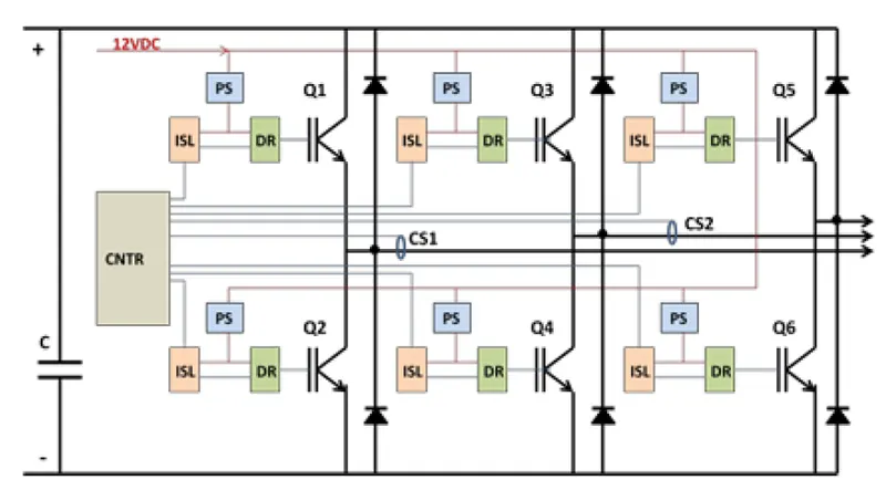
An inverter serves the same function in a hybrid or electrical vehicle (EV) and the theory of operation is relatively simple. DC power, from a hybrid battery, for example, is fed to the primary winding in a transformer within the inverter housing. Through an electronic switch (generally a set of semiconductor transistors), the direction of flow of current is continuously and regularly flip flopped (the electrical charge travels into the primary winding, then abruptly reverses and flows back out). The in and out flow of electricity produces AC current in the transformer’s secondary winding circuit. Ultimately, this induced alternating current electricity provides power for an AC load. For example, an EV’s electric traction motor. Most common topology of inverter in EV is three phase bridge. It is represented below.
ii) AC to DC converters - They are also called rectifiers and commonly used in charging applications of electric vehicles. Rectifier is similar to an inverter except that it does the opposite, converting AC power to DC power.
iii) DC to DC converters – This converter is named as chopper. It changes the voltage level of DC current according to the situation. More properly called a voltage converter. There are two types of this converter. First one is named as step up converter which increases the voltage and second one named step down converter which does the opposite. The most common use of a converter is to take relatively low voltage source and step it up to high voltage for heavy duty work in a high power consumption load, but they can also be used in reverse to reduce voltage for a light load source.
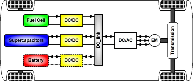
iv) AC to AC converters - It is commonly used in fan regulators. This converter doesn’t have any application in electric vehicle. It is same as the voltage converter. The only difference is that, this operates on AC power source.
2. Steady state speed
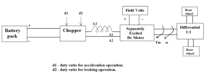
An electric vehicle’s power train with 72V battery pack is shown in the diagram below. The duty ratio for acceleration operation is ‘d1’ and for the breaking operation the duty ratio is ‘d2’.
The other parameters of the electric vehicle are given below. The motor control parameters are:
Rated armature voltage = 72 V Rated armature current = 400 A Ra = 0.5 Kφ = 0.7 V/S Chopper switching frequency = 400 Hz
The vehicle speed torque characteristics are given by the below equation

What is EV steady state speed if duty cycle is 70%?
We know an equation of torque from speed torque characteristics of DC machine and it is given below.
Te = [(VA – Kφ*W)/RA]*Kφ
Where the variables are armature winding resistance RA, armature voltage (VA), developed motor torque (Te), shaft speed (W), armature linking flux (φ) and machine constant (K).
Motor voltage = armature voltage * duty cycle = 72 * 0.7 = 50.4 V
Now substituting values will obtain, Te = [(50.4-0.7*W)/0.5]*0.7 = 70.56 – 0.98*W
And Tv = 24.7 + (0.0051) * W2
Equating the two equations will result in the following equation
70.56 – 0.98*W = 24.7 +( 0.0051) * W2
W2 + 192.151*W – 8992.156 = 0
Now this is a quadratic equation and the solution of this equation will have two values.
W = 38.92 & - 231.1
Hence the steady state value of EV is 38.9
3. Blog review
Here we have to refer a blog on the topic induction versus DC brushless motors. Link for the blog is given below.
https://www.tesla.com/blog/induction-versus-dc-brushless-motors
Now we must explain this in brief about author’s perspective. The author is Wally Rippel.
There are different types of engine in this world. According to the taste of drivers, the performance will get change. This scenario is same in electric vehicles also. According to time and developments, the led acid batteries, DC brush motors and contactor controllers became out dated. Lead has been replaced by lithium and DC by either DC brushless or induction. Contactors meanwhile have given way to modulating inverters. This will also get outdated and will give way to new technologies. Induction and brush less machine will have a very tight competition for this.
In case of DC brush less machine, the rotor includes permanent magnets and this magnetic field enters stator core and produce a torque interaction between rotor and stator. This machine needs inverter for its efficient working. Unlike DC brushless rotor, the induction rotor has no magnets. Instead it has stacked steel laminations with buried peripheral conductors. Current flowing in the stator produces a rotating magnetic field that enters the rotor. The produced current interacts with original magnetic field to produce desired torque.
Induction motor is directly compatible with conventional utility power is the main reason or success. Brushless motor produces no stating torque when directly connected to fixed frequency utility power because they need an inverter. Induction motor only works in AC. Adding an inverter and some feedback loops will make induction motor capable of competing with DC brushless for vehicle applications.
Today all hybrids are powered by DC brushless drives. Difference between DC and inverters are that both have different control codes. In DC less rotor heat is produced. It can also operate at unity power factor whereas the best power factor for the induction drive is about 85 percent. Induction machines are less costly but difficult to control. Magnetic flux in brushless machines is controllable and induction is better when it is used with a smart inverter.
In conclusion, DC brushless drives will likely continue to dominate in hybrid markets and induction drives will likely maintain dominance for high performance pure electrics. Hopefully induction and DC brushless live and work side by side during the coming golden era of electric vehicles.
Conclusions
Studies regarding power converters were conducted and a numerical problem regarding steady state speed was solved. A blog review was also conducted on the topic induction versus DC brushless motors
References
[1] ELECTRIC and HYBRID VEHICLES Design Fundamentals, Iqbal Husain, 2003, CRC Press LLC
[2] Electric and Hybrid Vehicle Power Electronics Efficiency Testing and Reliability, Joe Drobnik et al, EVS27 International Battery, Hybrid and Fuel Cell Electric Vehicle Symposium