Week-6 Challenge: EV Drivetrain
Q1. Which types of power converter circuits are employed in electric and hybrid electric vehicle?
Answer:
Power Converter:
- A power converter is an electrical circuit that changes the electric energy from one form into the desired form optimized for the specific load. A converter may do one or more functions and give an output that differs from the input. It is used to increase or decrease the magnitude of the input voltage, invert polarity, or produce several output voltages of either the same polarity with the input, different polarity, or mixed polarities such as in the computer power supply unit.
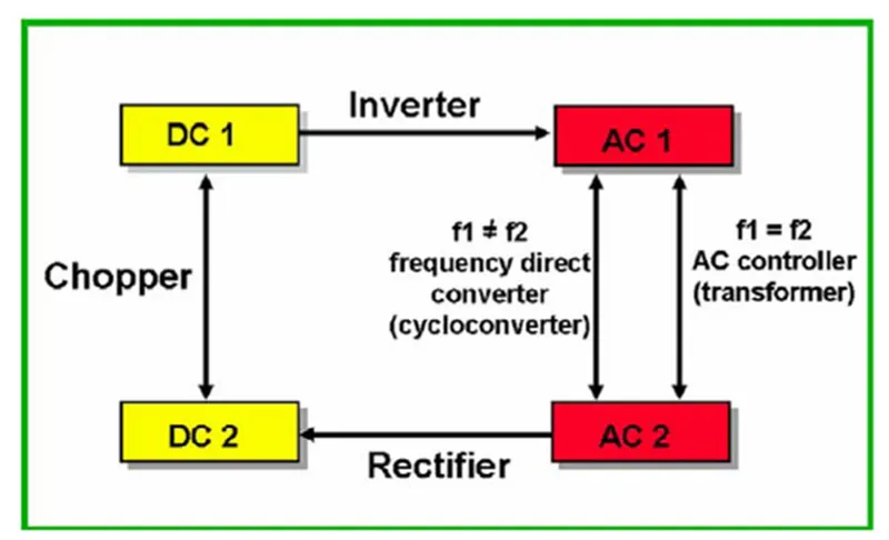
- The converter acts as the link or the transforming stage between the power source and the power supply output. There are several kings of converters based on the source input voltage and the output voltage and these falls into four categories namely the AC to DC converter known as the rectifier, the AC to AC clycloconverter or frequency changer, the DC to DC voltage or current converter, and the DC to AC inverter.
- The converter uses non linear components such as the semiconductor switches, and linear reactive components such as the inductors, transformers and capacitors for intermediate energy storage as well as current and voltage filtering. The size, weight and cost of the converter are largely determined by these components.
DC –DC Coverter:
- DC-DC converters are high-frequency power conversion circuits that use high-frequency switching and inductors, transformers, and capacitors to smooth out switching noise into regulated DC voltages. Closed feedback loops maintain constant voltage output even when changing input voltages and output currents. At 90% efficiency, they are generally much more efficient and smaller than linear regulators. Their disadvantages are noise and complexity.
- There three basic converter circuits that are widely used in DC to DC converters are the buck, boost, and the buck and boost. These configurations are the most used topologies due to their simplicity and use of fewer components. Each has its advantages and drawbacks which determines the suitability for any specific application.
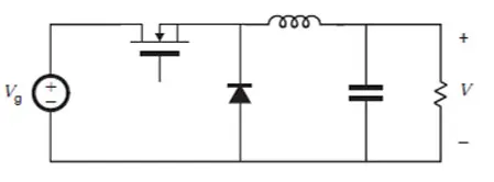
1.Buck Converter: A buck converter steps a voltage down, producing a voltage lower than the input voltage. A buck converter could be used to charge a lithium ion battery to 4.2 V, from a 5 V USB source.
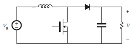
2.Boost Converter: A boost converter steps a voltage up, producing a voltage higher than the input voltage. A boost converter could be used to drive a string of LEDs from a lithium cell, or provide a 5 V USB output from a lithium cell.
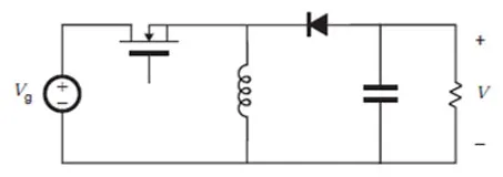
3.Buck-Boost Converter: A buck-boost converter steps a voltage up or down, producing a voltage equal to or higher or lower than the input voltage. A buck boost could be used to provide a 12 V output from a 12 V battery. A 12V battery’s voltage can vary between 10 V and 14.7 V. A buck boost could also power an LED from a single cell. An LED forward drop is as high as 3 V. A lithium battery cell can vary between 2.5 and 4.2 V. There are buck-boosts that produce positive and negative voltages.
DC-AC Converter:
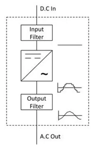
- DC-to-AC Convertersare one of the most important elements in power electronics. This is because there are a lot of real-life applications that are based on these conversions. The electrical circuits that transform Direct current (DC) input into Alternating current (AC) output are known as DC-to-AC Converters or Inverters. They are used in power electronic applications where the power input pure 12V, 24V, 48V DC voltage that requires power conversion for an AC output with a certain frequency.
- These are used in numerous applications, including PV systems, battery storage systems, traction drives, variable speed drives, etc. Converting from DC to AC is more complicated because the circuit needs some kind of oscillatorthat reverses the current direction at the required frequency. Most inverters rely on resistors, capacitors, transistors, and other circuit devices for converting DC Voltage to AC Voltage.
AC-DC Converter:
- AC to DC Converters are one of the most important elements in power electronics. This is because there are a lot of real-life applications that are based on these conversions. The electrical circuits that transform alternating current (AC) input into direct current (DC) output are known as AC-DC converters. They are used in power electronic applications where the power input a 50 Hz or 60 Hz sine-wave AC voltage that requires power conversion for a DC output.
- The process of conversion of AC current to dc current is known as rectification. The rectifier converts the AC supply into the DC supply at the load end connection. Similarly, transformers are normally used to adjust the AC source to reduce the voltage level to have a better operation range for DC supply.
- In alternating current, the current changes direction and flows forward and backward. The current whose direction changes periodically is called an alternating current (AC). It has non-zero frequency. It is produced by AC generator, dynamo, etc.
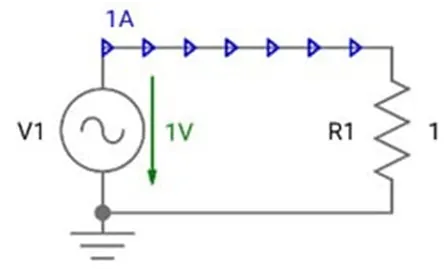
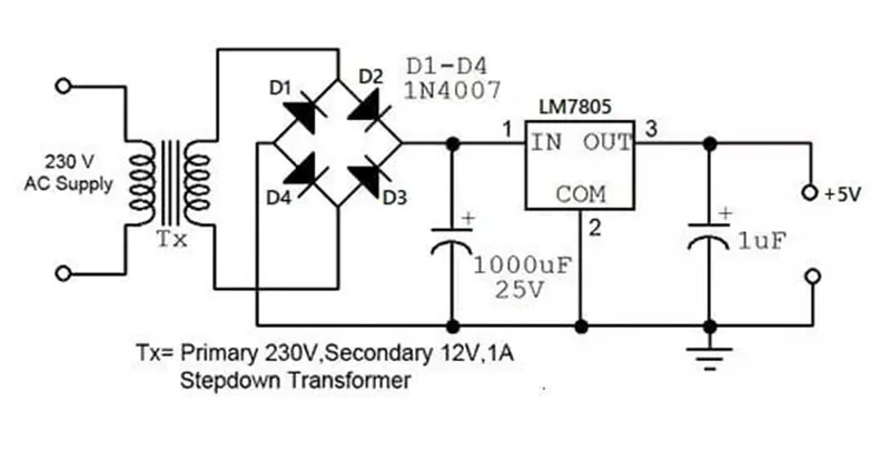
- AC to DC Power Converter Circuit
The rectifier converts the AC supply into the DC supply at the load end connection. There are different types of rectifiers, such as half-wave, full-wave, and bridge rectifiers.
Q2. An Electric Vehicle's powertrain with 72V battery pack in shown in the diagram below. The duty ratio for acceleration operation is 'd1' and for the braking operation the duty ratio is 'd2'.
Answer:
Given Data:
The other parameters of the electric vehicle is given below,
Motor and Controller Parameters:
Rated Armature voltage= 72 V
Rated armature current= 400 A
Ra= 0.5Ω, KΦ= 0.7 Volt second
Chopper Switching frequency= 400 Hz
The vehicle speed-torque characteristics are given by the below equation

Solution:
Duty cycle is 70%
Rated Armature voltage= 72 V
Actual Voltage = 72*0.7
= 50.4 V
We know,
Motor speed and torque relation is `T_m= V/R_a K∅- ω_m/R_a K∅^2`
Then put all the data , `T_m= 50.4/0.5 0.7- ω_m/0.5 〖0.7〗^2`
= `70.56 – 0.98ω_m` Eq -1
Then solve these two equation , 1 & 2
`70.56 – 0.98ω_m = 24.7^2 + (0.0051)ω^2`
`0.0051ω^2 + 0.98ω_m + 45.86 = 0`
After solving the quadratic equation we get,
`ω`= 38.86 Rad/sec and `ω`= -230.95 Rad/sec
So steady state speed of vehicle is 38.86 Rad/sec
Q3. Develop a mathematical model of a DC Motor for the below equation using Simulink.
ω= V/Kϕ -Ra/Kϕ^2 .T
Answer:
This equation is speed and torque equation of dc motor.
Explanation (How to create):
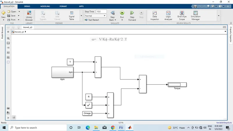
Step 1: First i took constant block name is ‘V’ .Then create a Kphi subsystem blocks .then both blocks connected with divide block.
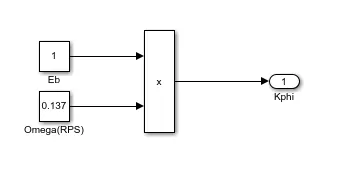
Step 2: Then create Armature resistance block and omega blocks and Kphi^2 block using constant block . then all the blocks connected with three port divide-multiplication blocks.
Step 3: Then two blocks connected with subtract block . then connected a display for output result.
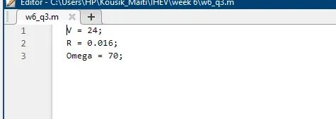
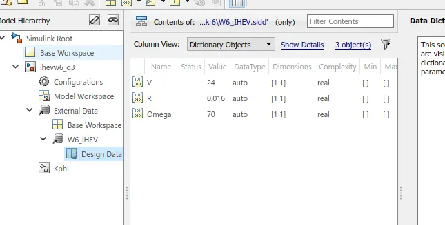
Step 4: Then create sldd for input variables. And create also base workspace block.
Q4. Refer to the blog on below topic:
Induction Versus DC brushless motors by Wally Rippel, Tesla
Explain in brief about author’s perspective.
Answer:
According to author’s perspective
- Author wally Rippel mention many of things in this document.
- Who Killed the Electric Car?is a 2006 American documentary film directed by Chris Paine that explores the creation, limited commercialization and subsequent destruction of the battery electric vehicle in the United States, specifically the General Motors EV1 of the mid-1990s. The film explores the roles of automobile manufacturers, the oil industry, the federal government of the United States, the California government, batteries, hydrogen vehicles and consumers in limiting the development and adoption of this technology.
- After a premiere at the 2006 Sundance Film Festival, it was released theatrically by Sony Pictures Classicson June 28, 2006. A follow-up documentary, Revenge of the Electric Car, was released in 2011
- The film deals with the history of the electric car, its modern development, and commercialization. The film focuses primarily on the General Motors EV1, which was made available for leasemainly in Southern California, after the California Air Resources Board (CARB) passed the zero-emissions vehicle (ZEV) mandate in 1990 which required the seven major automobile suppliers in the United States to offer electric vehicles in order to continue sales of their gasoline powered vehicles in California. Nearly 5000 electric cars were designed and manufactured by Chrysler, the Ford Motor Company, General Motors (GM), Honda, Nissan, and Toyota; and then later destroyed or donated to museums and educational institutions. Also discussed are the implications of the events depicted for air pollution, oil dependency, Middle East politics, and global warming.
- The film details the California Air Resources Board's reversal of the mandate after relentless pressure and suits from automobile manufacturers, continual pressure from the oil industry, orchestrated hype over a future hydrogen car, and finally the George W. Bush administration.
- One topic that arises when discussing alternative vehicle options is the practicality of electric vehicles. Specifically, investigating factors such as ownership costs - factoring in battery replacement, practicality issues, and environmental impacts help understand the real-world positives and negatives of electric vehicles. Proponents of Electric vehicles(EVs) and internal combustion engines like to talk past each other. Advocates for electric vehicles like to talk about zero driving emissions, and not having to go to gas pumps. Those in favor of internal combustion talk about battery replacement costs, and lack of range.
DC Brushless Motor:
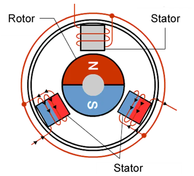
- As their name implies, brushless DC motors do not use brushes. With brushed motors, the brushes deliver current through the commutator into the coils on the rotor. So how does a brushless motor pass current to the rotor coils? It doesn’t—because the coils are not located on the rotor. Instead, the rotor is a permanent magnet; the coils do not rotate, but are instead fixed in place on the stator. Because the coils do not move, there is no need for brushes and a commutator.
- With the brushed motor, rotation is achieved by controlling the magnetic fields generated by the coils on the rotor, while the magnetic field generated by the stationary magnets remains fixed. To change the rotation speed, you change the voltage for the coils. With a BLDC motor, it is the permanent magnet that rotates; rotation is achieved by changing the direction of the magnetic fields generated by the surrounding stationary coils. To control the rotation, you adjust the magnitude and direction of the current into these coils.
Advantages of DC Brushless Motor:
- A BLDC motor with three coils on the stator will have six electrical wires (two to each coil) extending from these coils. In most implementations three of these wires will be connected internally, with the three remaining wires extending from the motor body (in contrast to the two wires extending from the brushed motor described earlier). Wiring in the BLDC motor case is more complicated than simply connecting the power cell’s positive and negative terminals; we will look more closely at how these motors work in the second session of this series. Below, we conclude by looking at the advantages of by BLDC motors.
- One big advantage is efficiency, as these motors can control continuously at maximum rotational force (torque). Brushed motors, in contrast, reach maximum torque at only certain points in the rotation. For a brushed motor to deliver the same torque as a brushless model, it would need to use larger magnets. This is why even small BLDC motors can deliver considerable power.
- The second big advantage—related to the first—is controllability. BLDC motors can be controlled, using feedback mechanisms, to delivery precisely the desired torque and rotation speed. Precision control in turn reduces energy consumption and heat generation, and—in cases where motors are battery powered—lengthens the battery life.
Induction Motor:
- An induction motor (also known as an asynchronous motor) is a commonly used AC electric motor. In an induction motor, the electric current in the rotor needed to produce torque is obtained via electromagnetic induction from the rotating magnetic field of the stator winding. The rotor of an induction motor can be a squirrel cage rotor or wound type rotor.
- Working Principle:
- We need to give double excitation to make a DC motor to rotate. In the DC motor, we give one supply to the stator and another to the rotor through brush arrangement. But in induction motor, we give only one supply, so it is interesting to know how an induction motor works.
- It is simple, from the name itself we can understand that here, the induction process is involved. When we give the supply to the stator winding, a magnetic flux gets produced in the stator due to the flow of current in the coil. The rotor winding is so arranged that each coil becomes short-circuited.
- The flux from the stator cuts the short-circuited coil in the rotor. As the rotor coils are short-circuited, according to Faraday’s law of electromagnetic induction, the current will start flowing through the coil of the rotor. When the current through the rotor coils flows, another flux gets generated in the rotor.
- Now there are two fluxes, one is stator flux, and another is rotor flux. The rotor flux will be lagging with respect to the stator flux. Because of that, the rotor will feel a torque which will make the rotor to rotate in the direction of the rotating magnetic field. This is the working principle of both single and three-phase induction motors.
Disadvantages of induction motor in EV /HEV Vehicle:
- Induction motor difficult to control then dc brushless induction motor.
- Induction motor cooling capability not so good then dc brushless motor
Similarity of DC brushless and Induction motor:
- Both DC brushless and induction drives use motors having similar stators. Both drives use 3-phase modulating inverters. The only differences are the rotors and the inverter controls. And with digital controllers, the only control differences are with control code. (DC brushless drives require an absolute position sensor, while induction drives require only a speed sensor; these differences are relatively small.)
Conclusion:
My conclusion is that DC brushless drives will likely continue to dominate in the hybrid and coming plug-in hybrid markets, and that induction drives will likely maintain dominance for the high-performance pure electrics. The question is what will happen as hybrids become more electrically intensive and as their performance levels increase? The fact that so much of the hardware is common for both drives could mean that we will see induction and DC brushless live and work side by side during the coming golden era of hybrid and electric vehicles.