Week-6 Challenge: EV Drivetrain
1. Which types of power converter circuits are employed in electric and hybrid electric vehicle?
ANSWER:-
Power electronic Converters:-
- In EV and HEV , the power electronic converters are considered as the key elements tht interface their power sources to the drivetrain of the EVs.
- In order to design highly effiicient converters for the EVs power system,advanced DC-DC & DC-AC & DC-DC Converters are required.
- we will see the usage of these converters now,
Three types of converters are widely used they are:-
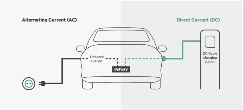
AC-DC CONVERTER(on board charger):-
- These type of converters are widely used in plug in hybrid electric vehicles(PHEV) & PEV .
- These vehicles gets a power input into battery which is normally a dc so, The input Ac is converted by using the AC-DC converter and then battery is charged and used for vehicle performance.
DC-DC CONVERTER:-
- DC-DC converters are used to interface the elements in the electric power train by bosting or chopping the voltage level.
- we can choose voltage variation of the devices and power of each blocks can be controlled.
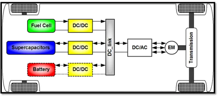
- this converter is depends upon the characteristics of top speed, acceleration time from 0 to 100 kmph ,weight,max torque and power profile(peakpower and continuous power)
DC-AC CONVERTER (inverter):-
- This converter converts the dc power into suitable ac voltage power for the machine model.
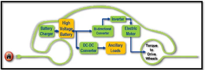
- The power output from battery is dc which the motor needs ac power at this situation we use this converter as an inverter.
2. An Electric Vehicle's powertrain with 72V battery pack in shown in the diagram below. The duty ratio for acceleration operation is 'd1' and for the braking operation the duty ratio is 'd2'.
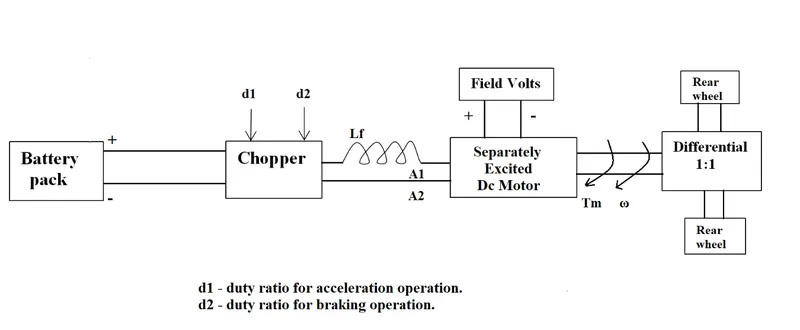
The other parameters of the electric vehicle is given below,
Motor and Controller Parameters:
Rated Armature voltage= 72 V
Rated armature current= 400 A
Ra= 0.5Ω, KΦ= 0.7 Volt second
Chopper Switching frequency= 400 Hz
The vehicle speed-torque characteristics are given by the below equation

What is EV steady state speed if duty cycle is 70%?
ANSWER:-
GIVEN PARAMETERS:-
- Battery pack voltage (V) = 72 v
- Rated armature current (Ia)= 400 A
- Armature resistance (Ra) = 0.5 ohms
- Motor Constant (Kpi)=0.7
- Chopper switching frequency =400 Hz
- Duty Cycle= 70 %
The vehicle output voltage (Vv) is given by:-
(Vv)= battery voltage (v) * duty cycle
(Vv)=72 * 0.70
Vehicle voltage (Vv) =50.4V
we know the torque of the vehicle can be given by:-
We assume (w=womega)
Tv= ((Vv- w.Kphi).Kphi) / Ra
Where ,
Tv= Vehicle torque (NM)
w= steady state speed of the vehicle
By substituting the values in the formula we get ,
- Tv= (((50.04 - 0.7 * w) 0.7)/(0.5))
- Tv = 70.56 - 0.98w
- Tv=24.7 + 0.0051 w^2
- By solving these two equations we get,
- 0.0051 w^2 + 24.7 w = 70.56 - 0.98w.
- we get a quadratic equation, we get
- 0.0051w^2 +0.98W -46.94 =0
By quadratic equation we get the two values w= 38.85 rad/s & w = 230.95 rad/s
We take the postive value: steady state speed of vehicle is 38.85 rad/sec
3. Develop a mathematical model of a DC Motor for the below equation using Simulink.
ω">ω= V/Kϕ">ϕ -Ra/Kϕ">ϕ^2 .T
ANSWER:-ϕ">
- We used the multiply blocks and sum blocks for mathematical purpose.
- we used the voltage V , Kph ,Ra constant blocks where we have assigned the values at workspace.
- For torque value we have used ramp generator which it will gives an linear increasing signals at every instant.
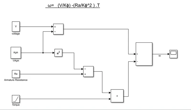
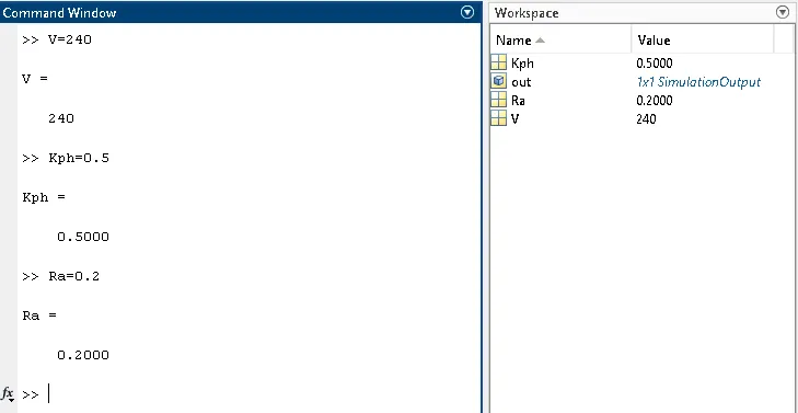
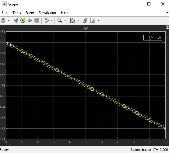
Thus we have plotted the Mathematical model and provided the scope with a speed torque characteristics.
4. Refer to the blog on below topic:
Induction Versus DC brushless motors by Wally Rippel, Tesla
Explain in brief about author’s perspective.
ANSWER:-
- At the beginning of the video the person describes the dominance of internal combustion engines ICE in the world .
- And also discussed the different types of engine used, and said it was totally interest of the user according to their requirement.
- And also presented that Induction motor & brushless dc motor are widely used in coming years .
Dc Brushless Motor:-
- With brushless motor, the rotor includes two or more permanent magnets that generate a dc magnetic field.
- In turn, this magnetic field enters the stator core(made of stacked laminations) and interacts with current flowing within the windings to produce a torque interaction between the roto and stator.
- As the rotor rotates, it is necesary That magnitude and polarity of the stator currents be continuously varied ,and in just the right way , such that the torque remains constant and the conversion of electrical t mechanical energy is optimally efficient.
- The device that provides this current control is called an inverter. Without this Brushless motors are useless motors.
- The author also said that brushless motor produces no starting torque when directly connected to fixed frequency utility power.
Advantages
- Brushless DC motor does not have any carbon brushes, which reduces frequent replacement requirements of brushes and maintenance costs.
- Brushless DC motors have better performance and efficiency as compared to the brushed DC motors due to the involvement of electronic control enabling high-level control over the speed and position of the motor. Brushless DC motor lifespan is approximately 6 times higher than the counter brushed DC motor.
- Brushes can cause high sparks which may result in short life or complete burnout of brushed DC motor. However, in the case of brushless DC motor, due to no spark issue, there are fewer chances of burnout due to sparking issues.
Disadvantages:-
- The cost of a brushless DC motor is comparatively higher as compared to brushed DC motor and the electronic controller also increases the cost of overall setup, as in a traditional motor, low-cost mechanical commutation setup involving brushes is used.
- When brushless DC motor is operated at low speed, slight vibrations occur during low-speed rotation. However, vibrations reduce at high speed.
- Brushed DC motors are easy to operate having simple wiring as the positive terminal is connected to positive and negative terminal is connected to negative wire and motor starts to rotate. However, in the case of brushless DC motor, wiring and operation of the motor are not that simple due to the involvement of electronic control and its link to all the electromagnets.
Induction motors:-
- It is simple, from the name itself we can understand that here, the induction process is involved. When we give the supply to the stator winding, a magnetic flux gets produced in the stator due to the flow of current in the coil.
- The rotor winding is so arranged that each coil becomes short-circuited.
- The flux from the stator cuts the short-circuited coil in the rotor. As the rotor coils are short-circuited, according to Faradays law of electro magnetic induction, the current will start flowing through the coil of the rotor.
- When the current through the rotor coils flows, another flux gets generated in the rotor.
- When a 3 phase induction motor is connected to utility type 3 phase power , torque is produced at the outset.
- The fact that induction motors are directly compatible with conventional utility power is the reason for their success.
Advantages
- The most important advantage of an induction motor is that its construction is quite simple in nature. The construction of the Stator is similar in both Synchronous motors as well as induction motors. However, a slip ring is required to feed DC Supply to the Rotor in the case of a Synchronous Generator.
- These Slip rings are not required in a Squirrel cage induction motor because the windings are permanently short circuited. When compared with a DC Motor the induction motor does not have Brushes and hence, maintenance required is quite low. This leads to a simple construction.
- The working of the motor is independent of the environmental condition. This is because the induction motor is Robust and mechanically strong.
- A Squirrel cage induction motor does not contain Brushes, Slip rings and Commutators. Due to this reason, the cost of the motor is quite low. However, Slip Rings are used in Wound type induction motor to add external resistance to the rotor winding.
- Due to the absence of Brushes, there are no sparks in the motor. It can also be operated in hazardous conditions.
Disadvantages:-
- A single phase induction motor unlike a 3 phase induction motor, does not have a self starting torque. Auxiliaries are required to start a single phase motor.
- During light load conditions, the power factor of the motor drops to a very low value. This is because during the start, the motor draws a large magnetising current to overcome the reluctance offered by the air gap between the Stator and the Rotor.
- Also, the induction motor will take very lesscurrent from the supply main. The vector sum of Load current and Magnetising current lags the voltage by around 75-80 degrees and hence, the power factor is low. Due to high magnetising current, the copper losses of the motor increase. This in turn leads to decrease in the efficiency of the motor.
- speed control of induction motor is very difficult to attain. This is because a 3 phase induction motor is a constant speed motor and for the entire loading range, the change in speed of the motor is very low.
- Induction motors have high input surge currents, which are referred to as Magnetising inrush current. This causes a reduction in voltage at the time of starting the motor.
- Due to poor starting torque, the motor cannot be used for applications which require high starting torque.