Week-6 Challenge: EV Drivetrain
1.Which types of power converter circuits are employed in electric and hybrid electric vehicle?
ANSWER:
Electric Vehicles:
An electric vehicle (EV) is a vehicle that uses one or more electric motors or traction motors for propulsion. An electric
vehicle may be powered through a collector system by electricity from off-vehicle sources, or may be self-contained
with a battery, solar panels, fuel cells or an electric generator to convert fuel to electricity.
Hybrid Electric Vehicles:
A hybrid electric vehicle (HEV) is a type of hybrid vehicles that combines a conventional internal combustion engine
(ICE) system with an electric propulsion system. The presence of the electric powertrain is intended to achieve either
better fuel economy than a conventional vehicle or better performance. There is a variety of HEV types and the
degree to which each function as an electric vehicle (EV) also varies. The most common form of HEV is the hybrid
electric car, although hybrid electric trucks (pickups and tractors), buses, boats and aircraft also exist.
Power converters circuits for electric and hybrid electric vehicles:
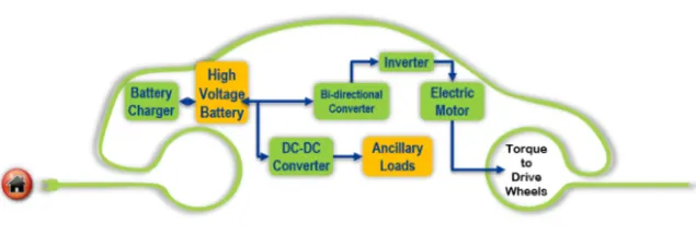
1. Battery pack - this is made up of multiple lithium ion cells and stores the energy required to run the vehicle and provide direct current (DC) output.
2. DC - DC Converter - A battery pack delivers fixed voltage; but the requirement of the different auxiliaries in the EV would vary. The DC -DC converter helps to step down and distribute power to different systems.
3. Battery Management System - BMS continuously monitors the state of the battery and is responsible for cell balancing to deliver max. efficiency from the battery pack.
4. ON - Board Charger - it converts AC received from port to DC to charge back the battery pack.
5. DC - AC Converter - the DC supplied by the battery pack is converted to AC to energize electric motor. This power transfer is managed effectively by a motor.
6. Controller - it controls the frequency of the voltage with the help of power electronic modules which in turn controls the magnitude of the voltage in order to manage the speed of the motor as per the acceleration of the vehicle.
7. Electric motor - this is the prime of an EV unit which converts electrical energy to mechanical energy and delivers to the wheels via direct transmission or single ratio transmission. This motor can act in regeneration modes.
8. CAN module - this carries communication between the control unit and the vehicle and motor.
POWER CONVERTERS IN HEV:
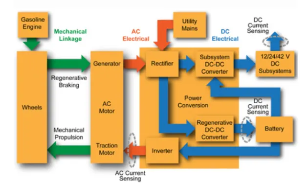
There is no specific diffrence between the converters used in EV and HEV if purpose is taken as a context .Power conversion flow schematic of HEV shown below gives us the idea about the placement of power conversionsdevices in the HEV powertrain system.As you can see instead of bi-directional converter a seperate regenerative DC-DC chopper is used to convert themechanical energy from gasoline engine to alternator(generator) to store energy.
Power electronics is the application of solid state electronics to the control and conversion of electric power. In modern systems, the conversion is performed with semiconductor switching devices such as the power MOSFET & IGBT. In contrast the electronic systems concerned with transmission and processing of signals and data, in power electronics substantial amounts of electrical energy is processed.
The power range is typically from tens of watts to several hundred watts. In industry a common application is the Variable Speed Drive that is used to control the induction motor. The power range of VSDs start from hundred watts and end at tens of megawatts. Switching Technique is adopted from power electronics to control voltage and current for electric motor for electric motor. This avoids high volume of losses by replacing resistor with power switch and these motor modules are operated with high frequency where the Rated Battery Voltage (Vbat) can be reduced to desired voltage by ON - OFF of Modules.
Switching frequency will be in such a way that it utilises Vbat and high & low switches to maintain average desired voltage.
The principle behind power modules isn't controlling the magnitude of the voltage but the duration of high and low value of a voltage resulting the desired voltage level. & this ON - OFF frequency is termed as Duty - Ratio.
Duty Ratio (D) = (ON time)/ (ON + OFF) time. By changing the duty ratio of the power modules, we can vary the voltage from one level to another level. Vavg. = Vbat* D.
According to the respective functions performed, power electronic converters are categorized in the following types
AC to DC - Rectifier, it converts AC to unipolar (DC) Current.
DC to AC - Inverter, it converts DC to AC of desired frequency and voltage.
DC to DC - Chopper, it converts constant to variable DC or variable DC to constant DC.
AC to AC - Cycloconverter, Matrix converter - it converts AC of desired frequency or desired voltage magnitude from AC supply.
AC supply.
These power electronic converters may be found in wide variety of applications such as switch mode power supplies
(SMPS), Electric Machine control, Energy storage systems, Lightning drives, Power generation & distribution, Active power filters, Renewable energy conversion, flexible energy transmission let us go in detail about each converter -
power filters, Renewable energy conversion, flexible energy transmission let us go in detail about each converter -
AC to DC converters I Rectifiers -
These converts AC supply from main lines to DC supply or the load.
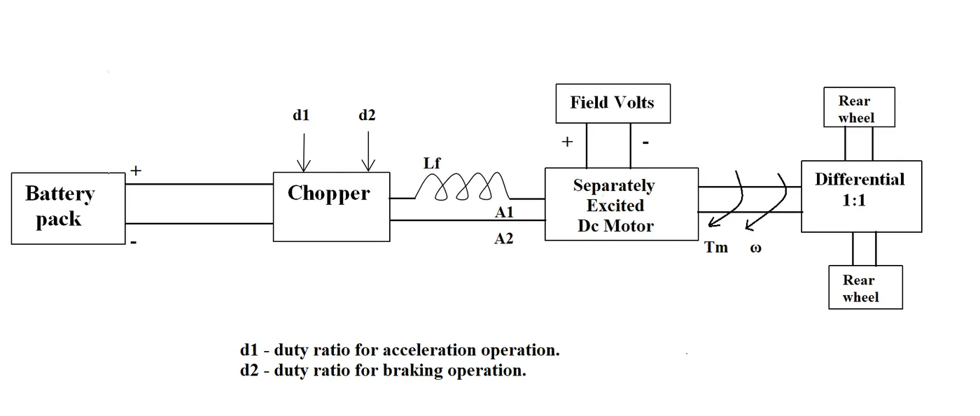
2.An Electric Vehicle's powertrain with 72V battery pack in shown in the diagram below. The duty ratio for acceleration operation is 'd1' and for the braking operation the duty ratio is 'd2'.
The other parameters of the electric vehicle is given below,
Motor and Controller Parameters:
Rated Armature voltage= 72 V
Rated armature current= 400 A
Ra= 0.5Ω, KΦ= 0.7 Volt second
Chopper Switching frequency= 400 Hz
The vehicle speed-torque characteristics are given by the below equation
 ------equation(1)
What is EV steady state speed if duty cycle is 70%?
ANSWER:
Duty cycle=70%=0.7,
Actual voltage=0.7*72= 50.4V
We have torque equation for motor,
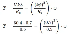
T = 70.56 — 0.98w------- equation(2)
solving equation (1)&(2),
comparing both torque of vehicle and torque of motor,
24.7 ± (0.0051) • w^2 = 70.56 — (0.98) • w
(0.0051w^2) + 0.98w — 45.86 = 0
by solving this by quadratic equation we get,
we get two wvalues as

So, the EV steady state speed if duty cycle is 70% = 38.915 rad/sec or 371 RPM
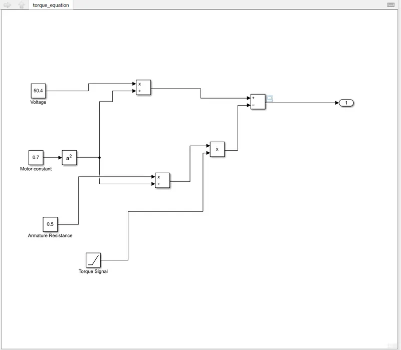
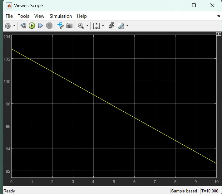
3.Develop a mathematical model of a DC Motor for the below equation using Simulink.
Answer:
For modeling a mathematical model of a DC motor with the given equation, we have to assume values of
some parameters. Also, the above equation is a linear type equation, and hence, we will use a ramp type function for
the Torque. This will ensure a linear function for capturing the behavior of the speed. The values for the constant
terms are considered according to the previous question.
https://drive.google.com/file/d/1wweBxoiuY4-iyqIACKGfvQBwZRS2xVE5/view?usp=sharing
4.
Refer to the blog on below topic:
Induction Versus DC brushless motors by Wally Rippel, Tesla
Explain in brief about author’s perspective.
ANSWER:
The article was written by Wally Rippel who used to work with Tesla Motors and was also a part of creating the
GM EV1. The following points can be concluded to briefly explain his perspective:
i. Mr. Wally Rippel starts with the description of the current scenario of the Internal Combustion Engines (ICE) in
the world of the automobile industry and how there is no such engine that has been deemed ideal. He explains
that the engines were subject to the user requirements. Every requirement has different outcomes for engines.
He co-relates this situation with electric motor drives as well explaining how BLDC and Induction motors are
going to be the future of electric mobility.
ii. He further explains the working of both a 3 phase induction motor and a brushless DC (BLDC) motor. Now the
author has done a comparison between these two technologies and stated some advantages and
disadvantages of each.
iii. The Induction motors carry some advantages like;
- They have no permanent magnets (PM) which have a higher cost.
- The motors have the ability to start under load.
- No inverter is needed.
- Better suited for higher performance characteristics.
iv. The disadvantages induction motors have;
- They cannot operate under a DC source and an AC source is a must.
- Shaft speed is proportionate to line frequency, and hence, when used with utility power, they are constant
speed machines.
- When operated under utility power, they have limited starting torque and somewhat limited running peak
torque capabilities, when compared to DC-type machines.
v. The advantages of BLDC motors:
- Much less rotor heat is generated with the BLDC type of motor drives.
- The peak point energy efficiency for DC brushless motors will typically be a few percentage points higher than
the induction motors.
vi. The disadvantages BLDC motors have;
- As motor size grows, the magnetic losses increase proportionately and the part load efficiency drops.
- Permanent magnets are expensive and difficult to handle due to very large forces that come into play when
anything ferromagnetic gets close to them.
vii. Finally, the author concludes that there are equal advantages and disadvantages for both of the drives and
proves his first hypothesis right about "One size does not fit all". He makes it clear that the BLDC drives will likely
continue to dominate the hybrid and upcoming plug-in hybrid vehicle markets, and the induction drives will
likely maintain dominance for the high-performance pure electric vehicles.