Week-6 Challenge: EV Drivetrain
1. Which types of power converter circuits are employed in electric and hybrid electric vehicle?
ANS:- Power Converter
Power converter is converting electrical energy from one form to another such as converting between AC & DC or changing the voltage & frequency.
Following power converter are used in regular basis:-
1) DC to DC
Chopper - Its convert variable DC to constant DC or constant DC to variable DC.in electrical engginering a DC-DC converter is a catagory of power converter.an electrical circuit which convert a source of direct current (DC) from one voltage level to another by storing the input energy temporary and then realising that energy to output at different voltages.The storage may be either magnetic field storage component(inductor,transformer) or electric field storage component(capacitors).we can control or varry a constant DC voltage with the help of chopper.
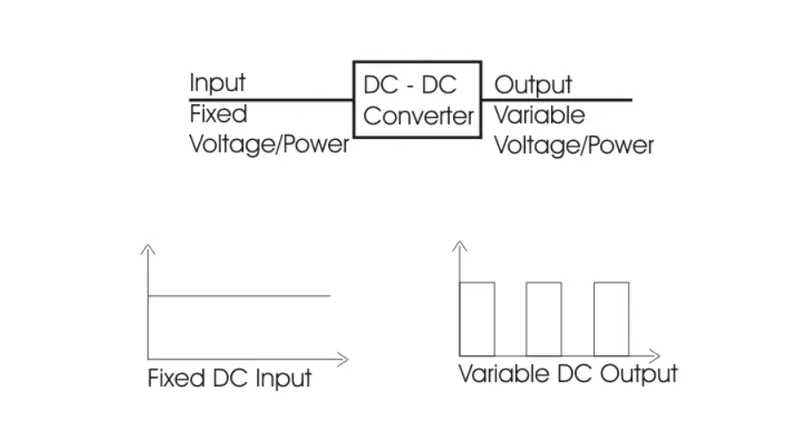
Choppers are of two types:-
1) Step down chopper
2) Step up Chopper
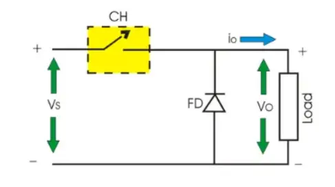
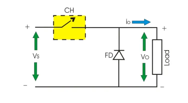
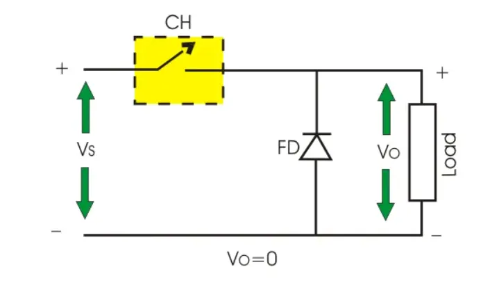
- Step down chopper:- The output voltage is less than the input voltage. the step down chopper as Buck converted is used to reduced the input voltage level at the output side.circuit diagram of step down chopper as shown in below fig.
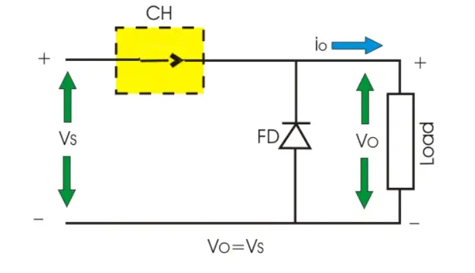
When switch is turned ON Vs is directly appear across the load Vs=Vo as shown in below fig.
When switch is turned off then Vs is disconnected from load Vo=0 as shown in below fig.
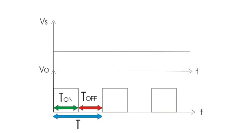
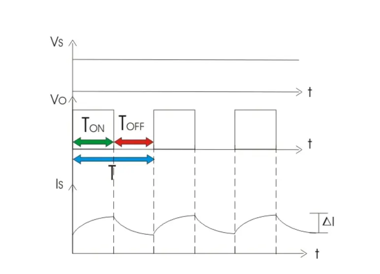
The voltage waveform of step down chopper as shown in below fig.
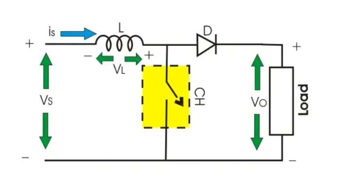
- Step up chopper:- The step up chopper or boost converter is used to increase the inputv voltage level of output side.Step up chopper as shown in below fig.
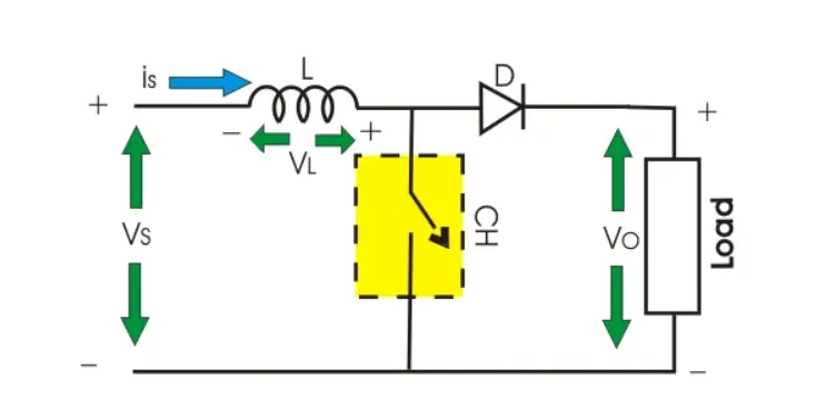
when the switch is ON it short circuit the load.hence output voltage during Ton is zeroduring that period inductor get charged.(Vs=VL).as shown below fig.
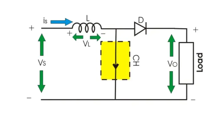
when switch is turned off inductor discharge through the load so we will get summation of both source voltage Vs and inductor voltage VL as a ootput voltage.as shown below fig.
The voltage waveform of step up chopper as shown in below fig.
In car their are many application like radio,lighting system,AC, sensor,vipers etc. it required regulated DC supply & this supply given by this chopper.The battery has a fixed DC supply it is converted into a regulated DC supply by using chopper.
2) AC to AC converter
AC to AC converter connect an AC source to AC load by controlling the amount of power supply to the load.this converter convert the AC voltage at one level to other level by varying magnitude as well as frequency of the supply voltage.
following device that convert AC to AC:-
- transformer autotransformer
- volatge converter
- voltage regulator
- cycloconverter
- variable frequency transformer
these are used in different types of applications including uninterrupted power supply,high power AC to AC transmission,renewable energy conversion system.
3) DC to AC converter
An Inverter converts the DC electricity from source such as batteries or fuel cells to AC electricity at any required voltage used in an electric vehicle motor.this can change the speed at which motor rotates by adjusting the frequency of alternating current.
The use of this converters increase of decrease the power or torque of the motor by adjusting amplitude if the signal.it play significant role capturing energy from regenerative braking and feeding it back to the battery.
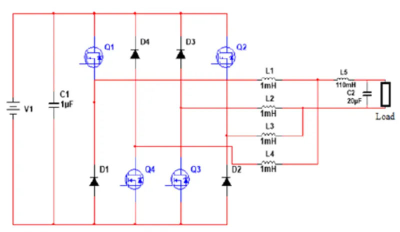
sine wave inverter is a good quality AC power.they used pulse width modulation(PWM) to produces true sine wave.
As we know that our induction motor required AC power supply but we have DC power supply in battery.so we have to convert this DC supply to AC supply to motor.which is done by inverter is convert DC to AC supply as per requirement how much need supply to respected speed.
4) AC to DC convertor
A rectifire is an electrical device that convert AC to DC which flow in only one direction.
Their are mainly two type of rectifire:-
- Uncontrolled rectifire
- Controlled rectifire
Usually the type of rectifires are classified based on their output:-4
- single phase rectifire
- three phase rectifire
- controlled rectifire
- uncontrolled rectifire
- full wave rectifire
- half wave rectifire
- bridge rectifire
- center tapped rectifire
The commonly used rectifire is a bridge rectifire:-
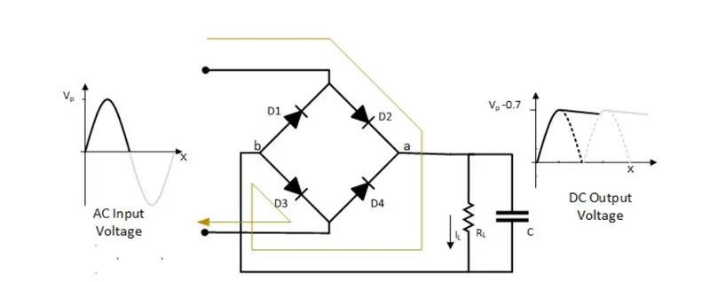
As we know our charge is stored in DC form in the battery.for this battery charging we need DC supply,but the generated power supply & external supply is AC and battery need DC supply. so for this conversion we need rectifire which convert AC to DC.
it comprises a diode and/or thyristor based on the type of rectifire.the output of the rectifire is a pulse DC and hense it is filter using a filter cuicuit.which is usually made a chock/capacitor.charger are the best example of AC to DC converter.
2. An Electric Vehicle's powertrain with 72V battery pack in shown in the diagram below. The duty ratio for acceleration operation is 'd1' and for the braking operation the duty ratio is 'd2'.
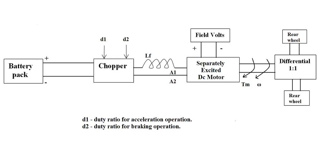
The other parameters of the electric vehicle is given below,
Motor and Controller Parameters:
Rated Armature voltage= 72 V
Rated armature current= 400 A
Ra= 0.5Ω, KΦ= 0.7 Volt second
Chopper Switching frequency= 400 Hz
The vehicle speed-torque characteristics are given by the below equation

What is EV steady state speed if duty cycle is 70%?
ANS:-
We have,
Va=72v
Ia=400A
Ra=0.5ohm
kphi=0.7V-sec
f=400Hz
The speed Vs Torque characteristics of 100% duty cycle is given as,
Tv=24.7+0.051w^2...................(1)
The relation between input/output voltage & the duty cycle is,
Vout=D*Vinput
so, Vout=70%duty cycle*72
= 0.7*72
=50.4V
For a DC motor torque produced is given by.
T=((v*k)/R-((k^2/R)*w))
=((50.4*0.7)/0.5-((0.7^2/0.5)*w
T= 70.56-0.98w.............................(2)
In steady state condition motor torque is equal to load torque,
so, by equating 1 & 2 equation we get,
0.0051w^2+0.98w-45.86........................(3)
Solving the quadratic equation,
w = 38.9rad/sec
Result:- The EV steady state speed is 38.9rad/sec when the duty cycle is 70%.
3. Develop a mathematical model of a DC Motor for the below equation using Simulink.
ω= V/Kϕ -Ra/Kϕ^2 .T
ANS:-
here i have assume constant values,
v=72
k=0.7
Ra=0.5
Above this all are constant but torque,speed is not a constant its a variable so, i have used ramp block as a torque. The model shown below,
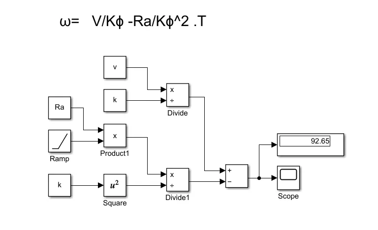
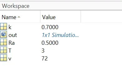
here i have defined constant values in the workspace,as shown below,
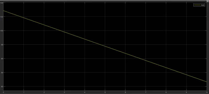
The output graph as shown below,
4. Refer to the blog on below topic:
Induction Versus DC brushless motors by Wally Rippel, Tesla
Explain in brief about author’s perspective.
ANS:-
About author:-
wally ripple is a long time proponent of an electric vehicles.prior to joining Tesla Motor ,he was an engineer at aerovironment ,where he helped develop the EV1 for General Motor and was featured in the documentry movie who killed the electric car?wally has also worked for the jet-propolsion on electric vehicle battery battery research ,among other project.In 1968 as a caltech undergraduate student he build a electric car (a converted 1958 volkswagen microbus) and won the great transcontinental electric car race against MIT.
In this blog authors perspective is:-
- They compaire old and today's technology like a battery,drive machine like motors.he wants to get know it will get stable this technology anywhere.
- They want to know that which motor is better for electric vehicle BLDC or an INDUCTION MOTOR.
- So they compaire are this two technologies.how do they work? what differentiates them?and what do they have in common?
- firstly he goes to BLDC motor,explained the working pronciple.
- then he moves on to Induction motor drives.3-phase motor invented by Nikola Tesla.sometime before 1889.curiosly ,the stator of 3phase insuction motor and DC brushless motor are virtually identical.both have 3 sets of distributed winding that are inserted within the stator core.The essential difference between the two machines is with the rotor.
- After that he informed the induction motor working principle,advantage,limitation,etc.
- In induction motor their are two main parts stator and rotor. stator is a stationary part rotor is a rotating part.when 3phase/1phase supply is given to the stator winding rotating magnetic field produce,then according to faradays law of the electromagnetic induction magnetic field produce in rotor also.(when current carrying conductor placed in magnetic field which experiances force) EMF produce in rotor and motor will run.
- he's main motto which one is better for electric vehicle.
- But as per the application both motor are suitable for car for more torque BLDC motor preferable and for constant speed induction motor is suitable.
- So when their is a need for hybrid performance ,we could see a completely new combination of drive with this two drives.
- So their is no winner in the future of EV & HEV for drives. their can always be new design and combinatins.