Week-6 Challenge: EV Drivetrain
1. Which types of power converter circuits are employed in electric and hybrid electric vehicle?
-Power converters do not only play a very important role but are the back-bone in EV and HEV as they make it possible to run electric motors at different speed with very low energy los. power conversion is the process of converting electrical energy from one form to another or converting one frequency of alternatingcurrent into another. A power converter is an electrical or electro-mechanical device for converting electrical energy. A power converter can convert alternating current (AC) into direct current (DC) and vice versa, change the voltage or frequency of the current or do some combination of these.
-There inlove.
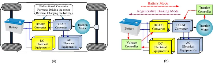
1.1) DC Power converters
1.1.1) DC to DC
1.1.2) DC to AC
1.2) AC Power converters
1.2.1) AC to AC
1.2.2) AC to DC
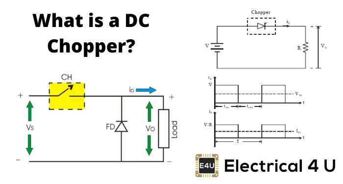
1.1.1) DC to DC (Chopper) : A DC-to-DC converter is an electric circuit or electromechanical device that converts a source of directcurrent (DC) from one voltage level to another. Power levels range from very low (small batteries) to very high (high-voltage power transmission). Examples of such applications are subway cars, trolley buses, EV etc. We can control and vary a constant DC voltage with the help of a chopper.
Chopper is a basically static power electronics device which converts fixed DC voltage/power to variable DC voltage or power. It is nothing but a high speed switch which connects and disconnects the load from source at a high rate to get variable or chopped voltage at the output. It can be used to iether Step up or Step down the Voltage Power
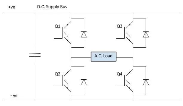
1.1.2) DC to AC (Inverter) : 3 Phase electric motors are the most commonly used in EV nad HEV, they requier AC supply to run at thier desirable speeds but however thier Battery stores power in DC. A DC to AC inverter converts and increases the DC electricity from a source (such as a battery) to AC electricity before sending it out to power a device. In EV the DC/AC inverter also performs the function of charging the vehicle during regenerative braking. The inverter can change the speed at which the motor rotates by adjusting the frequency of the alternating current.
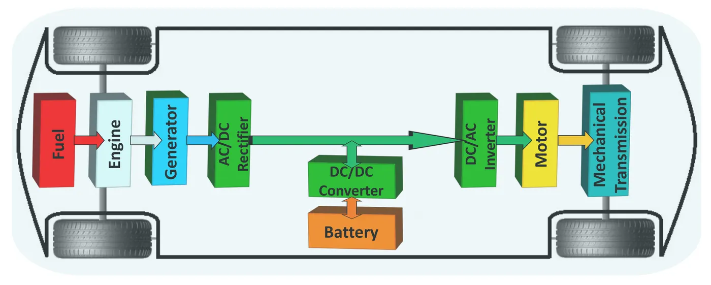
1.2.1) AC to AC : AC to AC converters is used for converting the AC waveforms with one particular frequency and magnitude to AC waveform with another frequency at another magnitude. This conversion is mainly required in case of speed controlling of machines/MOtors, for low frequency and variable voltage magnitude applications as well.
1.2.2) AC to DC : This type of converter is very useful in converting the power generated during regenerative braking in electric vehicles and hybrid electric vehicles to DC and store them in the battery for future use. The modern AC drive consists of an input rectifier converting AC voltage to DC voltage then stores in DC capacitors. The inverter converts the DC voltage back to AC voltage feeding the AC motor at the desired frequency when needed.
2. An Electric Vehicle's powertrain with 72V battery pack in shown in the diagram below. The duty ratio for acceleration operation is 'd1' and for the braking operation the duty ratio is 'd2'.
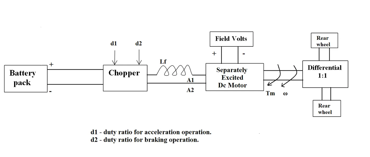
The other parameters of the electric vehicle is given below,
Motor and Controller Parameters:
Rated Armature voltage= 72 V
Rated armature current= 400 A
Ra= 0.5Ω, KΦ= 0.7 Volt second
Chopper Switching frequency= 400 Hz
The vehicle speed-torque characteristics are given by the below equation

What is EV steady state speed if duty cycle is 70%?
Answer :
Torgue calculation (T) = [V*KΦ/Ra]-[w*(KΦ)^2/Ra]
VL = V*d1 = 72*0.7= 50.4V
T=(50.4*0.7/0.5)-(w*(0.7^2)/0.5)
T = 70.56-0.98w
- substituting T in the vehicle speed torgue characteristic equation we have
70.56 - 0.98w = 24.7 + 0.0051w^2
- we obtain a quadratic equation of the form
0.0051w^2 +0.98w - 45.86 = 0
-hence w1 = 38,8 , w2 = -230.9
-since the rotation is in the forward direction w= 38.8 rad/sec
steady speed (w) = 38.8 * 9.54 = 371 rpm
3) Develop a mathematical model of a DC Motor for the below equation using Simulink.
ω= V/Kϕ -Ra/Kϕ^2 .T
-V = voltage
-Kϕ = Motor constant
- T = Torgue
- Ra = Armature resistance
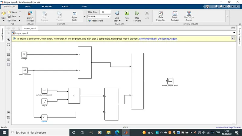
-In the below model block constant blocks have been used for all above constance
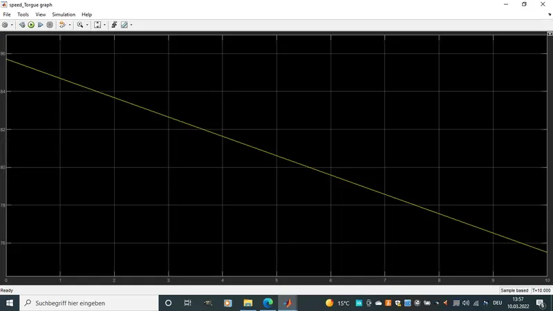
except Torgue. A ramp has been used to show how varrying the torgue value will lid to
change in speed ω.
4) Refer to the blog on below topic:
Induction Versus DC brushless motors by Wally Rippel, Tesla
Explain in brief about author’s perspective.
This block on the engineer Wally Rippel a long time proponent of Electric vehicles, who in his own ways contributed to todays electric vehicles giving his thought own the future of the various electric vehicles driving motors. In a very brief sence Wally Ripple takes the stand that the choise of the motors depends on some factors such as price, power, performance etc hence each motor (DC Brushless and Induction Motors) having its own advantages.
Bruschles Motor/Machine :
The Author gose further to explain how both motors function. Starting with the brushless DC motor This is a motor were DC magnetic field is generated by the rotor which includes two or more permanent magnets t. In turn, this magnetic field enters the stator core (a core made up of thin, stacked laminations) and interacts with currents flowing within the windings to produce a torque interaction between the rotor and stator. As the rotor rotates, it is necessary that the magnitude and polarity of the stator currents be continuously varied by an Inverter(Without it, brushless motors are useless motors.) and in just the right way such that the torque remains constant and the conversion of electrical to mechanical energy is optimally efficient.
3 Phase induction motor :
He then expalin futher more that the 3 phase induction motor was invented by Nikola Tesla sometime before 1889. He then moves on to point the similarity between the stators for the 3-phase induction motor and the DC brushless motor (Both having three sets of “distributed windings” that are inserted within the stator core). The essential difference between the two machines is with the rotor. Unlike the DC brushless rotor, the induction rotor has no magnets – just stacked steel laminations with buried peripheral conductors that form a “shorted structure.” Currents flowing in the stator windings produce a rotating magnetic field that enters the rotor.
The author moves on to point some adavntages and disadvantages over each of the motors as listed below.
Advantages of 3 phase Induction motor:
- The motor has the ability to start under load.
-No inverter is needed.
-The fact that induction motors are directly compatible with conventional utility power is the main reason for their success
-The induction machine when operated with a smart inverter has an advantage over a DC brushless machine magnetic and conduction losses can be traded such that efficiency is optimized since B field is proportional to Voltage and Frequency hence With induction, as machine size grows, losses do not necessarily grow..
Disadvantage of 3 phase Induction motor:
-They cannot operate from DC, AC is a must.
-Shaft speed is proportionate to line frequency. Hence, when used with utility power, they are constant speed machines.
-when operated from utility power, they have limited starting torque and somewhat limited running peak torque capabilities, when compared to DC type machines.
-Induction machines are more difficult to control. The control laws are more complex and difficult to understand. Achieving stability over the entire torque-speed range and over temperature is more difficult with induction than with DC brushless. This means added development costs, but likely little or no recurring costs.
Wally Ripple makes some point on how some of the difficulties faced with induction motors could be overcomed. such as
-Add an inverter (without any feedback control) and it becomes possible to power an induction machine from a battery or other DC source
-variable speed also becomes possible simply by adjusting the inverter frequency. Still, torque performance is low compared with DC machines.
-Add some feedback loops such that the inverter produces the exact frequency that the motor “desires,” and the induction motor is now capable of competing with DC and DC brushless for vehicle applications.
Advantages Brushless DC Motor:
-The DC brushless drive can also operate at unity power factor, whereas the best power factor for the induction drive is about 85 percent.
-The peak point energy efficiency for a DC brushless drive is typically a few percentage points higher than for an induction drive.
Disadvantage of Brushless DC motor:
-a brushless DC motor produces no starting torque when directly connected to fixed frequency utility power.
-They really need the aid of an inverter whose “phase” is maintained in step with the angular position of the rotor.
-With DC brushless, as machine size grows, the magnetic losses increase proportionately and part load efficiency drops.
This brings the author to a situation both motors have usful advantages over one another and he points out thies similarities and differences.
Similarities between Brushless and Induction:
-Both DC brushless and induction drives use motors having similar stators
Differences between Brushless and Induction:
-The only differences are The rotors and the inverter controls.
Conclusion
In his conlusion no motor winns over the other but are respectively used in different condtions. DC Brushless remains the best obtion for HEV and EV with just average performance while Induction motors are best suitables for pure EV with great performance