Week-6 Challenge: EV Drivetrain
1. Which types of power converter circuits are employed in electric and hybrid electric vehicle?
Answer:
Hybrid Electric Vehicles
Today's hybrid electric vehicles (HEVs) are powered by an internal combustion engine in combination with one or more electric motors that use energy stored in batteries. HEVs combine the benefits of high fuel economy and low tailpipe emissions with the power and range of conventional vehicles.
A wide variety of HEV models are currently available. Although HEVs are often more expensive than similar conventional vehicles, some cost may be recovered through fuel savings or state incentives. Compare HEV and non-hybrid models side by side using the "Can a Hybrid Save Me Money?" tool on FuelEconomy.gov. The tool compares the costs of a selected HEV with a comparably equipped non-hybrid model from the same manufacturer and provides fuel cost savings associated with the HEV option.
Help from an Electric Motor
In an HEV, the extra power provided by the electric motor may allow for a smaller combustion engine. The battery can also power auxiliary loads and reduce engine idling when the vehicle is stopped. Together, these features result in better fuel economy without sacrificing performance.
Regenerative Braking
An HEV cannot plug in to off-board sources of electricity to charge the battery. Instead, the vehicle uses regenerative braking and the internal combustion engine to charge. The vehicle captures energy normally lost during braking by using the electric motor as a generator and storing the captured energy in the battery.
View an animation showing how HEVs work. Download Flash Player or view the text version.
Fuel-Efficient System Design
HEVs can be either mild or full hybrids, and full hybrids can be designed in series or parallel configurations.
-
Mild hybrids—also called micro hybrids—use a battery and electric motor to help power the vehicle and can allow the engine to shut off when the vehicle stops (such as at traffic lights or in stop-and-go traffic), further improving fuel economy. Mild hybrid systems cannot power the vehicle using electricity alone. These vehicles generally cost less than full hybrids but provide less fuel economy benefit than full hybrids.
-
Full hybrids have larger batteries and more powerful electric motors, which can power the vehicle for short distances and at low speeds. These vehicles cost more than mild hybrids but provide better fuel economy benefits.
There are different ways to combine the power from the electric motor and the engine. Parallel hybrids—the most common HEV design—connect the engine and the electric motor to the wheels through mechanical coupling. Both the electric motor and the internal combustion engine drive the wheels directly. Series hybrids, which use only the electric motor to drive the wheels, are more commonly found in plug-in hybrid electric vehicles.
TYPES OF POWER CONVERTER CIRCUITS:
CHOPPER:
Chopper circuits are known as DC to DC converters. Similar to the transformers of the AC circuit, choppers are used to step up and step down the DC power. They change the fixed DC power to variable DC power. Using these, DC power supplied to the devices can be adjusted to the required amount.
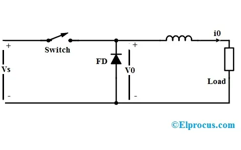
The principle of operation of chopper can be understood from the circuit diagram below. The circuit consists of a semiconductor diode, resistor, and a load. For all type of chopper circuit, the output voltage value is controlled by periodic closing and opening of the switches used in the circuit.
The chopper can be viewed as an ON/OFF switch that can rapidly connect or disconnect the source to load connection. Continuous DC is given as source to the chopper as Vs and chopped DC is obtained across the load as V0.
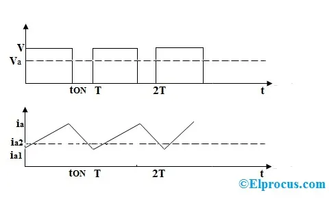
Output Voltage and Current Waveforms
Above are the output voltage and current waveforms of a chopper circuit. From the voltage waveform, it can be seen that during the period of TON the load voltage V0 is equal to the source voltage Vs. But when the interval TOFF occurs, the DC voltage step downs to zero, thus making the load short-circuited.
RECTIFIER:
rectifier is an electrical device that converts alternating current (AC), which periodically reverses direction, to direct current (DC), which flows in only one direction. The reverse operation is performed by the inverter.
The process is known as rectification, since it "straightens" the direction of current. Physically, rectifiers take a number of forms, including vacuum tube diodes, wet chemical cells, mercury-arc valves, stacks of copper and selenium oxide plates, semiconductor diodes, silicon-controlled rectifiers and other silicon-based semiconductor switches. Historically, even synchronous electromechanical switches and motor-generator sets have been used. Early radio receivers, called crystal radios, used a "cat's whisker" of fine wire pressing on a crystal of galena (lead sulfide) to serve as a point-contact rectifier or "crystal detector".
Rectifiers have many uses, but are often found serving as components of DC power supplies and high-voltage direct current power transmission systems. Rectification may serve in roles other than to generate direct current for use as a source of power. As noted, detectors of radio signals serve as rectifiers. In gas heating systems flame rectification is used to detect presence of a flame.
Depending on the type of alternating current supply and the arrangement of the rectifier circuit, the output voltage may require additional smoothing to produce a uniform steady voltage. Many applications of rectifiers, such as power supplies for radio, television and computer equipment, require a steady constant DC voltage (as would be produced by a battery). In these applications the output of the rectifier is smoothed by an electronic filter, which may be a capacitor, choke, or set of capacitors, chokes and resistors, possibly followed by a voltage regulator to produce a steady voltage.
Half-wave rectification[edit]
In half-wave rectification of a single-phase supply, either the positive or negative half of the AC wave is passed, while the other half is blocked. Because only one half of the input waveform reaches the output, mean voltage is lower. Half-wave rectification requires a single diode in a single-phase supply, or three in a three-phase supply. Rectifiers yield a unidirectional but pulsating direct current; half-wave rectifiers produce far more ripple than full-wave rectifiers, and much more filtering is needed to eliminate harmonics of the AC frequency from the output.
The no-load output DC voltage of an ideal half-wave rectifier for a sinusoidal input voltage is:[2]
- {\displaystyle {\begin{aligned}V_{\mathrm {rms} }&={\frac {V_{\mathrm {peak} }}{2}}\\[8pt]V_{\mathrm {dc} }&={\frac {V_{\mathrm {peak} }}{\pi }}\end{aligned}}}

where:
- Vdc, Vav – the DC or average output voltage,
- Vpeak, the peak value of the phase input voltages,
- Vrms, the root mean square (RMS) value of output voltage.
Full-wave rectification[edit]
A full-wave rectifier converts the whole of the input waveform to one of constant polarity (positive or negative) at its output. Mathematically, this corresponds to the absolute value function. Full-wave rectification converts both polarities of the input waveform to pulsating DC (direct current), and yields a higher average output voltage. Two diodes and a center tapped transformer, or four diodes in a bridge configuration and any AC source (including a transformer without center tap), are needed.[3] Single semiconductor diodes, double diodes with a common cathode or common anode, and four- or six-diode bridges are manufactured as single components.
For single-phase AC, if the transformer is center-tapped, then two diodes back-to-back (cathode-to-cathode or anode-to-anode, depending on output polarity required) can form a full-wave rectifier. Twice as many turns are required on the transformer secondary to obtain the same output voltage than for a bridge rectifier, but the power rating is unchanged.
The average and RMS no-load output voltages of an ideal single-phase full-wave rectifier are:
- {\displaystyle {\begin{aligned}V_{\mathrm {dc} }=V_{\mathrm {av} }&={\frac {2\cdot V_{\mathrm {peak} }}{\pi }}\\[8pt]V_{\mathrm {rms} }&={\frac {V_{\mathrm {peak} }}{\sqrt {2}}}\end{aligned}}}

Very common double-diode rectifier vacuum tubes contained a single common cathode and two anodes inside a single envelope, achieving full-wave rectification with positive output. The 5U4 and the 80/5Y3 (4 pin)/(octal) were popular examples of this configuration.
INVERTER:
An inverter can be defined as it is a compact and rectangular shaped electrical equipment used to convert direct current (DC) voltage to alternating current (AC) voltage in common appliances. The applications of DC involves several small types of equipment like solar power systems. Direct current is used in many of the small electrical equipment such as solar power systems, power batteries, power-sources, fuel cells because these are simply produced direct current.
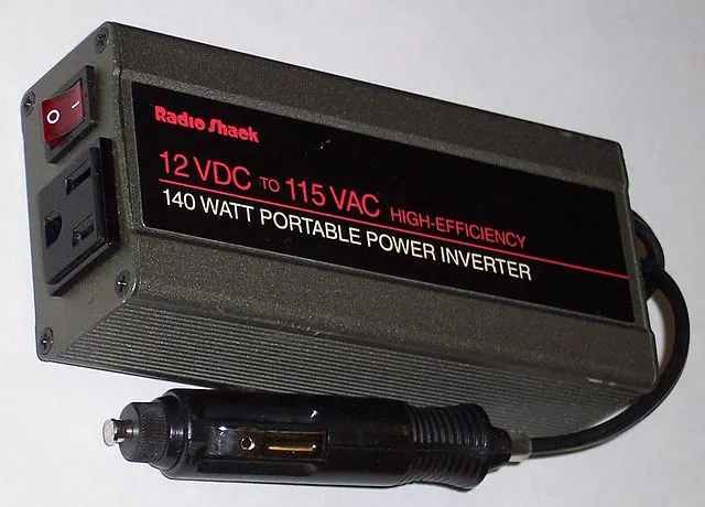
The basic role of an inverter is to change DC power into AC power. The AC power can be supplied to homes, and industries using the public utility otherwise power grid, the alternating-power systems of the batteries can store only DC power. In addition, almost all the household appliances, as well as other electrical equipment can be functioned by depending on AC power.
In some cases, generally, the input voltage is lesser whenever the output voltage is equivalent to the grid supply voltage of either 120 V otherwise 240 V based on the country. These devices are standalone devices for some applications like solar power. There are different types of inverters available in the market based on the switching waveform shape. An inverter uses DC power sources to provide an AC voltage to giving the supply to the electronic as well as electrical equipment
Working of Inverter
The working of an inverter is, it converts DC to AC, and these devices never generate any kind of power because the power is generated by the DC source. In some situations like when the DC voltage is low then we cannot use the low DC voltage in a home appliance. So due to this reason, an inverter can be used whenever we utilize solar power panel.
Types of Inverters
Inverters are classified into two type’s namely single phase and three phases
Single Phase Inverter
Single phase inverters are classified into two types namely half-bridge inverter & full bridge inverter
Half Bridge Inverter
The half-bridge inverter is an essential building block in the full bridge inverter. It can be built with two switches where each one of its capacitors includes an o/p voltage which is equivalent to Vdc2. Additionally, the switches balance each other, if one switch is activated then automatically another switch will deactivate.
Full Bridge Inverter
The full bridge inverter circuit converts direct current to alternate current. It can be achieved by opening as well as closing the switches within the correct series. This type of inverter has dissimilar operating states which depend on closed switches.
Three Phase Inverter
A three-phase inverter is used to alter an input DC to a 3-phase output AC. Generally, its 3-arms are deferred with 120° of an angle to produce a 3-phase AC supply. The inverter control which has a 50% of the ratio as well as controlling can take place after every T/6 of the time T. The switches used in the inverter complement each other.
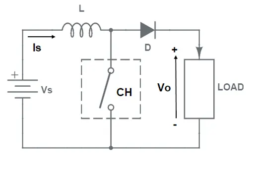
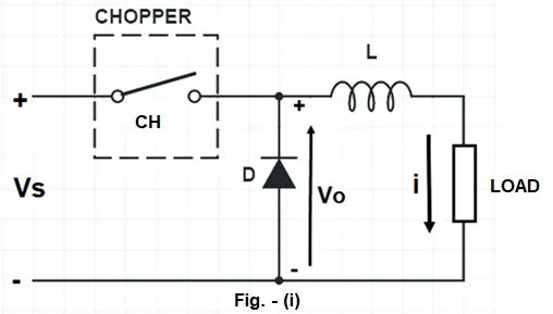
To understand the working principle, let us first have a look at the circuit diagram of step-up chopper. This is shown in figure below. In the circuit diagram, chopper is shown as a switch CH. We will understand the working of this chopper in two steps: Switch ON period and Switch OFF period of chopper.
STEP DOWN CHOPPER:
A Step-down chopper is a static device that step downs its DC input voltage. The value of average output DC voltage of this chopper is less than that of its fixed DC input source voltage. This type of chopper is more common.
Working Principle:
Before we start discussing the working principle of Step-down Chopper, it is imperative to first have a look at its circuit diagram. The circuit diagram is shown in figure below.
2. An Electric Vehicle's powertrain with 72V battery pack in shown in the diagram below. The duty ratio for acceleration operation is 'd1' and for the braking operation the duty ratio is 'd2'.
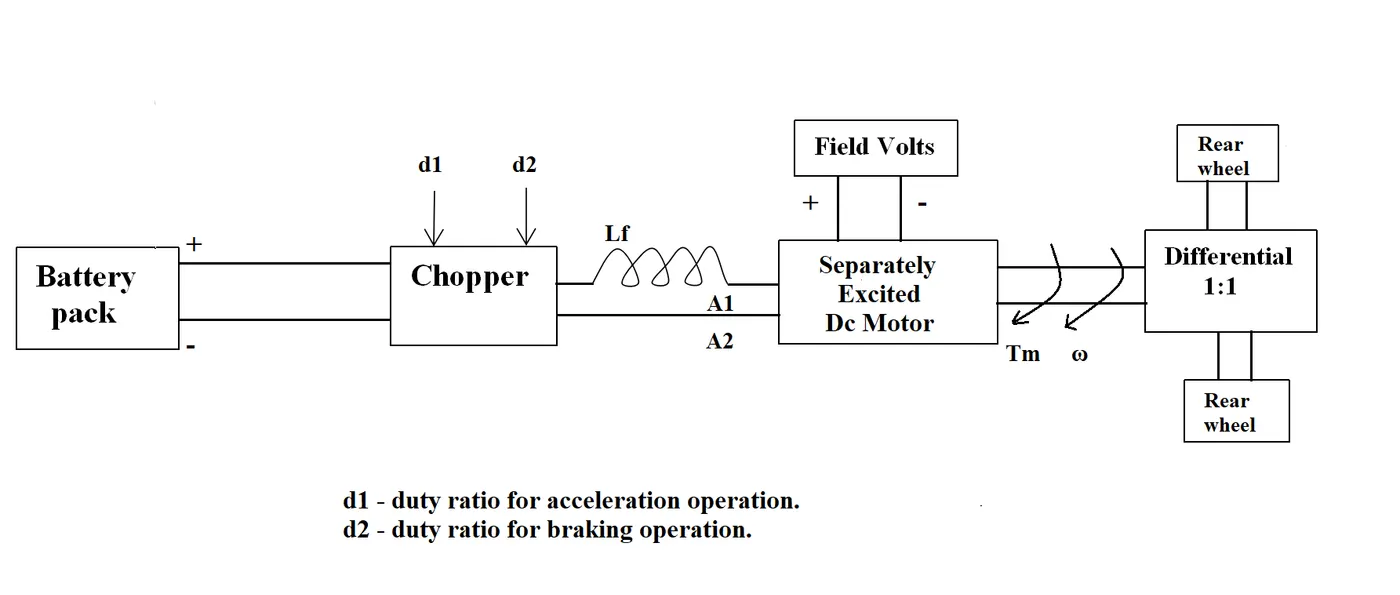
The other parameters of the electric vehicle is given below,
Motor and Controller Parameters:
Rated Armature voltage= 72 V
Rated armature current= 400 A
Ra= 0.5Ω, KΦ= 0.7 Volt second
Chopper Switching frequency= 400 Hz
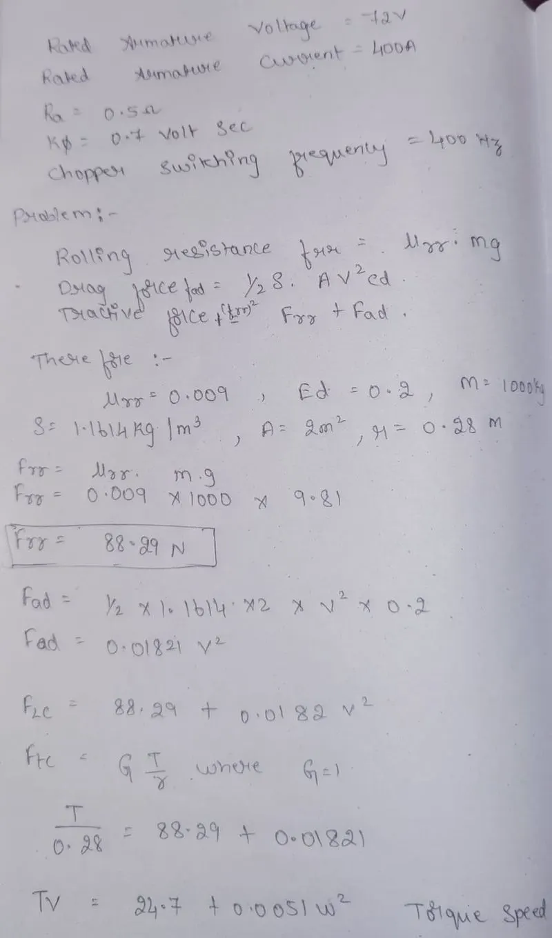
The vehicle speed-torque characteristics are given by the below equation

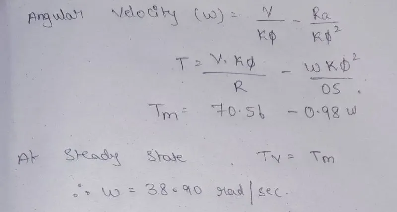
What is EV steady state speed if duty cycle is 70%?
SOLUTION:
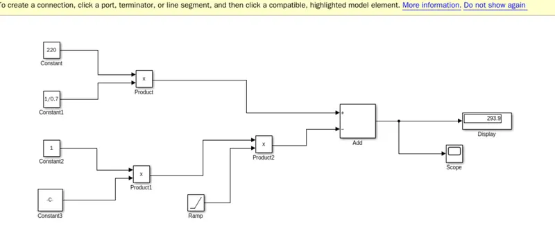
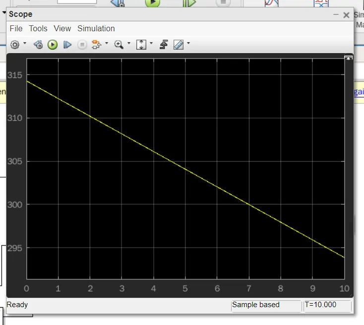
3. Develop a mathematical model of a DC Motor for the below equation using Simulink.
ωω= V/Kϕϕ -Ra/Kϕϕ^2 .T
SOLUTION:
4. Refer to the blog on below topic:
Induction Versus DC brushless motors by Wally Rippel, Tesla
Explain in brief about author’s perspective.
ANSWER:
Wally Rippel is a long-time proponent of electric vehicles. Prior to joining Tesla Motors, he was an engineer at AeroVironment, where he helped develop the EV1 for General Motors and was featured in the documentary movie, Who Killed the Electric Car? Wally has also worked for the Jet Propulsion Laboratory on electric vehicle battery research, among other projects. In 1968, as a Caltech undergraduate student, he built an electric car (a converted 1958 Volkswagen microbus) and won the Great Transcontinental Electric Car Race against MIT
there were lead acid batteries, DC brush motors, and contactor controllers. Today, none of these remain (including my hair). Lead has been replaced by lithium and DC by either DC brushless or induction. Contactors, meanwhile, have given way to modulating inverters. So, will each of these elements also become obsolete in the near future or is it possible that some “stability” may be at hand? Without a good crystal ball, it is hard to predict the future. My guess, however, is that we will see both induction and brushless machines “duke it out” for many years to come. Each will have its loyal proponents and religious detractors.
A Closer Look
So what are these two technologies? How do they work? What differentiates them? And what do they have in common? Let’s start with DC brushless drives.
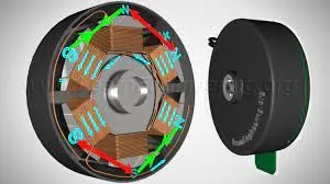
With brushless machines, the rotor includes two or more permanent magnets that generate a DC magnetic field (as seen from the vantage point of the rotor). In turn, this magnetic field enters the stator core (a core made up of thin, stacked laminations) and interacts with currents flowing within the windings to produce a torque interaction between the rotor and stator. As the rotor rotates, it is necessary that the magnitude and polarity of the stator currents be continuously varied – and in just the right way - such that the torque remains constant and the conversion of electrical to mechanical energy is optimally efficient. The device that provides this current control is called an inverter. Without it, brushless motors are useless motors.
Let’s move on to induction motor drives. A forerunner of the 3-phase induction motor was invented by Nikola Tesla sometime before 1889. Curiously, the stators for the 3-phase induction motor and the DC brushless motor are virtually identical. Both have three sets of “distributed windings” that are inserted within the stator core. The essential difference between the two machines is with the rotor.
Unlike the DC brushless rotor, the induction rotor has no magnets – just stacked steel laminations with buried peripheral conductors that form a “shorted structure.” Currents flowing in the stator windings produce a rotating magnetic field that enters the rotor. In turn, the frequency of this magnetic field as “seen” by the rotor is equal to the difference between the applied electrical frequency and the rotational “frequency” of the rotor itself. Accordingly, an induced voltage exists across the shorted structure that is proportionate to this speed difference between the rotor and electrical frequency. In response to this voltage, currents are produced within the rotor conductors that are approximately proportionate to the voltage, hence the speed difference. Finally, these currents interact with the original magnetic field to produce forces – a component of which is the desired rotor torque.
When a 3-phase induction motor is connected to utility type 3-phase power, torque is produced at the outset; the motor has the ability to start under load. No inverter is needed. (Were an inverter needed, Tesla’s invention would have been useless until sometime in the 1960s.) The fact that induction motors are directly compatible with conventional utility power is the main reason for their success. In contrast, a brushless DC motor produces no starting torque when directly connected to fixed frequency utility power. They really need the aid of an inverter whose “phase” is maintained in step with the angular position of the rotor.
While 3-phase induction motors have great utility, they also have some severe limitations. They cannot operate from DC; AC is a must. Shaft speed is proportionate to line frequency. Hence, when used with utility power, they are constant speed machines. Finally, when operated from utility power, they have limited starting torque and somewhat limited running peak torque capabilities, when compared to DC type machines.
Add an inverter (without any feedback control) and it becomes possible to power an induction machine from a battery or other DC source; variable speed also becomes possible simply by adjusting the inverter frequency. Still, torque performance is low compared with DC machines. Add some feedback loops such that the inverter produces the exact frequency that the motor “desires,” and the induction motor is now capable of competing with DC and DC brushless for vehicle applications.
Brushless or Induction?
Back in the 1990s all of the electric vehicles except one were powered by DC brushless drives. Today, all the hybrids are powered by DC brushless drives, with no exceptions. The only notable uses of induction drives have been the General Motors EV-1; the AC Propulsion vehicles, including the tzero; and the Tesla Roadster.
Both DC brushless and induction drives use motors having similar stators. Both drives use 3-phase modulating inverters. The only differences are the rotors and the inverter controls. And with digital controllers, the only control differences are with control code. (DC brushless drives require an absolute position sensor, while induction drives require only a speed sensor; these differences are relatively small.)
One of the main differences is that much less rotor heat is generated with the DC brushless drive. Rotor cooling is easier and peak point efficiency is generally higher for this drive. The DC brushless drive can also operate at unity power factor, whereas the best power factor for the induction drive is about 85 percent. This means that the peak point energy efficiency for a DC brushless drive will typically be a few percentage points higher than for an induction drive.
In an ideal brushless drive, the strength of the magnetic field produced by the permanent magnets would be adjustable. When maximum torque is required, especially at low speeds, the magnetic field strength (B) should be maximum – so that inverter and motor currents are maintained at their lowest possible values. This minimizes the I² R (current² resistance) losses and thereby optimizes efficiency. Likewise, when torque levels are low, the B field should be reduced such that eddy and hysteresis losses due to B are also reduced. Ideally, B should be adjusted such that the sum of the eddy, hysteresis, and I² losses is minimized. Unfortunately, there is no easy way of changing B with permanent magnets.
In contrast, induction machines have no magnets and B fields are “adjustable,” since B is proportionate to V/f (voltage to frequency). This means that at light loads the inverter can reduce voltage such that magnetic losses are reduced and efficiency is maximized. Thus, the induction machine when operated with a smart inverter has an advantage over a DC brushless machine – magnetic and conduction losses can be traded such that efficiency is optimized. This advantage becomes increasingly important as performance is increased. With DC brushless, as machine size grows, the magnetic losses increase proportionately and part load efficiency drops. With induction, as machine size grows, losses do not necessarily grow. Thus, induction drives may be the favored approach where high-performance is desired; peak efficiency will be a little less than with DC brushless, but average efficiency may actually be better.
Permanent magnets are expensive – something like $50 per kilogram. Permanent magnet (PM) rotors are also difficult to handle due to very large forces that come into play when anything ferromagnetic gets close to them. This means that induction motors will likely retain a cost advantage over PM machines. Also, due to the field weakening capabilities of induction machines, inverter ratings and costs appear to be lower, especially for high performance drives. Since spinning induction machines produce little or no voltage when de-excited, they are easier to protect.
I almost forgot: Induction machines are more difficult to control. The control laws are more complex and difficult to understand. Achieving stability over the entire torque-speed range and over temperature is more difficult with induction than with DC brushless. This means added development costs, but likely little or no recurring costs.
My conclusion is that DC brushless drives will likely continue to dominate in the hybrid and coming plug-in hybrid markets, and that induction drives will likely maintain dominance for the high-performance pure electrics. The question is what will happen as hybrids become more electrically intensive and as their performance levels increase? The fact that so much of the hardware is common for both drives could mean that we will see induction and DC brushless live and work side by side during the coming golden era of hybrid and electric vehicles.