Week-6 Challenge: EV Drivetrain
Aim
To study about power converter circuits
GOVERNING EQUATION :
To solve the problem, we have used following formula :
Speed - Torque Equation,
ω = V / (K Phi) - R_a / (K Phi)^2*T_m '
Where,
ω = Speed of the motor
V = Supply Voltage
Kphi = constant = ' E_b/ω '
E_b = Back E.M.F
T_m = Torque of moto
R_a = Armature Resistan
OBJECTIVES :
1. To identify the types of power converter circuits employed in electric and hybrid electric vehicle.
2. To finf the steady state speed of an EV with given inputs if duty cycle is 70%.
1.Power electronic Convertors
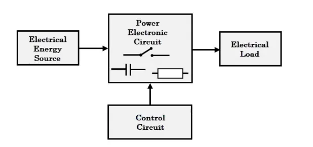
The block diagram of a power electronic converter is shown in figure above. It consist of an electrical energy source, power electronic
circuit, a control circuit and an electric load. This converter changes one form of electrical energy to other form of electrical energy.
The power electronic circuit consists of both power part and control part. Power part transfers the energy from source to load and it
consists of power electronic switches (SCR or TRIAC), transformers, electric choke, capacitors, fuses and sometimes resistors.
The control circuit or block regulates the elements in the power part of the converter. This block is built with a complex low power
electronic circuit that consists of either analog or digital circuit assembly.
Power electronic converters perform various basic power conversion functions. This converter is a single power conversion stage that can
perform any of the functions in AC and DC power conversion systems.
Based on the type of function performed, power electronic converters are categorized into following types :
AC to DC ( Rectifier )
DC to AC ( Inverter )
DC to DC ( Chopper )
AC to AC ( Regulator )
AC to DC ( Rectifier ) :
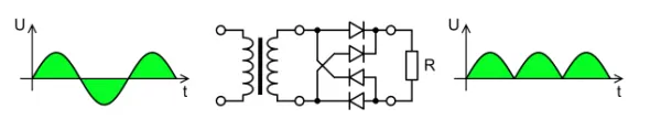
A rectifier is an electrical device that converts alternating current (AC), which periodically reverses direction, to direct current (DC),
which flows in only one direction. The reverse operation is performed by the inverter.
Rectifiers have many uses, but are often found serving as components of DC power supplies and high-voltage direct current power
transmission systems. Rectification may serve in roles other than to generate direct current for use as a source of power. As noted,
detectors of radio signals serve as rectifiers. In gas heating systems flame rectification is used to detect presence of a flame.
DC to AC ( Inverter ) :
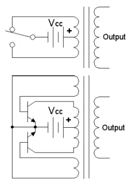
A power inverter, or inverter, is a power electronic device or circuitry that changes direct current (DC) to alternating current (AC). The
resulting AC frequency obtained depends on the particular device employed. Inverters do the opposite of “converters” which were originally
large electromechanical devices converting AC to DC.
The input voltage, output voltage and frequency, and overall power handling depend on the design of the specific device or circuitry. The
inverter does not produce any power; the power is provided by the DC source.
A power inverter can be entirely electronic or may be a combination of mechanical effects (such as a rotary apparatus) and electronic
circuitry. Static inverters do not use moving parts in the conversion process.
DC to DC ( Chopper ) :
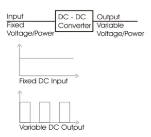
In electronics, a chopper circuit is used to refer to numerous types of electronic switching devices and circuits used in power control and
signal applications. A chopper is a device that converts fixed DC input to a variable DC output voltage directly. Essentially, a chopper is an
electronic switch that is used to interrupt one signal under the control of another.
In power electronics applications, since the switching element is either fully on or fully off, its losses are low and the circuit can provide
high efficiency.
However, the current supplied to the load is discontinuous and may require smoothing or a high switching frequency to avoid undesirable
effects.
AC to AC ( Regulator ) :
A voltage regulator is a system designed to automatically maintain a constant voltage level. A voltage regulator may use a simple feed-
forward design or may include negative feedback. It may use an electromechanical mechanism, or electronic components. Depending on
the design, it may be used to regulate one or more AC or DC voltages.
Electronic voltage regulators are found in devices such as computer power supplies where they stabilize the DC voltages used by the
processor and other elements.
2.To find the steady state if duty cycle is 70%
Given :
Rated Armature voltage = 72 V
Rated armature current = 400 A
Ra = 0.5Ω, KΦ = 0.7 Volt second
Chopper Switching frequency = 400 Hz
Soluton :
Speed-Torque equation of motor,
' ω = V/(K Phi)-R_a/(K Phi)^2*T_m '
For the value of 'V' we need multiply the Armature voltage with duty cycle -
therefore,
' V = 72*(70/100)=50.4 text(Volts) '
By susbstituting the values in Speed -Torque equation of motor we get,
' T_m = 70.56-0.98omega '
We have been given that Vehicle Speed Torque Characteristics as,
' T_v = 24.7+0.0051w^2 '
Where,
' T_v ' = Torque of the Vehicle
At Steady State,
' T_v = T_m '
By substituting the equations we get,
' 24.7+0.0051omega^2 = 70.56-0.98omega '
On solving this Equation we get the vaules of ' ω ' as,
' ω = 32.98, ω = -231.07 '
3. Induction versus DC brushless motor
According to authors perspective, Firstly he gave the description of DC brushless motor about its parts and specifications and
what is called and next description about Induction motor about is component and working of Induction motor. Then he compared the DC
brushless and induction which he metioned that 3- phase induction motor can produce output torque and also have an ability to start under
the load without any inverter,as of DC brushless motor produces nostarting torque when directly connected to fixed frequency utility power
and also inverter is needed to start under load.Then he discussed about the limitations of the 3-Phase induction motor they cannot operate
from DC; AC is a must. Shaft speed is proportionate to line frequency. Hence, when used with utility power, they are constant speed
machines. Finally, when operated from utility power, they have limited starting torque and somewhat limited running peak torque
capabilities, when compared to DC type machines.Inverter can be added to 3-Phase induction so that we can supply power from DC source
or Battery and also we can get variable speeds and can adjust the frequencies.
Then he discussed as the only main difference between DC brushless and Induction motor is of control code and also the rotor of DC
brushless gets less heated at peak torque as that of Induction motor rotor.
Then he discussed about the loses when the motor runs which is the induction machine when operated with a smart
inverter has an advantage over a DC brushless machine – magnetic and conduction losses can be traded such that efficiency
is optimized. This advantage becomes increasingly important as performance is increased.
With DC brushless, as machine size grows, the magnetic losses increase proportionately and part load efficiency drops.
With induction, as machine size grows, losses do not necessarily grow. Thus, induction drives may be the favored approach
where high-performance is desired; peak efficiency will be a little less than with DC brushless, but average efficiency may
actually be better.