Week - 4
1 Implement control logic of a “washing machine” using Stateflow as per given sequence:
Condition
If the power supply is available, the system gets activated
If the Water supply is not available, stop the process & indicate through LED
Soaking time should be 200s followed by Washing time of 100s.
Then rinsing happens for next 20s & dryer runs for 50s
Stateflow:It includes transition diagrams,flow charts,state transition tables.
Control Logic:It is the logic of the model system using state flow.
Given Data:
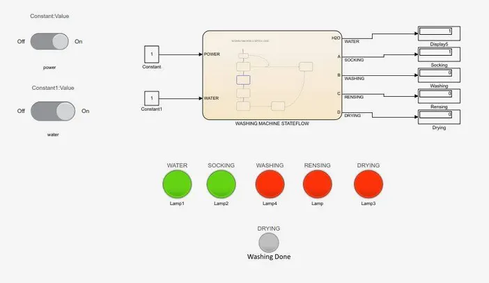
Socking-0 to 200sec
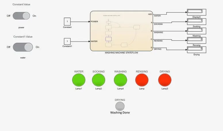
Washing-200 to 300 sec
Rinsing-300 to 320 sec
Drying-320 to 370 sec
Blocks used
Constant,Lamp,Slider Switch,State Flow,Display
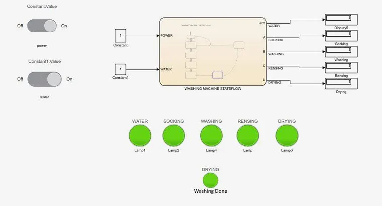
Model
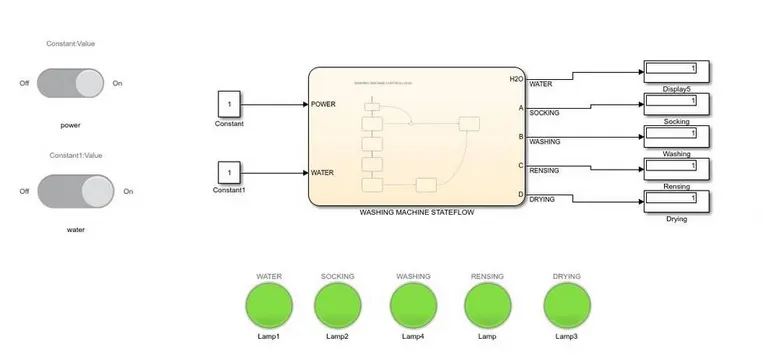
State flow:Washing Machine Control Logic
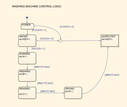
Diffrent States of Model
Socking
Washing
Rinsing
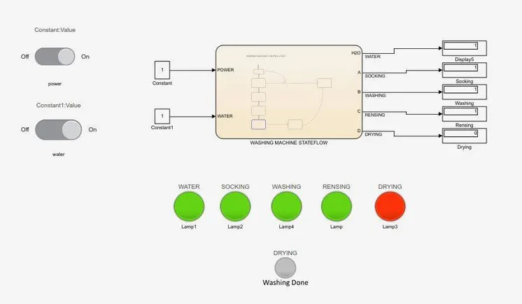
Drying
2.Make a Simulink chart for the “Gear shift” logic as per below conditions:
Given Data
Speed Range(kmph) Gear
0 to 15 - 1
16 to 25 - 2
26 to 40 - 3
41 to 60 - 4
Above 61 - 5
Explanation
When the shifter is pushed for the desired gear the shaft rotates at the speed of the engaged gear.Upshifting is shifting for higher gears
Downshifting means going for lower gears.
Blocks used
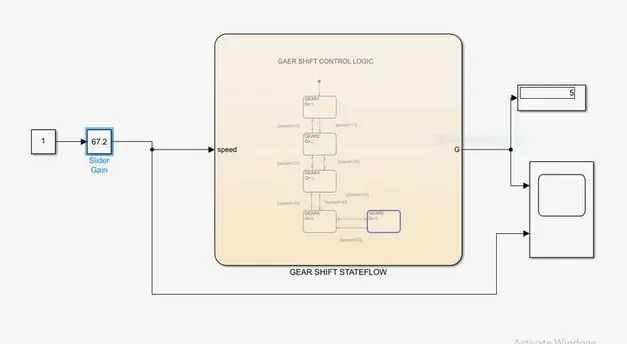
Constant,slider gain,Lamp,Custom Gauge,Scope,State Flow
MODEL
Procedure
At initial state,the slider position is at 0
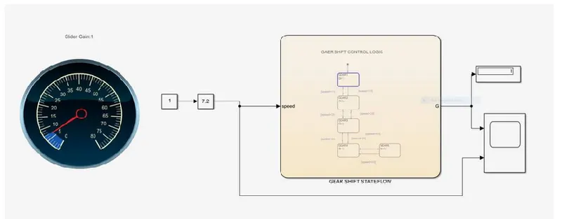
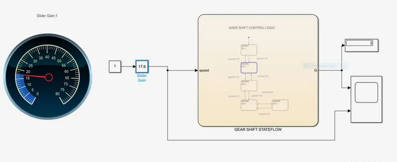
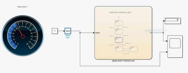
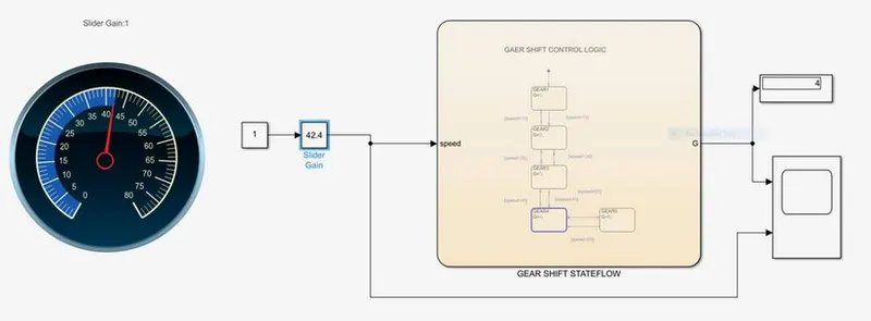
As we increse the Gear speed is also Incresed as per the given data
STATEFLOW:Gear shift control logic
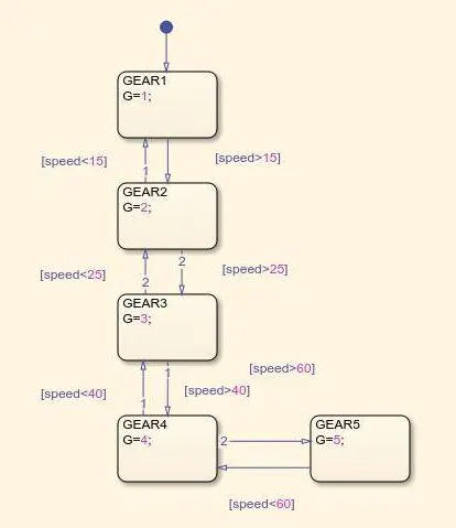
At 1st gear
At 2nd Gear
At 3rd Gear
At 4th Gear
At 5th gear
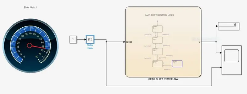
Output
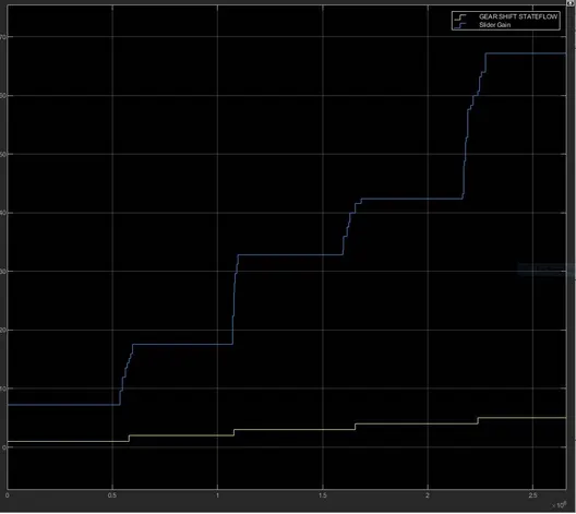
From output we can see that the shifting occurs according to the input.